Publisher’s version / Version de l'éditeur:
The Indian Concrete Journal, 78, November 11, pp. 51-57, 2004-11-01
READ THESE TERMS AND CONDITIONS CAREFULLY BEFORE USING THIS WEBSITE. https://nrc-publications.canada.ca/eng/copyright
Vous avez des questions? Nous pouvons vous aider. Pour communiquer directement avec un auteur, consultez la première page de la revue dans laquelle son article a été publié afin de trouver ses coordonnées. Si vous n’arrivez pas à les repérer, communiquez avec nous à PublicationsArchive-ArchivesPublications@nrc-cnrc.gc.ca.
Questions? Contact the NRC Publications Archive team at
PublicationsArchive-ArchivesPublications@nrc-cnrc.gc.ca. If you wish to email the authors directly, please see the first page of the publication for their contact information.
NRC Publications Archive
Archives des publications du CNRC
This publication could be one of several versions: author’s original, accepted manuscript or the publisher’s version. / La version de cette publication peut être l’une des suivantes : la version prépublication de l’auteur, la version acceptée du manuscrit ou la version de l’éditeur.
Access and use of this website and the material on it are subject to the Terms and Conditions set forth at
Reinforcing steel corrosion in high-volume fly ash concrete
Qian, S. Y.; Qu, D.; Gu, P.; Bouzoubaâ, N.
https://publications-cnrc.canada.ca/fra/droits
L’accès à ce site Web et l’utilisation de son contenu sont assujettis aux conditions présentées dans le site LISEZ CES CONDITIONS ATTENTIVEMENT AVANT D’UTILISER CE SITE WEB.
NRC Publications Record / Notice d'Archives des publications de CNRC:
https://nrc-publications.canada.ca/eng/view/object/?id=3adf9006-b453-4312-9645-7560a3bf496f https://publications-cnrc.canada.ca/fra/voir/objet/?id=3adf9006-b453-4312-9645-7560a3bf496f
http://www.nrc-cnrc.gc.ca/irc
Re inforc ing st e e l c orrosion in high-volum e fly a sh c onc re t e
N R C C - 4 8 1 7 1
Q i a n , S . Y . ; Q u , D . ; G u , G . ; B o u z o u b a â , N .
N o v e m b e r 2 0 0 4
A version of this document is published in / Une version de ce document se trouve dans:
The Indian Concrete Journal, 78, (11), November, pp. 51-57, November 01,
2004
The material in this document is covered by the provisions of the Copyright Act, by Canadian laws, policies, regulations and international agreements. Such provisions serve to identify the information source and, in specific instances, to prohibit reproduction of materials without written permission. For more information visit http://laws.justice.gc.ca/en/showtdm/cs/C-42
Les renseignements dans ce document sont protégés par la Loi sur le droit d'auteur, par les lois, les politiques et les règlements du Canada et des accords internationaux. Ces dispositions permettent d'identifier la source de l'information et, dans certains cas, d'interdire la copie de documents sans permission écrite. Pour obtenir de plus amples renseignements : http://lois.justice.gc.ca/fr/showtdm/cs/C-42
Reinforcing steel corroSion in
high-volume fly ash concrete
The corrosion of reinforcing steel in high-volume fly ash
(HVFA) concrete slabs was investigated. Chloride ions were
introduced into the reinforced concrete slab specimens through
a natural diffusion and migration process, that is, immersion
in a ponding solution of
3.4percent sodium chloride (NaClJ.
Two HVFA concretes specimens with ASTM Class
Cand Class
F fly ash were made with a water-to-cementitious materials
ratio (w!cm) of0.32; besides, three control concretes specimens
with a w/c ofO.32, 0,43 and 0.55 were also investigated. The
concrete cover depths to the steel reinforcing bars rangedfrom
13 mm to 76 mm. The corrosion of the reinforcing steel bars
was evaluated by means of half-cell potential, tinear
polarisation and AC impedance techniques. The results
indicated that the concrete incorporating Class
Cfly ash
showed the best performance with respect to chloride-induced
reinforcing steel corrosion, followed by the control COncrete
with the wlc of0.32 and concrete containing Class
Ffly ash;
the control concretes with w/c of 0.43 and 0.55 showed the
poorest performance.
Corrosion of rebars in reinforced concrete (RC) structures is recognised as a major problem in the maintenance of the structural integrity. The most important causes for initiation of corrosion of reinforcing steel are the ingress of chloride ions and carbon dioxide to the steel surface. Chloride ion causeslocal destruction of the passive film leading to localised corrosion. Carbon dioxide, on the other hand, reacts with the hydrated cement matrix,leading to a decrease in pH and subsequent loss of steel passivity and to corrosion initiation. The need to extend concrete durability has led to the use of several admixtures· and modifications to the concrete composition. Addition of fly ash as an additive to concrete has become common practice in recent years!. The fly ash particles react with calcium hydroxide, producing
November 2004
*
The Indian Concrete Joumalcementitious products that strongly decrease concrete porosity2-l. This effect leads to an increase of the concrete resistivity and consequently to a decrease of the diffusivity coefficients of some elements, such as oxygen and chloride through the concrete5-7.Ithas been reported that a reduction of chloride diffusivity in immersed concrete to half its value was observed in concrete incorporating 50 percent of fly ash, Consequently, the corrosion process in the presence of chlorides was delayed. This behaviour was revealed in previous work on fly ash concrete immersed in sodium chloride soIutionss-lO.The use of 30 percent fly ash as partial
substitution of cement has led to a significant increase of induction time and to a reduction of the corrosion rate by one order of magnitudelO
•
In this paper, experimental investigations on the corrosion of reinforcing steel bars embeddedinslabs containing high volume fly ash (HVFA) concrete were undertaken. The corrosion resistance of the rebars in slabs was then compared to a control mix of conventional portland concrete (PC) haVing the same w / em ratio. Reinforcing steel bars were embedded in these slabs with different depths of concrete cover in order to investigate steel corrosion induced by chlorides. The chloride profile was assessed using acid soluble chloride analysis technique to examine the effect ofHVFAin reducing the ingress of chlorides into concrete. Tests of reinforcing steel bars embedded in PC with higher water / cement ratios (w / c :::: 0.43 and 0.55) were also included for comparison purpose.
Experimental programme
Concrete specimens
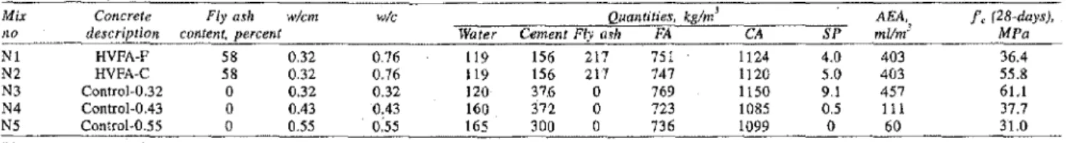
Air-entrained concrete specimens with and without high volumes of fly ash were made, Samples included two HVFA concrete mixtures made with 58 percent Class F (Nl) and Class C(N2)fly ash with a w /cm of0.32,and three concrete
Table 1: Mixture proportions and compressive strength of the concrete
Mix Concrete Fly ash w/cm w/c
Ito description content, percent
NI HVFA-F 58 0.32 0.76 N2 HVFA-C 58 0.32 0.76 N3 ControJ-0.32 0 0.32 0.32 N4 ControJ-0,43 a 0.43 0,43 N5 Control-0.55 0 055 0:55 Water 119 119 120 160 165 Quantilies, kglm' CemenlFlya"h FA
156 217 75 I 156 217 747 37.6 a 769 372 0 723 300 a 736 AEA, t,(28-days), CA SP mllmJ MPa 1124 4.0 403 36.4 1120 5.0 403 55.8 lISa 9.1 457 6L1 1085 0.5 111 37.7 1099 0 60 31.0
FA - Fine aggregate, CA - Coarse aggregate, SP - Superplasticiser, ABA - Air-entraining agent, Control-O.32 denotes control concrete with a wlc ratlo of 0.32
Table 2: Guidelines for half-cell potential data interpretation
mixtures of conventional portland concrete with
wi
c=0.32, 0.43 and 0.55 (N3, N4, and N5, respectively). A multi-component, synthetic-resin, air-entraining admixture (AEA) was used in all the concrete mixtures. The compositions of the concrete Inixtures are listedin Table 1. 'The geometrical configuration of the concrete slab was 833 x 600 x 153 mm as shown inFig1.The embedded reinforcing bars were 15 mm in diameter black steel, 470 mm in length and an exposed surface of 2.21 x 104 mm2 achieved by coating the two ends of the reinforcement bars with epoxy (the extra surface area'of the ribs on the reinforcement was not counted). Four pairs of reinforcing steel bars were embedded in each slab with concrete covers of 13, 25, 51 and 76 mm, Fig1.'The slabs were fabricated in April 1997 and cured under wet burlap for seven days followed by exposure to air inNセィ・ laboratory for 28 days. 'They were then ponded with a 3.4 percent NaCl solution for 5.3years (duration of the experiment). 'The properties of the 」ッョセイ・エ・ slabs have been reported elsewherell
,12.
Corrosion testing techniques
There are severalョッョセ、・ウエイオ」エゥカ・ techniques available for the investigation of corrosion in reinforced concrete. In order to get a reliable assessment of the corrosion of reinforcing steel, three corrosion evaluation techniques were used in this study. They were half-cell potential, linear polarisation and AC impedance methods. E versus CuiCuSO4 (ASTMC876), mV >-200 -200 > E> -350 < セSUP > -128 -128 >E> -278 < -278 90 percent probability of no corrosion Corrosion is uncertain 90 percent probability of corrosion
Half-cell potential method
The half-cell potential method has been widely used because oUts simplicity and cost effectiveness13
,14.This method allows
the evaluation of the probability of corrosion activity through the measurement of the potential difference between a standard portable reference electrode and the reinforcing steel. The data analysis gUidelines described in ASTM C876-99 provide general principles for the evaluation of the probability of corrosion of reinforcing steel in cOncrete
structures. .
A saturated HgIHg2Cl2 electrode (SCE) was used to
measure the potential of the reinforcing steel, because the ponded water on top of the concrete samples contained chloride ions. The guideline of half-cell potential specified in ASTMC876is versusCuiCuS04electrode(CSE). 'The standard potential of saturatedCuiCuS04and HgIHg2Cl2is 318 mV
and 246 mV versus that of the standard hydrogen electrode (SHE), respectively. The difference between these two reference electrodes is 72 mY. The guidelines described in ASTM C876 provide general principles for the evaluation of the reinforcing steel corrosion in concrete. The guidelines and their .conversion values (versus SCE) are listed inTable 2, Linear polarisation method
The linear polarisation technique was used to determine the polarisation resistance and the corrosion rate of reinforcing steel bars embedded in concrete. 'The potential of the steel electrode was scanned at a slow rate of 0.1 to 0.05 mV
Is.
The tests were initiated at 20 mV below the corrosion potential,Ewrr , and terminated at 20 mV above it, while recording the
polarisation current (1). 'These tests were conducted with one of the following potentiostats,EG&G 273 or 6310, Gamry CMSI00, and Solartron 1286 or 1287. The polarisation resistance,Rp ,of the reinforcing steel is defined as the slope of
a potential-current density plot at the corrosion potential,
E,"" , as follows:
Considering the correction of potential drop due to concrete resistance(IRdrop correction), Rp'is:
where,
h.V and M. :::: the applied potential and current response, respectively,
.•.(1)
...(2)
Fig 1 A schematic plot showing the portions of reinforcIng steel bars in test slabs
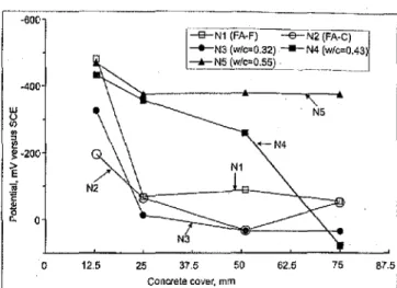
The corrosion current density is calculated from the Stern-Geary equationl5; B7.5 75 62.5 50 37.5 concrete cover. mm 25 12.5 o -400 -BOO
Fig 2 Half-cell potential measur.ements of reinforcing steel bars embedded in concrete slabs after 5.3 years of ponding with 3.4 percent NaCI solution
the so-called "Stern-Geary constant" that can be determined from theb.andb"
:; the Tafel slopes for the. anodic and cathodic reactions, respectively. where, B B I,clt
R
p ...(3) and B b.b, 2.303(b. +b.) ...(4)R, :; the concrete resistance between the reference electrode and the surface of reinforcing bar, which can be obtained by AC impedance technique.
A value of 26 mV and 52 mVis often used in the calculation for the bare steel in the active and passive stages, respectively16. For simplicity, a value of 26 mV was used to calculate all the corrosion rates in this paper since the corrosion ctirrent is inversely proportional to Rp •The criteria for
estimating the reinforcing steel corrosion are listed in
Table 317•
AC impedance method
The measurement of AC impedance spectroscopy provides information on the electrical resistivity and the dielectrical properties of the concrete cover, the corrosion rate and the mechanism of reaction on the steel!concrete interface. This technique is frequently used in the laboratory to study the corrosion of steel in concrete. Experimental investigations have shown a close relationship between the corrosion rate determined by weight loss and the values cakulated from AC impedance measurements1B,19.
w / c ratios and HVFA concrete.Fig 2 shows the half-cell potential (average of two steel reinforcing bars with same depth of concrete cover) change with increase of the concrete cover depth measured after 5.3 years ponding with 3.4 percent NaCI solution. The results indicated that the reinforcing steel bars exhibited high corrosion rates in slab N5 (control concrete with w / c of 0.55) regardless of the concrete cover depth. In slab N4 (control concrete with w/c of 0.43) the reinforcing steel bars with concrete cover depths of 13 mm and 25 mm also displayed high corrosion ratesi the only exception was those bars with 75 mm concrete cover. In all other slabs, the reinforcing bars were not corroded when the concrete cover depth was more than 25 mm, however the half-cell potential readings indicated corrosion of all reinforcing steel bars with a 13 mm concrete cover depth, except for slab N2. As expected concrete covers (>13 mm) can significantly delay the ingress of chlorides into the concrete/steel interface region.
Table 3: Criteria for estimating reinforcement corrosion conditions
Results
and discussion
Half-cell potential of reinforcing steel
Half-cell potentials were measured on the reinforcing steel· bars embedded in the conventional concrete with different
The AC impedance measurements were performed by a solartron SI 1287 Electrochemical Interface coupled with SI 1260 HF Frequency Response Analyzer (FRA) and controlled by a PC computer with Zplot and Corr-ware software. A small sinusoidal voltage signal of 5 mV was applied over the range of frequencies 100 kHz to 0.0005 Hz. The experimental results were fitted by Zview software based on the equivalent circuit after which the polarisation resistance and the corrosion rate were calculated.
200 2003 i-9-N1(FA·F) .! i,--N3 (WIC=.0.32)1 1 ' -Ie- N5 (wlc=0.55) --e-N2 (FA-C) : - - N4(w/c=O.43ll 2002 2001 2000 TIme, year 1995 1998 1S97 -700 セ .sOD (Jl
.,
:;I I!! !'>! セ rij -300 t': N3i
2 ·100The half-cell potential readings for the 13 mm concrete cover depth, varied widely from slab to slab,Fig 3, which
Fig 3 Half-cell potential measurements of reinforcing steel bars embedded In concrete slabs with 13 mm concrete cover
Extent oj corrosion
P : passive condition L: low to moderate corrosion M : moderate to high corrosion H: high corrosion
1"",,<0.1 0.1 <1"",<0.5 0.5 <1",,,< 1.0 1"",>1.0
Corrosion rate. pAlcm2
Table 4: Probability of reinforcing steel corrosion evaluated for different concrete mixes and differing concrete cover depths from half. cell potential measurements
Slab Concrete Concrete cover depth, nun
no description 13 13 25 25 51 51 76 76 N2 HYFA-C H L L L L L L L N3 Control-O.32 H U L L L L L L NI HVFA-F H H U L L L L L N4 Control-O.43 H H H H H U L L N5 Control·D.55 H H H H H H H H
Note;L: 90 percent probability of no corrosion; U: Uncertain state of cOITosion; H: 90 percent probability of corrosion
made it possible to compare the performance of different types of concretes. The potentials for concrete slabs Nl, N4 and N5 shifted into the most negative range in 2002, while N2 (HVFA Class C fly ash) maintained the most positive values followed by slab N3.
Table 4 lists the detailed probability of corrosion for all
reinforcing steel bars embedded in the concrete slabs (including control concrete slabs with different
wi
c ratios) with different thicknesses of concrete covers evaiuated after 5.3 years of ponding in 3.4 percent NaCI solution by half-cell potential technique according to the ASTM C876.Itclearly shows that the concrete slabN2, that is, the concrete slab with HVFA Class C fly ash had the best performance, followed by slab N3 (control concretewi
c=0.32) and slab Nl with HVFA Class F fly ash. The concrete slabs N4 and NS (control concrete with wIe
ratio of 0.43 arid 0.55, respectively) had the poorest performance.Corrosion current measurements by linear polarisation
Fig 4 shows the corrosion current density obtained by the linear polarisation technique. The corrosion current densities .(average of two steel reinforcing bars) are plotted versus increasing cover depth for the concrete slabs containing high volume fly ash and the control slab (w/c= 0.32). When the thickness of concrete cover is 25 mm or higher, the corrosion current densities of reinforcing steel bars were all lower than 0.1
!LA
I
cm2indicating that they were still in the passive condition. However, the difference in the corrosion current densities on the reinforcing steel bars with 13 mm concreteTable 5: Corrosion state of reinforcing steel evaluated for different concrete mixes and differing concrete cover depths from linear polarisation
Slab Concrete . Concrete cover depth. mm
flO description 13 13 25 25 51 51 76 76 N2 HVFA·C L P P P P P P P N3 Control·O.32 L L P P P P P P Nl HVFA·F L M P P P P P P N4 Control-O.43 H H H H H H P P N5 Control-O.55 H H H H H H H H
Note:p, Passive; L: Low; M: Moderate; H: High
cover were quite significant.It is clearly shown that the concrete slab N2 (Class C fly ash) had the best performance, followed by slabs N3 (control w
Ic
=0.32) and Nl (Class F fly ash). The results from slabs N4 and N5 are not shown in Figs 4 and 5 since their current densities on most reinforcing bars were very high, Table 5.Fig5 illustrates the changes in corrosion current densities with time on the reinforcing steel bars with a 13 mm concrete cover. These measurements were carried out for up to 5.3 years of ponding in 3,4 percent NaCl solution.Itcan be seen that the corrosion current density started to increase from 1998 and reached the highest, then reduced in 2002 for the slab N3 (control slab). In contrast, the current density for slab N2 remained the lowest.
Table 5 summarises the corrosion state of reinforcing steel
bars embedded in all the slabs evaluated by the linear polarisation method after 5.3 years of ponding in 3.4 percent NaCl solution.Itshows dearly that the concrete slab N2 had the best performance followed by slab N3 and Nl. As expected, the slabs N4 and N5 had the worst performance. Corrosion current measurements by AC
impedance
To interpret the AC impedance spectra, an equivalent circuit fitting procedure is commonly used. The complexity of the reinforced concrete (RC) system makes this approach difficult. Sometimes, different models have to be tested to obtain the best fit and also to· have physical meaning for the metal/ concrete ゥョエ・イヲ。」・セッMRRN . 1.1 1.5 N E 0.9 Ng1.2
セ
0.7 セ セセセ
<::,0.9'"
0.5 '0; c c'"
セ 0.6..,
0.3 E -a セ セ ::J 0.1 (30.3 tJ•
...
-0.1a 0 12.5 25 37.5 50 62.5 75 87.5 1997 Concrete cover, mmFig 4 Corrosion current densities obtained by linear polarisation technique on
reinforcing steel bars embedded in concrete slabs (measurements after 5.3 years of ponding with 3.4 percent NaCl solution)
54
2001 2002 2003
Fig 5 Corrosion current densities obtained by Unear polarisation technique on reinforcing steel bars embedded in concrete slabs with 13 mm concrete cover
It is generally accepted that the phYSical model of the steel/ concrete interface consists of a layer of iron oxides and hydroxides film in the passive stage and an interfacial
film
adjoined to the concrete matrix21-23. Many eqUivalent circuits have been proposed to describe the different stages of the steel/ concrete corrosion process including active, and passive corrosion pTocesses involving diffusion control, passive film formation and macro-cell corrosion etc22.24'26..The corrosion current for reinforcing steel in concrete slabs was
Rp (a) simple equivalent glrgult
Table 6: Corrosion state of reinforcing steel evaluated for different concrete mixes and concrete cover depths from AC impedance*
Slab Concrete Concrele cover depth, mm
no description 13 13 25 25 5/ 5/ 76 76 NZ HVPA·C P P P P P P P P N3 Conlrol-G.32 L L P P P P P P Nt HVFA-F L L P P P P P P N4 ControJ-GA3 H H M H L L P P N5 Control-G.55 H H H H H H H H
Nole: P: Passive; L: Lciw; M: Moderate; H: High
(b) modIfied equivalent circuit
Fig 6 Equivalent circuit used in AC impedance fitting process
obtained using the AC impedance technique. The values of
the polarisation resistance, Rp , and the concrete resistance,
Rc ' were obtained by the "best-fit" of the experimental
impedance spectra using one of the equivalent circuits shown
inFig6. Two types of equivalent circuits were used in this
work. A simple equivalent circuit (circuit· (a») was used in
most of the analyses.Inthis equivalent cirmit, a pure resistor,
represent ohmic resistance,
Rc,
isin.series with a parallelcombination of a resistor (polarisation resistance,Rp) and a
frequency dependent double layer capacitor,Cdl •The latter,
also called a constant phase element (CPE) is introduced to
account for a depressed semicircle on complex ploe7,28.A
modified equivalent circuit (circuit(b))was also used in this
study. This equivalent circuit consisted of a resistor,1\:, in series with tWo parallel combinations of a resistor and a CPE,
Riwith CjandRpwithCdl •These RC parameters are defined
as follows:
steel bars embedded in the concrete slab N2 is shown inFig7.
The fitted value of Rprepresents the overall condition of the
steel surface corrosion and does not identify the passive or active corrosion areas even thou?h the latter has the major
contribution to the measured Rp2 •The value of Rpwas used
to calculate the corrosion rate based on the Stern-Geary relation (equation 3) and a "B" value of 26 mV was applied.
The value of
Rc
Was used to correct theiRdrop in the linearpolarisation measurement.
The relation of corrosion current density of reinforcing steel bars versusconcrete cover (after 5.3 years ponding with
chloride solution} are plottedin Fig8. The reinforcing steel
bars with a 25inrri.concrete cover or thickerinall slabs had a
very small corrosion current density « OJpAlcm2) ,Higher
corrosion current densities were observed for most concrete slabs with 13 mm concrete cover except the concrete slab N2 in which the current density remained very low. The results for slabs N4 and N5 were hot shown in this figure since their
values were too larger for this figure, Table 6.
• Rc :the concrete resistance
• R, and Cr:steel!concrete interface film resistance and
capacitance
• Rpand Cdl :steel polarisation resistance and
double-layer capacitance.
The complex-plane plot of AC Unpedance measurement data (symbols) and fitting results (solid line) for reinforcing
The corrosion rates evaluated by the AC impedance
method were also analysed using the criteria listedin Table 2,
as shown inTable 6. It is clearly seen that the slab N2 with
Class C fly ash had the best performance followed by the
slabs Nt (Class Fflyash) and N3 (the control concrete
wi
c=
0.32). The difference in the current density betwee11: slabs Nt and N3 was very small. The worst performances were those
of slabs N4 andN5.
·8000
Slab concrete Rakingbydifferent no description techniques Half-cell LP AC N2 HVFA-C N3 Control-G.32 2 2 2 NI HVFA-F 3 3 2 N4 Control-O.43 4 4 4 N5 Control-O.55 5 5 5
Table 7: Overall performance ranking with regard to corrosion of reinforcing steel bars in concrete slabs
ッャMMMMN[ZZセ ....Mセ⦅Mセ⦅セ⦅
o 12,5 25 37.5 50 62.5 75 87.5 Concretecovet, mm .
Fig 8 Corrosion current densities obtained by AC impedance technique on reinforcing steel bars embedded In concrete slabs (measurement after 5.3 years ponding with 3.4 percent NaCI solution)
12000
4000 . 6000
Z'
Fig 7Acomplex-plane plot of AC impedance for reinforcing steel bars embedded In concrete slab N2; the symbols represent the experimental data and the line the fitted results
0.3
N-4000
o
0Overall performance ranking of concrete slabs The performance of the different concrete slabs tested using the half-cell potential and linear polarisation AC impedance
techniques are listed in theTable7. It can be seen that they are
in very good agreement. The slab N2 (HVFA Class C fly ash) had the best performance followed by the control slab N3 (control concrete w
Ic
=0.32) and slab Nl with respect to the reinforcing steel corrosion. The slabs N4 and N5 (control concretes withwi
c =0.43 and 0.55, respectively) had the worst performance.Conclusion
General
HVFA concretes (w/cm = 0.32) and control concrete (w
I
c = 0.32) performed excellently in the corrosion testreported. The reinforcing steel bars with a cover of 25 mm or
greater wereina passive state after5.3years of exposure in
3.4 percentNaClウッャオエゥッョウセ As most specifications for structural
concrete exposed to aggressive media specify a minimum
cover of37 mm, the test results obtained indicate no likelihood
of corrosion of reinforcing steel inHVFA concrete with w/cm of0.32during the service life of concrete structure.
The data reported in this investigation together with chloride-ion profiles in concrete slabs can be used to develop prediction model for service life of concrete structures
セクーッウ・、 to chloride-ions.
Specific
The corrosion of reinforcing steel bars embedded in the concrete slabs containing high volumeflyash was investigated by half-cell potential, linear polarisation and AC impedance techniques, The performance of these concrete· slabs and concrete cover depths in delaying corrosion of reinforcing steel bars was evaluated after 5.3 years of ponding with a 3.4 percent NaCl solution. Their performance was compared to conventional portland cement concrete and concrete slabs with high
wi
c. The results obtained by these different techniques wereinvery good agreement.The concrete slab N2 (containing high volumes of Class C fly ash) had the best performance. The corrosion of the reinforcing steel bars was initiated only on the steel bars with 13 rom concrete cover and the corrosion rate was lower than that obtained in the control slab N3(",/c
=
0.32).The control slab N3 (control concrete, w
Ie
=
0.32) and slab Nl (containing high volumes of Class F fly ash) also had a good performance. The corrosion of the reinforcing steel bars with a 13 mm concrete cover depth was in the moderate to high corrosion state, but the reinforcing steel bars with thicker concrete covers were still in the passive condition, according to the measured corrosion rates.The corrosion of reinforcing steel bars embedded in portland cement concretes with high water/cement ratios (w
I
c=
0.43 and 0.55) was significant. Substantial corrosion of the reinforcing steel bars was found in slab N4(wi
c=
0.43)56
with a 50 mm cover and in slab N5 (w
I
c=0.55), even with a 7S mm concrete cover.AcknOWledgement
Grateful acknowledgement is made to the Canada Centre for Mineral and Energy Thchnology (CANMET) of Natural Resources Canada for the financial support to this project. References
1. SHADLE, R. The benefits of utilizingfly ash in producing self-consolidating
concrete(SCC), http://www.masterbuilders.com/eprise/ inain/MBT/ Content/Products/Rheodynamic / ACBNfpapers/FlyAsinSCC.pdf.
2. FRAAY, A.L.A. BIJEN,J.M.,andDEHAAN,YM.The reaction of the ash in concrete:
A critical examination,Cement and Concrete Research,March 1989, Vol.2,
No. 19, pp. 235-246. .
3. _ _Use offly ash in concrete,ACI Committee Report 226,ACI Materials Journal,1987, p. 381.
4. THQMASMDA. and MATTHEWS, J.D. The permeability of fly ash concrete,
Materials and Structures,1992, Vol. 25,p.388-396.
5. LIN,SH. Chloride diffusion in a porous concrete slab,Corrosion,December
1990, Vol. 46, p. 964-967.
6. MANGAT, ES. and GURUSAMY,K. Chloride diffusion in hbre reinforced concrete
containing PFA,Cement and Concrete Research,July 1987, Vol. 17, No.4,
pp.640-650.
7. SALTA, M.M.Corrosion and Corrosion Protection of Steel in Concrete,(Editor:
Swamy, RN.) SheffieldAcademk Press, Sheffield, UK, 1994. p. 794-805. 8. MONTEMOR, M.F., SIMOES, A.M.P., SALTA, M.M. and FERREIRA, M.G.S. The
assessment of the electrochemical behaviour of fly ash-containing concrete
by impedance spectroscopy,Corrosion Science,1993, Vol. 35, p.1571-1578.
9. :MoNTEMOR, M.F., SIMOES, AM.P., SALTA,M.M. and FERRElRA,M.G.S. Corrosion
and Corrosion Protectionッヲsエ・セQ in Concrete,(Editor: Swamy, R.N.) Sheffield,
UK, 1994. p. 751-761. .
10. MoNTIJMOR, M.F.,SIMOES, A.M.P. and SALTA, M.M. Effectofflyashonconcrete
reinforcement corrosion studied by EIS,Cement and Concrete Composites,June
2000, Vol. 22, No.3, pp. 175-185.
11. Cu, P., BEAUDOIN, J.J. and BALIXXK, B. Corrosionresistance ofreinforcing steel
in cementitious concrete exposed to chloride solution,NACE Northern Area
Eastern Conference and Exhibiton,October 24 - 27, 1999, paper 9R.l.
12. Gu, P., BEAUDOIN, J.J.,ZHANG,MH. and MALHOTRA, V.M. Performance of steel
reinforcementin portland cement and high-volume fly ash concretes exposed
to chloride solution,ACIMaterials Journal,September-October 1999, Vol. 96,
No.5, pp. 551·558.
13. SrRATFULL, R.F. Half-cell potentials and the corrosion of steel in concrete,
Highway Research Record,Washington, 1973, pp. 1·433.
14. BROOMPIELD,J.,DAVIES, K., and HLADKY,K. The use of permanent corrosion
monitoring in new and existing reinforced concrete structures,Cement and
Concrete Composites,February 2002, Vol. 24, No.1, pp. 27-34.
15. _ _EG and G Princeton Applied Research Application Note -140 Linear polarization and Note -148 "Tafel Plot".
16. ANDRADE,C.and GONZALES, J.A. Quantitative measurements of corrosion
rate of reinforcing steels embedded in concrete using polarization resistance
measurements,Werkstoffe und Korrosion,1978, Vol. 29, No.8, pp. 515-519.
17. FEUU, 5., GONZALEZ,JA. and ANORA DE,C. Electrochemical methods for
on-site determinations of corr'osion rates of rebars,Techniques to Assess the
Corrosion Activity of Steel Reinforced Concrete Structures,ASlM STP 1276,
(Editors: Neal S. Berke, Edward Escalante, CharlesK,Nmai, and David
Whiting), American Society for Testing and Materials, 1996.
18. ELSENER, B. and BOHNl, H. Corrosion of steel in mortar studied by impedance
measurements,Materials Science Forum,1986, Vol. 8, pp.363-372.
19. ELSENER, B. and BOHNI, H. Monitoring corrosion of steel in,.concrete - An
impedance approach, Proceedings, European Congress of Corrosion, QYセRQ
November 1985, Vol.l, pp.1.l-1.6.
Dr Deyu Qu was an NSERC post-doctoral fellow at the Institute for Research in Construction, National Research Council Canada. Currently, he is a post-doctoral fellow in physical chemistry laboratory, Division of Chemistry, Hokkaido University, Sapporo, Japan.
•••
Dr. Shiyuan Qian is a senior research officer at the Institute for Research in Construction, National Research Council Canada. He received his Ph.D. degree in Electrochemistry. He is a member of the American Concrete Institute, Electrochemical Society, National Association of Corrosion Engineers and a member of ACI Committee on Corrosion of Metals in Concrete.
Dr (Gordon) Ping Gu is a research scientist at CANMET, Materials Technologies Laboratory, Natural Resources of Canada. Earlier, he was a research officer in the Building Envelop and Structures of the Institute for Research in Construction, National Research Council of Canada. His areas of expertise include alternative reinforcing materials for concrete structures, multi-functional corrosion inhibiting admixtures and reinforced concrete structures and pipes corrosion assessment and protection.
Mr Nabil Bouzoubaii. is a research scientist at the International Centre for Sustainable Development of Cement and Concrete (ICON), CANMET. He is a member of ACI Committees 225, Hydraulic Cements, and555,Concrete with Recycled Materials. His research interests include blended cements, sel£-consolidating concrete, and concrete durability.
26. ANDRADE,c.,MARlDONA,1.R.,FELlU,5.,GONZALES,J.A. and FELlU, JR,S.The effect of macrocells between active and passive areas of steel reinforcements, Corrosioll Science, 1992, Vol. 33, No.2, pp. 237-249.
24. AWNSO, M.C. and ANDRADE, C. Corrosion of steel reinforcement in carbonated mortar containing chloride,Advances in Cement Research, ]988, Vol. 1,pp.
155-163.
25. ANDRADE,c.,MERlNO,P.,NOVOA,X.R.,PEREZ,M.e.and SOLER,1.Passivation of reinforcing steelinconcrete,Materials Science Forum, 1995,Vols.192-194, pp.891-898.
23. JOHN, D.G., SEARSON,r.e.and DAWSON, J.L. UseofAC impedance technique in studies on steel in concrete in immersed conditions,British Corrosion Journal, 1981, Vol. 16, No.2, pp. 102-106.
20. HACHANl;L., CARPIO, J., FlAUD, C., RAHARlNAlVD, A. and 'TRrK1, E. Steel corrosion in concrete deteriorated by chlorides and sulphates: ElectrochemicalslUdy using impedance spectrometry and stepping downセ current method,Cement and Concrete Research, 1992, Vol. 22., No.1, pp. 56-66.•
28. COLE,K.Sand COLE,RH.Dispersion and absorptionindielectrics1.Alternating current characteristics,Journal of Chern. Phys., 1941,9, pp. 34]-351. 27. SWYTERS-REHBACH, M. ·and SLUYTERS,JH. Electroanalytical Chemistry, Vol. 4,
(Editors:A.J.Bard,Marc€1 Dekker), New York, ]970, pp.l-]25.
22.LEMOINE;1.,WENGER,F. and GALLAND, J. Studyofthe corrosion of concrete reinforcementbyelectrochemical impedance measurement,Corrosion Rates of Steelin Concrete, ASTM STP 1065. (Editors: NS.Berke, V. Chaker and D. Whiting),1990,American Society for Testing and Materials, pp 118-]33. 21. CRENTSlL,K.KS.,GLASSER,P.P.and IRVINE,J.T.S. Electrochemical characteristics
of reinforced.concrete corrosion as determined by impedance spectroscopy, British Corrosion Journal, 1992, Vol. 27, No.2, pp. 113-118.
29. Gu,P.,ELUOIT,5.,HRISTOVA, R., BEAUOOIN, J.J., BROUSSEAU, R., and BALDOCK, B. A study ofcorrosion inhibitor performanceinchloride contaminated concrete
byelectrochemical impedance spectroscopy,ACEMaterials Journal, 1997, Vol. 94, No.5, pp. 385-395.