CAVITATION METHODS IN THERAPEUTIC ULTRASOUND: TECHNIQUES, MECHANISMS, AND SYSTEM DESIGN
by
Shunmugavelu D. Sokka
Bachelor of Science in Engineering, Biomedical Engineering, Electrical Engineering & Biology
Duke University, 1996
Masters of Science, Electrical Engineering and Computer Science
Massachusetts Institute of Technology, 1999
SUBMITTED TO THE HARVARD-MIT DIVISION OF HEALTH SCIENCES AND
TECHNOLOGY IN PARTIAL FULFILLMENT OF THE REQUIREMENTS FOR THE
DEGREE OF
DOCTOR OF PHILOSOPHY IN ELECTRICAL & MEDICAL ENGINEERING
AT THE
MASSACHUSETTS INSTITUTE OF TECHNOLOGY
DECEMBER 2003
C 2003 Shunmugavelu D. Sokka. All rights reserved.
The author hereby grants to MIT permission to reproduce and distribute publicly paper and
electronic copies of this thesis document in whole or in part.
Signature of Author
Harvard-MIT Division of Health Sciences and Technology
December 12, 2003Certified by
Kullervo Hynynen, Ph.D.
Professor of Radiology, Brigham & Women's Hospital, Harvard Medical School
A,1/
XThesis Advisor
Certified by
.
_
H. Frederick Bowman, Ph.D.
Senior Academic Administrator of HST, M.I.T & Lecturer of Radiation Oncology, HMS
Thesis Committee Chair
Accepted by
vASSACHUSETTS INS~rr -,TI
~ ~
~ ~ ~ ~ ~ ~ ~ i i i
li.Jrty tq
r
nai.
MASSACHUSETTS INSTITf'E, OF TECHNOLOGY AUG 1 9 204vlolU Ull laly, r.l.
iward Hood Taplin Professor of Medical & Electrical Engineering, M.I.T.
Co-Director, Harvard-MIT Division of Health Sciences and Technology
Cavitation Methods in Therapeutic Ultrasound: Techniques,
Mechanisms, and System Design
by
Shunmugavelu Doraivelu Sokka
Submitted to the Harvard-MIT Division of Health Sciences and Technology on November 21,
2003 in partial fulfillment of the requirements for the Degree of Doctor of Philosophy in
Electrical and Medical engineering
Abstract
Focused ultrasound is currently being developed as a non-invasive thermal ablation
technique for benign and cancerous tumors in several organ systems. Although these therapies
are designed to ablate tissue purely by thermal means, cavitation, the formation and collapse of
gas bubbles, can occur. These bubbles can be unpredictable in their timing and location and often
interfere with thermal therapies. Therefore, focused ultrasound techniques have tried to avoid
bubbles and their effects. However, gas bubbles in vivo have some potential useful features for
therapy. They greatly enhance local ultrasound absorption, and can on their own induce
mechanical damage to the tissue. In addition, bubble clouds can block ultrasound wave
propagation, providing a means to protect vital tissues during ablation of nearby pathology. If
induced and controlled properly, cavitation in focused ultrasound therapy could potentially be
very beneficial.
The first aim of this research is to design and test in vivo ultrasound exposures that
induce cavitation at appropriate times and take advantage of their absorption enhancing
properties. In addition, methods to monitor and control cavitation induction and the associated
therapy will be investigated. Second, a theoretical bubble model and acoustic field simulations
will be used to design optimal pressure fields which very tightly control the cavitation location.
These models will also be used to investigate methods for reducing the acoustic powers needed
to induce cavitation while preventing off focus cavitation. For the final phase of the research a
multi-channel, multi-frequency ultrasound amplifier system capable of delivering optimal
exposures via large scale phased array systems will be developed and tested. In total, the thesis
research will justify applications for cavitation in ultrasound therapy, and develop the technology
and methodology to optimally use cavitation and monitor its effects in vivo.
Thesis Supervisor: Kullervo Hynyen, Ph.D.
ACKNOWLEDGEMENTS
I would like to thank my thesis advisor, Kullervo Hynynen, for all his support, encouragement, and patience over the years. I cannot express in words how much I have benefited from his mentorship and guidance. He is the consummate professional and was always accessible. In the later years of my thesis work, I was lucky to have almost daily illuminating discussions on not only my work but also the future of field. Kullervo is a true visionary, and I am honored to
have worked with him. I also thank the other members of my thesis committee, Roger Mark and
Fred Bowman. I am deeply grateful for their support and patience during the later phase of my
thesis work. Both have had a tremendous impact on my personal and professional development.
I thank everyone in the Brigham & Women's focused ultrasound laboratory, past and
present. They have been my greatest teachers and even better friends. I would like to thank Todd Fjield, Doug Daum, Greg Clement, and Mark Buchanan for teaching me everything I know about ultrasound. Their openness and patience with my questions was truly unparalleled. I also thank Nathan McDannold, Randy King, and Heather Martin, for their tireless efforts in the MRI animal work in this thesis. I am deeply indebted to Jose Juste who provided tremendous technical knowledge on the electronics portion of this research. And, I am also grateful to Thomas Gauthierand Eduardo Labat who helped me with ultrasound experiments during my graduate work.
Without all of these individuals, my extremely collaborative work would not have been possible.
In the lab, we had a culture of knowledge exchange through vigorous debate. I would like to thankJonathan Thierman, Jason Raymond, Subha Maruvada, Jie Sun, Jason White, Tonia Giesecke,
Elisa Konofagou, Natalia Vykhodtseva, Chrisitina Silcox ,Chris Connor,, Erich Caulfield, Lisa Treat, Peter Huber, Kagayaki Kuroda, Nickoli Sheikov, Sue Agabian, Ibrahim Hallaj, and NadineSmith for teaching me about so many things: professional, personal, and the eclectic. My years
with my labmates were truly the greatest of my life, and I hope to have enduring life-longfriendships with all of them.
All aspects of this work were supported by grants from the NIH National Cancer Institute. Support for the initial animal experiments were also received from Insightec-TxSonics. I thank
these organizations for their support. I also thank the Whitaker Foundation for funding my
graduate fellowship. Their support afforded me the freedom to find my research group and topursue the research I was passionate about. The Harvard-MIT division of Heath Sciences and Technology (HST) also provided graduate fellowship funding at critical times during this work, and I thank my department for this financial support and also for the countless academic, professional, and personal opportunities they have provided me. Specifically, I would like to
Keiko Oh, Cathy Modica, Domingo Altarejos, Ron Smith, Jennifer Weiss, and Patty Glidden in the HST student affairs office for all their support throughout the years.
Finally, I would like to thank my family: my brothers, Thanikai and Kumar, my
sister-in-law, Preetha, and my extended family, the Saravanabhavans', the Umamaheswarans', and the
Ravichandrans'. I am deeply indebted for their emotional support throughout my graduate work. I thank my father who instilled in me the drive to complete this thesis despite all the challenges; Ihope he is smiling from heaven. And, I dedicate this thesis to my guiding lights: my mother who
has made me everything I am today, and my wife, Yamini, whose love seems to make everything
possible for tomorrow.
TABLE OF CONTENTS
1 INTRODUCTION ... ... 12
1.1 BACKGROUND ... ... 12
1.2 H ISTO RY ... 14
1.3 NOTABLE RECENT TECHNOLOGICAL ADVANCES ... 15
1.4 CAVITATION ... 16
1.4.1
Theoretical Cavitation Models ... ...
17
1.4.2
Cavitation in Therapeutic Ultrasound
... 20
1.5 ULTRASOUND PHASED ARRAY SYSTEMS ... 21
1.5.1
Array Geometries ...
21
1.5.2
Phased Array Construction
...
24
1.5.3
Piezocomposites ...
24
1.5.4
Ultrasound
Driving Systems ... ...
26
1.6 SPECIFIC AIMS ... 27
1.6.1
Cavitation-Enhanced
Ultrasound Heating
...
27
1.6.2
Theoretical Determination
of Optimal Cavitation Field ... 29
1.6.3
Ultrasound Phased Array System for Improved Field Control ...
30
2
MRI-GUIDED CAVITATION-ENHANCED ULTRASOUND HEATING ... 31
2.1 INTRODUCTION ... 31
2.2 MATERIALS AND METHODS ... 31
2.2.1
Experimental Apparatus ...
...
31
2.2.3
Sonications
... ... ... 33
2.2. 4
Cavitation Detector ...
35
2.2.5
Experimental Procedure ... 35
2.2.6
MRI ...
36
2.3 RESULTS ... 37
2.3.1
Temperature versus time at the thermalfocus..
.
....
37
2.3.2
Spatial Temperature Maps ...
41
2.3.3
Lesion Size and Shape ...
46
2.4 DISCUSSION ... 50
3
CAVITATION-ENHANCED ULTRASOUND HEATING: MECHANISMS,
ACOUSTIC AND MRI MONITORING, AND CONTROL TECHNIQUES ... 55
3.1 INTRODUCTION ... 55
3.2 MATERIALS AND METHODS ... 55
3.2.1
Experimental
Apparatus ...
55
3.2.2
Cavitation Enhanced Heating Sonications
... 56
3.2.3
Cavitation Detector Signal Acquisition and Analysis
.
...
58
3.2. 4
MRI ... 61
3.3 RESULTS . . ... 61
3.3.1
Cavitation Spectra versus time ...
...
61
3.3.2
Temperature versus time at the thermalfocus... 65
3.3.3
Spatial Heating Distribution
... 68
3.3.4
Lesion Analysis ...
...
... 71
4
DESIGN OF MULTI-FREQUENCY CAVITATION FIELDS FOR SPATIAL
CONTROL OF CAVITATION ...
79
4.1 INTRODUCTION ... 79
4.2 METHODS ... 81
4.2.1
The bubble m odel... 81
4.2.2
Tested Multi-frequency waveforms ...
84
4.2.3
Experimental Verification of Theoretical Results ...
87
4.2.4
Acoustic Field and Cavitation Field Calculations ...
88
4.3 RESULTS ... 90
4.3.1
Relative Cavitation Thresholdsfor Various Families of Pressure Waveforms .... 90
4.3.2
Experimental Validation of Relative Cavitation Thresholds ...
...
94
4.3.3
Cavitation Fields Generatedfrom Multi-Frequency
Acoustic Fields ... 95
4.4 CONCLUSIONS ... 101
5
DESIGN AND EVALUATION OF BROADBAND MULTI-CHANNEL
ULTRASOUND DRIVING SYSTEM FOR LARGE SCALE THERAPEUTIC PHASED
ARRAYS ... 1045.1 INTRODUCTION ... 104
5.2 M ETH O D S . ... 104
5.2.1
Therapeutic Piezocomposite Transducer Arrays ... 104
5.2.2
Design Requirements
for Large Scale Multi-channel
Broadband Ultrasound
D riving System ... ...
105
5.2.3
The Ultrasound Driving System ...
106
5.3 R ESU TS . . . . ... 118
5.3.1
Electrical Measurements
...
118
5.3.2
Acoustic Measurements ...
120
5.4 DISCUSSION ... 128
6
CONCLUSIONS AND RECOMMENDATIONS FOR FUTURE WORK ... 129
6.1 CONCLUSIONS ... 129
6.2 RECOMMENDATIONS FOR FUTURE WORK ... 131
LIST OF FIGURES
Figure 1-1. Figure 1-2. Figure 1-3. Figure 2-1. Figure 2-2. Figure 2-3. Figure 2-4. Figure 2-5. Figure 2-6. Figure 2-7. Figure 2-8. Figure 3-1. Figure 3-2. Figure 3-3. Figure 3-4. Figure 3-5. Figure 3-6. Figure 3-7. Figure 3-8. Figure 4-1. Figure 4-2. Figure 4-3.Diagram of Sector-Vortex Array adapted from Cain and Umemura ... 23
Diagram of the combined concentric ring and sector-vortex array ... 23
Diagram of a 1-3 composite piezoelectric ... 26
Schematic of the experimental setup ... 32
Temperature profiles at the focus of the 1.1 MHz sonications ... 38
Temperature profiels at the focus of the 1.7 MHz sonications ... 40
Temperature imaging during sonication ...
42
MR T2 image of the resulting lesion ...
43
Temperature and T2-weighted imaging of fat sonication ... 45
MR T2 images of lesions at different energy levels ... 47
Thermal dose contours of lesions at different energy levels ...
48
Time profile of the 4 cavitation-enhanced heating exposures ... 57
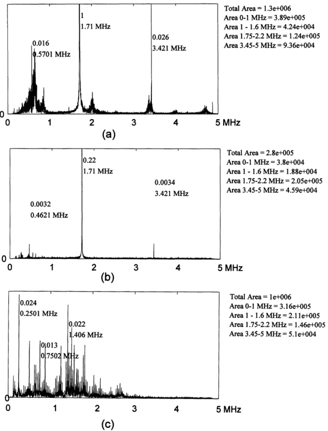
Sample Spectra of cavitation detector signal ...
60
Spectral energies of the detector signal in the 0 to 1 MHz band ... 62
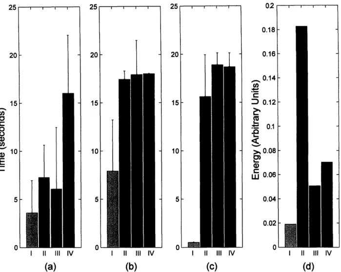
Time duration of spectral energy in different frequency bands ... 65
MRI Temperature versus time curves at the thermal focus ... 67
MRI spatial temperature maps for 5 distinct lesion types ... 69
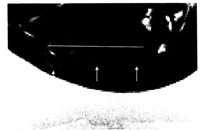
MRI imaging showing the bubble shielding effect of cavitation ... 70
MR imaging of lesions generated from 3 different sonication types ... 73
First family of curves where the zero crossing of biphasic period is varied ... 85
Second family of curves... 86
Figure 4-4. Experimental setup for measuring cavitation threshold.
...
88
Figure 4-5. Relative cavitation threshold for the first family of curves ...
91
Figure 4-6. Relative cavitation threshold for the first waveform family with 3 frequencies ... 92
Figure 4-7. Relative Cavitation Threshold for the second family of curves ... 93
Figure 4-8. Relative Cavitation Threshold for the third family of curves ... 94
Figure 4-9. Relative cavitation thresholds for dual-frequency equal amplitude excitation ... 95
Figure 4-10. Acoustic and cavitation fields of a dual-frequency ultrasound exposure ... 97
Figure 4-11. Acoustic and Cavitation fields of a triple-frequency ultrasound exposure ... 98
Figure 4-12. Acoustic and Cavitation fields of a dual-frequency equal amplitude exposure ... 100
Figure 4-13. The cavitation field along the transducer axis ... 101
Figure 5-1. Block diagram of the Ultrasound Driving System ... 107
Figure 5-2. The Digital Control State diagram ...
... 110
Figure 5-3. Circuit topology of the analog components of the amplifier system ... 111
Figure 5-4. Photograph of the 50-channel ultrasound driving system board ... 112
Figure 5-5. Theoretical maximum current and power delivered to the load ... 115
Figure 5-6. The maximum power versus frequency per channel ... 119
Figure 5-7. Electrical impedance and driving performance for the 8-element array ... 121
Figure 5-8. Acoustic field scan of phased transducers ... 123
Figure 5-9. Dual frequency continuous wave excitation ... 125
Figure 5-10. Single Pulse Generation ... 127
LIST OF TABLE
Table 2-1. Number of sonicatiobs in each control and experimental group ... 34
Table 2-2. Ratios of experimental to control lesion size with 1.7 MHz transducer ... 49
Table 2-3. Lesion width to height ratios for all sonications with 1. MHz transducer ...
50
Table 3-1. Number of Cavitation Enhanced Heating Sonications ... 58
Table 3-2. Lesion Shapes and Side Effects for the Different Sonication Types ... 71
Table 3-3. Lesion Volumes of Bubble-Enhanced Heating relative to control ... 73
Table 4-1. Constants used in the Keller-Miksis Bubble Model ... 82
Table 5-1. Amplifier Board State Descriptions ...
...
110
1
Introduction
1.1 Background
In medicine, various device-based interventional techniques have been investigated to induce
morphological tissue changes as non-invasive or minimally invasive alternatives to surgery.
Radiation therapy has probably been the most successful device-based intervention to date as it is used widely to kill proliferating cancer cells. However, side effects of radiation both to patients and practioners, and the inability to appropriately focus the radiation-induced damage limit its potential. Among the most promising alternatives to ionizing radiation-based interventions are thermal techniques. Devices for thermal therapy include ultrasound transducers, lasers, and antennas operating at microwave or RF frequencies. These techniques aim to create local bioeffects (structural or functional changes) in a target area (typically tumors or malfunctioning tissue) while leaving the surrounding healthy tissues unharmed. The induced temperature rise can be high enough (thermal ablation) to cause coagulative necrosis, protein denaturization-based cell death, orjust a few degrees for an extended period of time (hyperthermia) to sensitize the tissue for adjuvant
radiation or chemotherapy. These techniques can be highly localized, they can be applied as minimally invasive or non- invasive procedures, and they do not use harmful ionizing radiation. These properties offer obvious advantages over standard surgical, radiation, and even chemotherapy treatments and procedures.
Of all of these interventional techniques, ultrasound is unmatched in its flexibility and its
potential for use in several applications. At therapeutic frequencies, 0.5 to 4 MHz, ultrasound canbe tightly focused (on the order of the wavelength) with very little power deposition in the near
field. A typical ultrasound wave at 1.0 MHz has a wavelength of 1.5 mm and a penetration depthof roughly 10 cm (Hynynen & Lulu 1990) in soft tissue. In comparison, a microwave, which
radiates at 2450 MHz has a wavelength of 1.8 cm and a penetration depth of only 1.7 cm in tissue (Johnson 1972). Therefore ultrasound applicators can be extracorporeal devices for noninvasive treatment. However, for difficult to access tissues, ultrasound applicators can be outfitted in interstitial probes (Diederich et al. 2000;Hynynen & Davis 1993;Lafon et al. 1998), intracavitaryapplicators (Foster et al. 1993;Hutchinson & Hynynen 1996;Sokka & Hynynen 2000), or
intravascular catheters (Hynynen et al. 1997;Zimmer et al. 1995). Ultrasound propagates and interacts with tissue as a mechanical wave; therefore, bioeffects that are mechanical in nature, notjust thermal, can be induced distinguishing it from all the electromagnetic radiation techniques.
These mechanical effects produced in vivo by high intensity ultrasound can be used therapeutically.
Ultrasound with its mechanical and thermal effects, has been investigated for several medical applications by several researchers including tumor ablation (Adams et al. 1996;Chen et al. 1993;Chen et al. 1998;Chen et al. 1999b;Fry et al. 1978;Goss 1984;Prat et al. 1995;Rowland et al. 1997;Sibille et al. 1993;ter Haar et al. 1991;Vaezy et al. 2000;Yang et al. 1991;Yang et al. 1992;Yang et al. 1993), vessel occlusion (Delon-Martin et al. 1995;Hynynen et al. 1996b;Rivens et al. 1999), hemostasis (Vaezy et al. 1997;Vaezy et al. 1998), thrombolysis (Francis et al. 1992;Porter et al. 1996), drug delivery (Unger et al. 1998), gene therapy (Greenleaf et al. 1998;Huber & Pfisterer 2000;Kim et al. 1996;Lawrie et al. 2000;Madio et al. 1998;Miller et al.1999;Unger, McCreery, & Sweitzer 1997), focal opening of the blood brain barrier (Hynynen et al.
2001a;Vykhodtseva, Hynynen, & Damianou 1994), and direct mechanical damage with cavitation
(Miller et al. 2000;Prat et al. 1994b;Vykhodtseva, Hynynen, & Damianou 1994). Non-thermal mechanisms such as cavitation, acoustic streaming (Frizzell, Miller, & Nyborg 1986), radiation pressure (Dalecki et al. 1997), and cavitation microstreaming (Miller 1987), are also being investigated as potential cellular level interventions. All of these investigations show the utility of aparticular ultrasound bioeffect for a particular application, but which bioeffect occurs in tissue for a
given ultrasound exposure is still highly variable. With advances in ultrasound phased array systems (Benkeser et al. 1987;Buchanan & Hynynen 1994;Cain & Umemura 1986;Clement et al. 2000a;Curiel et al. 1999;Daum et al. 1999a;Diederich & Hynynen 1989;Do-Huu & Hartemann 1981;Ebbini et al.. 1988;Ebbini & Cain 1991a;Ebbini & Cain 1991b;Fan & Hynynen 1995;Fjield & Hynynen 1997;Frizzell et al. 1985;Hutchinson & Hynynen 1998;Hynynen et al. 1996a;Hynynen & Jolesz 1998;Ibbini & Cain 1990;McGough et al. 1994;McGough, Ebbini, & Cain 1992;Ocheltree et al. 1984;Sokka & Hynynen 2000;Umemura & Cain 1989;VanBaren et al. 1995), precise control of the type of bioeffect, mechanical, thermal or both, with precise control of the shape and distribution of the acoustic and temperature fields seems feasible. Such control, which would allowselection of the ultrasound bioeffect in space and time, should dynamically enhance the clinical
future of therapeutic ultrasound. The primary focus of this thesis is to show that this control of the
two major ultrasound bioeffects, cavitation and thermal effects, is indeed possible and advantageous.1.2 History
As early as the 1920s and 30s, investigators, encouraged by the potential of X-ray therapy of
cancers, explored ultrasound as a treatment modality even before it was considered for diagnostics
(Nakahara & Kabayashi 1934;Szent-Gorgyi 1933;Wood & Loomis 1927). The initial studies showed mixed results as some trials even demonstrated that ultrasound induced cancer growth. In1935, Gruetzmacher demonstrated that an ultrasound beam could be focused (Gruetzmacher 1935),
and in 1942, Lynn first proposed the use of focused ultrasound for therapy (Lynn et al. 1942). In
the 1940s to 1960s, the Fry brothers, Francis and William, demonstrated the concept of focused ultrasound surgery by treating patients with brain disorders (Barnard et al. 1956;Fry et al. 1950;Fry1954;Fry et al. 1955;Fry, Barnard, & Fry 1955;Fry, Brennan, & Barnard 1957). During this time,
the exact mechanisms of the ultrasound-induced bioeffect were hotly debated. In the 1960's and70's, Padmaker Lele demonstrated with numerous in vivo studies in small animals that thermal
effects resulting from ultrasound absorption (Basauri & Lele 1962;Lele 1962;Lele 1967;Lele1975;Lele & Pierce 1973) could explain most tissue damage resulting from high intensity focused
ultrasound. Although significant understanding of the focused ultrasound therapy was gainedduring these early works, many factors still limited Focused Ultrasound Surgery (FUS) from
becoming an accepted clinical therapy. Early ultrasound treatments lacked appropriate visual and thermal feedback, which made focusing the ultrasound at the desired location, monitoring thermaldose during treatment, and post treatment assessment extremely difficult. Some of these
investigations used x-ray or ultrasound guidance for aiming the ultrasound beam, and either nomonitoring of the induced temperature or tissue changes or only selective point monitoring with
invasive temperature probes (Fry 1970;Fry 1968;Fry 1971). In addition, ultrasound hardware (the
transducers and driving systems) was not advanced enough to provide adequate acoustic and temperature field control. Despite the technological shortcomings, numerous clinical studies withhigh intensity ultrasound showing the enormous promise of the technology have been performed in
various organs, including the prostate (Beerlage et al. 1999;Bihrle et al. 1994;Chapelon et al.1999;Chaussy & Thuroff 2000;Eberle et al. 1996;Ebert et al. 1995;Foster, Bihrle, Sanghvi, Fry, & Donohue 1993;Gelet et al. 1999;Gelet et al. 2000;Kiel, Wieland, & Rossler 2000;Madersbacher et al. 1998;Madersbacher et al. 2000;Mulligan et al. 1997;Nakamura et al. 1995;Nakamura et al. 1997;Sanghvi et al. 1996;Sanghvi et al. 1999;Sullivan et al. 1999;Sullivan et al. 1997;ter Haar et al. 1998;Uchida et al. 1995;Vallancien et al. 1992;van Leenders et al. 2000), liver (ter Haar, Rivens,
Moskovic, & Huddart 1998;Vallancien, Harouni, Veillon, Mombet, Prapotnich, Bisset, &
Bougaran 1992), bladder (Vallancien et al. 1996;Watkin et al. 1996), breast (Hynynen et al.2001c), testis (Madersbacher, Kratzik, Susani, Pedevilla, & Marberger 1998), kidney (ter Haar,
Rivens, Moskovic, & Huddart 1998;Vallancien, Harouni, Veillon, Mombet, Prapotnich, Bisset, &
Bougaran 1992), and eye (Coleman et al. 1985). Recently, treatments of various targets with FUS
surgery in more than 1, 000 patients in China have been reported ( 2001).
1.3
Notable Recent Technological Advances
Technologies for improving FUS have advanced on both the image guidance and the acoustic field control fronts and are now entering the clinical investigation phase. Visualization
techniques for localizing the diseased tissue and then monitoring temperatures during treatment
have evolved only recently. Several investigators have used ultrasonography for guidance (Fry et al. 1968;Madersbacher et al. 1995;Sanghvi, Foster, Bihrle, Casey, Uchida, Phillips, Syrus, Zaitsev, Marich, & Fry 1999;Sheljaskov et al. 1997), but ultrasound thermometry is complicated by multi-parameter dependence on temperature. Others have used CT for both focus localization andthermometry (Fallone, Moran, & Podgorsak 1982;Jenne et al. 1997), but ionizing radiation limits
CT's acceptability for real-time monitoring. MRI has established itself as the optimal imaging
modality as both guidance and thermometry with high spatial and temporal resolution is possible.MRI provides excellent soft tissue contrast for diseased tissue segmentation, while temperature
sensitive pulse sequences can be used to measure relative temperature changes with an accuracy of±0.5°C with time resolution of a few seconds (Chung et al. 1996;Ishihara et al. 1992;Samulski et
al. 1992). Several studies have shown the feasibility of MRI-guided ultrasound surgery in vivo
animal models (Cline et al. 1995;Hynynen et al. 1996c;McDannold et al. 1998;Parker1984;Stepanow et al. 1995), and more recent work has shown that MRI thermal dosimetry
techniques can be used to accurately predict the extent of thermal tissue damage (Chung, Jolesz, &
Hynynen 1999;Hazle et al. 2002).Therapeutic ultrasound hardware has also evolved dramatically over the past two decades,
mainly with the advent of phased array transducers. Ultrasonic phased arrays consist of multiple
ultrasonic generators, piezoelectric elements, arranged in a specific geometry. The phase and amplitude of each generator is varied by the electronic driving system to shape the acoustic field.Phased arrays allow for real-time beam steering, which means that the acoustic field can be
spatially and temporally designed uniquely for each application. With phased arrays, the ultrasound
focal point can be moved electronically making adjustment and localization of ultrasound energy
more precise and significantly simpler. For large tumor ablation, the focal region can be enlargedwith phased arrays to shorten treatment times (Cain & Umemura 1986;Daum & Hynynen 1999).
For applications where near field structures can distort the focus such as bone in transcranialtherapy or fat layers in abdominal targets, phased arrays can be used to compensate for the
absorbing and refracting media (Clement & Hynynen 2000;Sun & Hynynen 1998). And for tissues
that are moving or are near moving structures, phased arrays can be used to treat the target as it or
its surrounding structures are moving (Seip & Ebbini 1994). The higher field controllability afforded by phased arrays also allows for sidelobe reduction, minimizing the effects of secondary foci in the acoustic field (Hutchinson, Buchanan, & Hynynen 1996;Sokka & Hynynen 2000). All of these features provide a remarkable advantage over single element transducers and opens new avenues for ultrasound therapy.1.4 Cavitation
Ultrasound can cause tissue necrosis via two methods: 1) thermal energy absorption and 2) the implosion of cavitating bubbles induced by higher pressure ultrasound waves. Traditionally, the thermal mode has been used in FUS treatments as it is better characterized and controlled yielding
lesion sizes and shapes predicted by models (Carstensen et al. 1981;Damianou, Hynynen, & Fan
1995;Hill et al. 1994;Lizzi & Ostromogilsky 1987). FUS thermal ablation is performed with
constant levels of ultrasound intensity well below the cavitation threshold for durations of 1-30
seconds ensuring that the temperature at the focus reaches levels that denature protein causing tissue necrosis. In addition, therapy in the thermal regime can be carefully monitored with thermometry techniques as described earlier. However, studies show that there might be utility incombing acoustic/mechanical effects with thermal effects. In one approach, nonlinear propagation
generated by higher intensity ultrasound has been shown to enhance thermal effects as higher
frequencies generated in non- linear propagation have higher absorption rates (Carstensen, Becroft, Law, & Barber 1981;Hynynen 1991a;Swindell 1985). But, cavitation with heating shows evengreater promise as cavitating microbubbles not only generate higher harmonics but themselves
significantly enhance absorption and heating.Acoustic cavitation, defined as any observable activity involving a gas bubble(s) stimulated into motion by an exposure to an acoustic field, has also been extensively studied. There are two basic types of cavitation: stable and inertial cavitation (Duck 1998). Stable cavitation, the less violent event, refers to radial oscillations of gas bubbles without collapse; these radial oscillations
maybe nonlinear (Leighton 1994). In inertial or transient cavitation, bubbles can grow to twice
their initial bubble size and then have sufficient energy for violent collapse. A series of bioeffectscan occur as a result of this type of cavitation in vivo: shock waves may be propagated; acoustic
energy is often converted to heat yielding high microscopic temperatures (1000-20,000 °K (Apfel1982;Flynn 1982)); high fluid velocities can be generated; and free radicals might be formed (Edmonds & Sancier 1983). Inertial cavitation is a threshold phenomenon: in a specific medium, ultrasound exposures above a specific intensity give rise to cavitation. Cavitation thresholds in vivo have been studied yielding variable intensity values in different tissue and different frequencies (Hynynen 1991b;Lele 1977;Prat et al. 1994a;Sanghvi 1998).
1. 4.1 Theoretical Cavitation Models
The physical principles that govern the dynamics of gas bubbles in the presence of an
acoustic pressure field are extremely complex. Several factors are involved in bubble inception, growth, and collapse. In order to form a cavity in a liquid, sufficient tension is required to pullapart the liquid (Leighton 1994). In terms of liquid in an acoustic pressure field, negative pressures,
pressures below the ambient pressure, can put the liquid in tension. Impurities in the liquid, the
presence of dissolved gas, preexisting cavities, or crevices in the surfaces of the liquid container can essentially seed bubbles and all act to lower the tension required for bubble formation and cavitation. Once bubbles are seeded, they may dissolve, grow, collapse or oscillate in a pressurefield. Bubbles in the absence of an acoustic field generally tend to dissolve due to surface tension,
especially smaller bubbles as surface tension varies inversely with the radius of the bubble.
However, stabilizing agents, such as ions, organic molecules, and surfactants, can sufficiently lower surface tension to stabilize gas bubbles in vivo. The presence of an acoustic pressure fielddramatically alters the behavior of these bubbles. The simplest way of modeling a bubble's
behavior to an acoustic pressure field is as a driven harmonic oscillator with the gas providing the stiffness and the surrounding liquid supplying the inertia. First-order viscous damping can be included by adding a damping term, but the harmonic oscillator neglects surface tension andviscous and thermal dissipation and assumes small amplitude oscillations. The harmonic oscillator model does provide some utility as it adequately describes stable cavitation and provides the means to calculate resonance frequency for a given bubble radius. This frequency is known as the Minnaert resonance frequency. For air bubbles in water at 1 atmosphere, the resonance frequency
3 mos-'
simplifies to ~ , where Ro is the equilibrium or initial bubble radius.
Although the harmonic oscillator model predicts bubble behavior under very specific linear
situations, the bubble is essentially a nonlinear oscillator. Several researchers have modeled nonlinear bubble dynamics over the past half-century. Most models have as their basis the classical Rayleigh-Plesset equation which models a single bubble in an infinite incompressible medium and assumes that the bubble motion is spherically symmetric. The equation is shown below with R as the time-varying bubble radius, p as the density, a as the surface tension, rl as the shear viscosity, K as the polytropic index, Ro as the initial bubble radius, pv as the vapor pressure,po as the ambient pressure, and P(t) as the time-varying pressure field at the bubble.
= Po
+- Pv
+ Pv
2a
4R
Po -
P(t)
2
={(p
Ro PV1J R
2
v
2o4R
°
t}
(1-1)
The Rayleigh-Plesset equation has some serious limitations, a primary one being liquid
incompressibility; this assumption limits the model's ability to completely describe violent bubble
collapse. Many researchers have added compressibility to this model by various mechanisms (Flynn 1964;Flynn 1975a;Gilmore 1952;Keller & Miksis 1980;Kirkwood & Bethe1942;Prosperetti, Crum, & Commander 1988), and their results have been validated by experiment (Gaitan et al. 1992). These equations, despite not being very representative of bubble activity in
tissue, can be used to make predictions of cavitation inception and cavitation thresholds in vivo.
Bubble activity in tissues involves bubble clouds and various bubble stabilizing agents. These models neglect inter-bubble forces known as Bjerkenes forces that tend to attract bubbles to each other and are relevant in bubble clouds. Ionic and molecular agents that lower surface tension are also neglected. In addition, the models assume that the liquid is a Newtonian fluid, whereas tissue is generally non-Newtonian. These models are also very dependent on initial bubble radii and gas concentrations, and these parameters are not easily measurable in any local tissue environment.Despite the above limitations, these bubble models can provide general trends on cavitation
thresholds and bubble responses to various acoustic pressures. Apfel has used one of these
nonlinear models to predict cavitation thresholds in vivo, and has theoretically shown the
dependence of inertial cavitation threshold on frequency, initial bubble radii, and local gasconcentration (Apfel 1981). In later work, he and his colleagues showed theoretically that transient
bubble collapse occurs when the compressed gas temperature exceeds 5000 K (Holland & Apfel 1989). At this temperature, bubbles are to have acquired sufficient energy for violent collapse. Thegas temperature versus time can be computed from the time-varying bubble radius with some
assumptions on the nature of the gas, and therefore the pressures required for cavitation can bepredicted. Alternatively, Noltingk and Neppiras proposed that transient or inertial cavitation
threshold is reached when
-2 for biomedical frequencies of ultrasound, and Flynn later
confirmed this experimentally. He showed that bubbles that expanded to roughly twice the initial
bubble radius had temperatures similar to Holland and Apfel's predictions and had sufficient
energy to overcome dissipation effects for violent collapse (Flynn 1975b).The discussed bubble models all ignore another important factor that can contribute to bubble growth in tissue. Termed rectified diffusion, Harvey et al. observed that in animals, bubbles in oscillation exhibit a steady increase in Ro during a sustained insonation. The inward diffusion of gas seems to arise from the fall of internal bubble pressure during the bubble expansion phase setting up a pressure gradient. Two specific mechanisms are thought to increase the rectified diffusion capacity, the area effect and the shell effect (Leighton 1994). In the area effect, the
increased bubble size during the expansion phase is thought to provide more surface area for gas
diffusion. With shell effect, the liquid shell around the gas bubble is believed to get thinner during expansion increasing the diffusion gradient across the bubble wall. These effects have beentheoretically modeled (Church 1988;Crum 1980;Eller 1969;Lewin & Bjomo 1981). Church has the
most sophisticated model, in which, he computes the time varying bubble radius using the Gilmore
equation and then uses this radius to predict the rectified diffusion rate. He then determines theminimum pressure required to induce bubble growth by rectified diffusion, the rectified diffusion
threshold. Once the threshold is reached, the bubble grows larger during every negative pressurecycle ultimately reaching a size when violent collapse can occur. Although he concludes that
rectified diffusion does not occur at ultrasound imaging frequencies and pressures, pressure
waveforms may be designed to reduce the rectified diffusion threshold to induce rectified diffusion and subsequent cavitation.Although we cannot fully predict cavitation and its effects in vivo, our current understanding
of bubble dynamics can be used to predict general trends in cavitation and its thresholds in vivo.
These models could serve as valuable tools for designing the optimal cavitation therapy.1.4.2 Cavitation in Therapeutic Ultrasound
Acoustic cavitation and its role in focused ultrasound therapy has been the subject of much study and debate during the past half-century. The prospect of in vivo acoustic cavitation was first described in frogs in 1950 by Fry et. al.(Fry, Wulff, Tucker, & Fry 1950). Their work was soon followed by Lehmann (Lehmann & Herrich 1953) who should that in vivo cavitation was potentially the cause of observable blood vessel damage at 1 MHz at some unknown high intensity.
Later studies that investigated the use of focused ultrasound for central nervous tissue destruction
attempted to characterize the parameters need for cavitation and some suggested that cavitation could be the primary cause of tissue damage (Fry et al. 1970;Lele 1977). Many of these earlystudies assessed cavitation damage by examining morphological changes after ultrasound
exposure. These works also showed that when inertial cavitation is induced in vivo, mechanical tissue destruction close to blood vessels can result, and the generated bubbles can act as ultrasoundscatterers that block wave propagation and subsequent power deposition (Fry, Kossoff, Eggleton,
& Dunn 1970;Lele 1977). In parallel with this earlier investigation, studies in simpler fluids revealed that acoustic cavitation was accompanied by significant local temperature elevation and detectable emission of subharmonic or wide band acoustic noise (Coakley 1971;Eller & Flynn1969). Lele went on to show that transient cavitation in vivo as determined by post exposure
morphological changes produced both subharmonic and ultraharmonic wide band noise emission thus developing a potentially simple in vivo cavitation detection technique (Lele 1987).Although focused ultrasound therapy can induce cavitation to mechanically destroy tissue,
the dominant opinion in the ultrasound therapy community has been to avoid cavitation and induce
more predictable and controllable thermal damage with focused ultrasound. However, much has been learned about cavitation since the early in vivo cavitation studies. The generated gas bubblesfrom cavitation have some potentially useful properties. Besides generating extremely high
temperatures and concentrating acoustic energy at the cavitation site, theoretical models,
extracorporeal, ex vivo, in vitro, and phantom experimental work have shown that gas bubbles in afocused ultrasound field yield higher ultrasound absorption and therefore higher bulk temperatures
in a zone near the focus (Clarke & ter Haar 1997;Holt & Roy 2001;Hynynen 1991b;Lele 1987). Higher temperatures yield higher thermal doses at the focus, so this gas bubble enhanced heating method could lead to more efficient FUS treatment protocols.The potential benefits of gas bubbles and the presence of occasional cavitation during
conventional thermal mode therapy have led to a growing body of research studying the potential
synergy of cavitation with thermal mode focused ultrasound therapy. Studies have shown that
occasional cavitation and/or boiling during these thermal mode exposures can enhance the heating
effect (Bush et al. 1993;Chapelon et al. 1992) (Sanghvi et al. 1995). When cavitation is detected,atypical lesion sizes and shapes result. Thermal models with simple assumptions on bubble
distribution and their progression during a sonication have been developed to explain a subset of these atypical lesions (Chavrier et al. 2000). Bubble kinetics models explaining the enhanced heating effect from a bubble size perspective have also been developed (Holt & Roy 2001). Theseresults show the promise as well as the unpredictability of cavitation-enhanced heating. In all of these studies, the induction and timing of cavitation was unpredictable, and thus the overall
enhanced heating effect was neither predictable nor controllable.
1.5
Ultrasound Phased Array Systems
1.5.1 Array Geometries
Phased arrays were first used in diagnostic transducers in the late 1960s and early 1970s for
improved beam steering (Somer 1968;Thurstone & von Ramm 1974). Therapeutic phased arrays
were not developed until the early 1980s when Do-Huu and Hartemann used phased arrays forlocalizing hyperthermia treatments (Do-Huu & Hartemann 1981). Their phased array applicator
demonstrated that transducers diced into concentric rings could scan the focus along the axis of the transducer. Since then various investigators have developed arrays with different geometries for both focused ultrasound surgery and hyperthermia. The original single element spherically curved transducer has been sliced and diced into different geometries (Cain & Umemura 1986;Ebbini &Cain 1991a;Fjield et al. 1997). Cain and Umemura proposed the "sector-vortex" geometry by dividing an array into radial sectors (pie-slices) (Cain & Umemura 1986). The sector-vortex array consists of a transducer divided into N sectors of equal size as illustrated in Figure 1-1. By appropriately phasing the sectors, the width of the focus can be controlled. The phase distribution {i over the N sectors is given by i = mO, for i = 1,2,..., N where m is the vortex mode number
and 9, = 27ri / N, and as m is increased the focal zone is widened Researchers then combined the
sector-vortex array and the concentric ring design (Figure 1-2) to yield an array geometry that can
position the focus along the axis and control the width of the focus (Fjield, Sorrentino, Cline, &Hynynen 1997;Umemura & Cain 1989). These array geometries can not focus off axis without
considerable secondary foci so linear, tapered, and other types of planar arrays (Benkeser, Frizzell, Ocheltree, & Cain 1987;Frizzell, Benkeser, Ocheltree, & Cain 1985;Hand et al. 1993;Hutchinson, Buchanan, & Hynynen 1996;Ocheltree & Frizzell 1987), in addition to spherically curvedtransducers diced into a 2D grids (Daum & Hynynen 1999;Fan & Hynynen 1996) were proposed.
These arrays employ several techniques to minimize so-called grating lobes, which are secondary foci formed as a result of spatial aliasing. These secondary foci cannot be completely eliminated unless center-to-center element spacing is less than /2 and spatial aliasing is eliminated. The rationale for this spacing cutoff comes from Nyquist theory as the far field pattern of a periodic array is governed by sampling theory. Thus, complete control of the acoustic field can only be achieved with phased arrays with /2 spacing (0.75 mm at 1 MHz) essentially mandating very large-scale (hundreds to thousands of elements) phased arrays.Zf
I
x
IA
L \ \V r TOP VIEW SECTION A-AFigure 1-1. Diagram of Sector-Vortex Array adapted from Cain and Umemura.
aalus I(
z
Y I
SECTION A-A TOP VIEW
Figure 1-2. Diagram of the combined concentric ring and sector-vortex array.
23 -- - ^ -b - - X =x- z
j
so
t Do;.^A rsw§+s 'I I t A ,,1.5.2 Phased Array Construction
One major challenge associated with ultrasonic phased arrays is the difficulty in array construction; however, advances in array fabrication have made construction of these arrays more
routine. Phased arrays are typically constructed from a single piece of PZT (Lead-Zirconate
Titanate), a piezoceramic material. These single pieces are diced into smaller elements and the spaces are filled with a non-acoustically active dielectric material. Tools for transducer dicing, critical for planar phased array construction, are the same tools used for wafer dicing in thesemiconductor industry as precision cutting of brittle but hard material is needed. Both diagnostic
and therapeutic ultrasound have also benefited from the advances in the electronic interconnect industry. Kapton flexible interconnects are now used routinely to connect diagnostic transducers to the driving and receiving hardware. Advancements in adhesive technologies have also influenced the rise of phased arrays. Improved epoxies, silicones, and polymers have helped preserve thestructural integrity and water seal of the phased arrays' diced elements while reducing
inter-element coupling. Despite the advances in precision cutting and adhesives, large-scale PZT arrays with X/2-sized elements for therapy are not feasible. Even if the elements could be appropriatelydiced, PZT elements of that size would not be able efficiently transmit high power ultrasound.
1.5.3
Piezocomposites
A solution to many of the problems posed by PZT materials has been provided by a novel
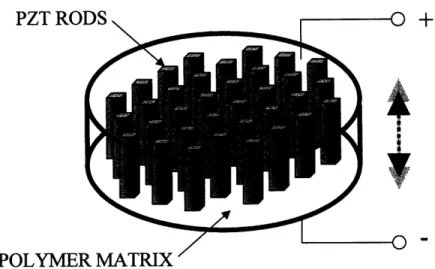
category of piezoelectric materials namely Piezocomposites. In the early 1980's, the Penn State Materials Research Laboratory of Penn State introduced a new type of piezoelectric material called 1-3 piezocomposites (Gururaja et al. 1980;Gururaja et al. 1984;Gururaja et al. 1985b;Gururaja et al. 1985c;Gururaja et al. 1985a;Shrout, Bowen, & Schulze 1980). These piezocomposite materials consist of small piezoelectric rods made typically of PZT embedded in a polymer or epoxy base (see Figure 1-3). The piezoelectric rods are equally spaced in two dimensionally periodic grid with varying fill ratios of polymer to active piezoelectric elements. This piezocomposite material possess significant advantageous over conventional PZT transducers. First, due to the compositenature (electrically active elements dispersed with non-conducting polymer) of the material, phased
array elements could be created by simply etching the electrode patterns as the polymer matrixprovides sufficient acoustic isolation between etched elements. Electrode etched piezocomposites make high-density arrays more practical than costly and labor intensive diced PZT ceramics.
Second, piezocomposites tend to be more polymer than hard PZT crystal rods, and with gentle heating, the transducer can be molded to deisred shape and size. Shaping of piezocomposites with heating is not only simpler but allows for more complex geometries than mechanical grinding of PZT pseudocrystal. Third, the small piezoelement rods embedded in the polymer contain appropriately narrow dimensioned rods to promote a single longitudinal vibrational mode even
when phased array element width approaches its thickness. With conventional PZT, the forward or
longitudinal transduction efficiency is significantly reduced if the element width-to-thickness ratio approaches unity as lateral modes are excited with the longitudinal modes (Desilets, Fraser, & Kino 1978). High-density phased array elements approach unity width-to-thickness ratios;therefore, high power high density arrays are not really feasible with PZT pseudocrystal. Fourth,
piezocomposites can be designed with multiple resonant frequencies allowing for a greater bandwidth than PZT or single crystal materials. Fifth, and probably most important to ultrasounddriving system design, the polymer/piezoelement combination has both lower electric and acoustic
impedance than their predecessor materials. Electrically, lower impedance can draw higher
currents for a fixed voltage thereby absorbing more electric power for acoustic energy transduction. Lower acoustic impedance allows the transducer to be more closely matched to the liquid coupling medium increasing the transducers ability transmit converted acoustic power intothe medium.
D7T fRnn
I L I kU TV
POLYMER MATRIX '
Figure 1-3. Diagram of a 1-3 composite piezoelectric. The rods represent the PZT and the fill
between the rods (not shown) is typically a polymer.
1.5.4 Ultrasound Driving Systems
Although there is a little published work on the early designs of ultrasound phased array
driving systems, most designs have used a switching amplifier with duty cycle control of power
(Buchanan & Hynynen 1994;Ebbini & Cain 1991a) and the use of counters or delay circuitry to
adjust the phase (Buchanan & Hynynen 1994;Lovejoy et al. 1995). The early systems lackedfeedback circuitry, so amplitude and phasing would drift and precise control of the focus was not
possible without corrections from a hydrophone at the focus. The current state of the art in therapeutic phased array driving systems utilizes a class D/E switching amplifier core with bothpower and phase feedback per channel to provide reliable fields without the need for hydrophone
corrections (Daum 1998). This multi-channel RF amplifier system has a frequency range of 0.5-0.9 MHz, 1-2 MHz or 2-2.5 MHz and is capable of providing up to 60 electrical watts per channel for up to 256 channels. These systems are adequate for high Q PZT phased arrays with relatively largeelements (much greater than
X/2)
but are not really scalable for large-scale phased arrays (hundreds
to thousands of elements) due to their high cost and large footprint per channel. In addition, piezocomposite arrays that are capable of being driven over a wide range of frequencies cannot befully utilized with tuned low bandwidth switching amplifiers. Thus, ultrasound driving systems are
currently the limiting factor in therapeutic phased array systems capable of optimal acoustic field control.1.6 Specific Aims
This research investigates cavitation in ultrasound therapy. In the first part of the study, a
new method for synergistically combining cavitation effects with thermal effects to improveultrasound ablation is investigated in animal models. Mechanisms of the enhanced effect as well as
monitoring techniques for the therapy are also studied. In the second phase of the research, techniques for controlling the cavitation field with phased arrays are explored theoretically. These techniques are to be utilized for not only our proposed cavitation therapy but for all applications where precise spatial and temporal control of cavitation is necessary. In the final phase of the thesis, a broadband phased array driving system capable of driving large-scale phased arrays and implementing the theorized cavitation field control is designed, constructed, and evaluated. Thisnew design will be a significant advance in therapeutic phased array technology making optimal
field control with precise selection of the ultrasound bioeffect possible.
1. 6.1 Cavitation-Enhanced
Ultrasound
Heating
In this initial study, we propose an ultrasound protocol that more reliably and predictably uses gas bubbles to enhance absorption and potentially deliver larger thermal doses in vivo. In these ultrasound exposures, we hoped to generate gas bubbles at the beginning of the sonication
and then immediately follow with conventional CW heating to utilize the region of enhanced
absorption. If tissue coagulation with this technique is primarily an enhanced thermal effect, MRI
thermometry and dosimetry could potentially be used for monitoring and planning of these
treatments. In order to trigger cavitation, a high intensity burst well above the cavitation threshold
was used, and for the CW ultrasound, conventional thermal mode power levels for typical FUSablation times were employed. In addition, visualization and monitoring methods for this heating
method were studied. MRI was used to select treatment locations, monitor temperature during treatment, and analyze the resulting lesions. Ultrasound monitoring techniques were used to detect the bubble activity. Previous experimental work has shown that the presence of oscillating and collapsing bubbles in an irradiated field correlates with detectable acoustic subharmonic emission.We employed this passive detection technique to monitor the presence or absence of bubble
activity during the burst phase of the sonication. In addition to being useful for monitoring, thesetwo monitoring techniques provided insight on the mechanism of bubble enhanced heating. If our
exposures generated enough bubbles to increase the ultrasound absorption at the focus, then larger
coagulated focal volumes without increased nearfield heating are possible. Ultimately, these larger
lesions created with a single ultrasound exposure may greatly improve the rate of tumor
coagulation.All experiments were performed under MRI (clinical, 1.5T) guidance with one of two eight sector, spherically curved piezoelectric transducers. The transducer, either a 1.1 or 1.7 MHz array, were driven by a multi-channel, RF driving system. The transducer was mounted in a MRI-compatible manual positioning system and the rabbit was situated on top of the system. An
ultrasound detector ring was fixed with the therapy transducer to monitor gas bubble activity
during treatment,. FUS exposures were delivered to 3 tissue types, muscle, fat, and interface, in the thighs of seven New Zealand white rabbits. The experimental, gas bubble-enhanced heating exposures consisted of a high amplitude 300 acoustic watt, half second pulse followed by either a 7 W, 14 W, or 21 W continuous wave exposure for 19.5 seconds. Prior to this study, cavitation thresholds in rabbit thigh tissue were measured at 1.1 and 1.7 MHz, for 100 and 500 millisecond exposures at 300 acoustic watts, a level significantly higher than the cavitation threshold. The respective control sonications were 20-second exposures of 14 W, 21 W, and 28 W. During the exposures, MR thermometry was obtained, and MR T2-enhanced imaging was used to evaluate the resulting lesions. Specific measures were used to evaluate the differences between the gas-bubble enhanced exposures and their respective control sonications: temperatures with respect to time and space, lesion size and shape, and correspondence with thermal dose predictions.
As the initial study showed promise, a second study to optimize the ultrasound parameters for cavitation enhanced (CE) heating, to understand the specific mechanisms of lesion formation and shape, to quantify the potential side effects, and to develop methods for monitoring and controlling this therapy was undertaken. Four different CE heating exposures were tested in vivo in an effort to find an optimal ultrasound exposure protocol. All of the exposures were initiated with a high intensity pulse to first induce gas bubbles at the focus. The initial burst was then followed by
constant power continuous wave (CW) ultrasound (similar to the initial study), pulsed ultrasound,
or a combination of CW with pulsed ultrasound. Different power levels for each of these exposures
were also studied. All of these exposures were monitored by MRI thermometry and simultaneouscavitation detection. Thermometry data in conjunction with cavitation spectrum at different time
points during the sonication were used to access the lesion formation process. MRI T2-weightedimaging was used to measure the lesion size, the primary end point in ultrasound therapy.
Additionally, various side effects of these CE heating exposures were also studied. From the monitoring techniques used in this study, the best metrics for the control of CE heating were assessed. Finally, the utility of cavitation and CE heating in concentrating energy at the focus andlimiting the ultrasound beams effects in the far field was also assessed. While performing the
ultrasound-enhanced heating exposures, the deposition of ultrasound energy in the farfield was
examined. Such effects could be used to shield vital tissues near the beam from being damaged,such as bone tissue near treatment locations.
1. 6.2 Theoretical
Determination of Optimal Cavitation Field
If cavitation methods are to be established in clinical therapy, precisely focusing the location
of cavitation is absolutely essential. Ectopic cavitation, that is cavitation outside of the target area,can cause unwanted heating or mechanical damage at locations in the nearfield of the transducer
away from the intended location. This in addition to the high variability of the cavitation threshold are the major deterrent to cavitation-mediated therapy. In the initial study, high acoustic intensity were used to induce cavitation. Unfortunately this requires large acoustic powers and appropriate transducers and amplifiers to supply these powers. In addition, since cavitation thresholds varyfrom point to point in tissue, locations near the focal point may exhibit cavitation yielding
undesired lesions. Ideally, if ultrasound powers could be lowered for cavitation inception and if the
cavitation threshold could be preferentially lowered at the transducer focus compared to other areas
in field, ectopic cavitation could be limited. In this study, various multi-frequency sinusoidalcombinations of acoustic pressure waves were tested on a non-linear bubble model to identify
waveform shapes that have lower cavitation thresholds. A bubble model incorporating rectified
diffusion was used to predict the cavitation threshold for a given waveform. The relative predicted
threshold for different waveforms were verified by controlled experiments. Once an optimal
waveform shape that would lower the cavitation threshold at the focus was determined, the
acoustic pressure field generated by spherically curved phased array transducer to yield that waveform at the focus was computed using the Rayleigh-Sommerfeld integral. The transducer's field was then analyzed to determine the relative cavitation threshold in the field (named the cavitation field) in terms of acoustic pressure and intensity. Parameters of the phased array excitation were varied in order to find cavitation fields in which the cavitation threshold was lowerat the focus than in the nearfield. These cavitation fields would limit the location of cavitation to the focus providing precise cavitation site control.
1.6.3 Ultrasound Phased Array System for Improved Acoustic and Cavitation Field Control
To practically implement the multi- frequency phased array therapy to optimally control the
cavitation location, both transducer and ultrasound driving system improvements need to be made.Till recently, ultrasound phased arrays used in therapy were high Q ceramics and did not respond
well at frequencies away from the resonance. Piezocomposite materials that are both broadbandand are capable of delivering therapeutic intensities are now available and have been developed in our laboratory. The RF driving system we currently employ for phased array therapy is capable of providing 60 electrical watts per channel for up to few hundred channels with very precise phase
control, but is limited to providing just one frequency of ultrasound in narrow RF frequency
ranges, 0.5-1 MHz, and 1-2 MHz. In addition the cost per channel is prohibitively high to makelarge-scale phased arrays practical.
In this study, a multi-frequency driving system for large-scale ultrasound phased arrays was developed. The design involves a multi-channel arbitrary waveform amplifier capable of providing 1-2 watts of electrical power per channel in the DC-10 MHz frequency range. This system was designed for transducers with 50 to 1000+ channels. A 50-channel easily scalable amplifier system
was constructed and tested with piezocomposite transducers. Field patterns suggested for cavitation
control were characterized in water. The proposed system will not only provide the driving technology for cavitation-enhanced therapy, but should significantly improve other focused ultrasound therapies.2 MRI-Guided Cavitation-Enhanced Ultrasound Heating
2.1
Introduction
In this chapter, we develop an ultrasound protocol that better uses gas bubbles to enhance
absorption and potentially deliver larger thermal doses in vivo. In this ultrasound exposure, we
hoped to generate gas bubbles at the beginning of the sonication and then immediately follow with
conventional CW heating to utilize the region of enhanced absorption. In order to trigger cavitation, a high intensity burst well above the cavitation threshold is used, and for the CW ultrasound, conventional thermal mode power levels for typical FUS ablation times were employed. In addition, visualization and monitoring methods for this heating method are studied. MRI was used to select treatment locations, monitor temperature during treatment, and analyze the resulting lesions. Ultrasound monitoring techniques are used to detect the bubble activity. Previousexperimental work has shown that the presence of oscillating and collapsing bubbles in an irradiated field correlates with detectable acoustic subharmonic emission (Atchley et al. 1988;Hynynen 1991b). We employed this passive detection technique to monitor the presence or absence of bubble activity during the burst phase of the sonication. If we are successful in
generating enough bubbles to increase the ultrasound absorption at the focus, then this technique
could result in larger coagulated focal volumes without increasing near field heating. Ultimately,
these larger lesions created with a single ultrasound exposure may greatly improve the rate oftumor coagulation.
2.2
Materials and Methods
2.2. 1 Experimental Apparatus
A schematic representation of the complete experimental setup is shown in Figure 2-1. The general apparatus included a focused ultrasound therapy transducer, a piezoceramic cavitation detector ring, and a manual positioner with animal coupling system all in a clinical MR imager. All measurement and controlling hardware was placed away from the large magnetic field in the adjacent MRI electronics room.
-I