HAL Id: hal-00782282
https://hal.archives-ouvertes.fr/hal-00782282
Submitted on 29 Jan 2013
HAL is a multi-disciplinary open access
archive for the deposit and dissemination of
sci-entific research documents, whether they are
pub-lished or not. The documents may come from
teaching and research institutions in France or
abroad, or from public or private research centers.
L’archive ouverte pluridisciplinaire HAL, est
destinée au dépôt et à la diffusion de documents
scientifiques de niveau recherche, publiés ou non,
émanant des établissements d’enseignement et de
recherche français ou étrangers, des laboratoires
publics ou privés.
Fast restoration of Connectivity for Wireless Sensor
Networks
Nourhene Maalel, Mounir Kellil, Pierre Roux, Abdelmadjid Bouabdallah
To cite this version:
Nourhene Maalel, Mounir Kellil, Pierre Roux, Abdelmadjid Bouabdallah. Fast restoration of
Con-nectivity for Wireless Sensor Networks. Conference on Next Generation Wired/Wireless Networking
(NEW2AN), Aug 2012, St Petersburg, Russia. pp 401-412, �10.1007/978-3-642-32686-8_37�.
�hal-00782282�
adfa, p. 1, 2011.
© Springer-Verlag Berlin Heidelberg 2011
Fast Restoration Of Connectivity
for Wireless Sensor Networks
Nourhene Maalel1 2, Mounir Kellil1, Pierre Roux1, Abdelmadjid Bouabdallah2 1Communicating Systems Laboratory
DRT/LIST/DIASI/LSC Gif sur Yvette, France
2Heudiasyc Laboratory, UMR CNRS 6599, UTC
Compiegne, France
1{name.surname}@cea.fr; 2[email protected]
Abstract. Node failures represent a fundamental problem in wireless sensor networks. Such failures may result in partitioned networks and lose of sensed information. A network recovery approach is thus necessary in order to ensure continuous network operations. In this paper, we propose CoMN2 a scalable and distributed approach for network recovery from node failures in wireless sensor networks. CoMN2 relies on a new concept called network mapping which consists in partitioning the network into several regions of increasing criticality. The criticality is set according to the energy, the traffic distribution and the deployment of nodes. Using this network mapping, our solution CoMN2 ensures the continuous network activity by efficiently swapping nodes from low critical area to highly critical area when required. Simulation results prove the effectiveness of our approach and show that the obtained improve-ment in terms of lifetime is in the order of 40%.
Keywords: WSN, fault tolerance, sensor failure
1
Introduction
Because of the unprecedented prospects they offer and the idea of eliminating human intervention, wireless sensor networks (WSNs) have perceived a tremendous attention from the research community in recent years [1]. Upon their deployment, WSN form a network composed of a set of sensor nodes and one or several sink nodes. Sensors role is to make measurement then to relay it as routers from sensor to sensor toward a sink node. We do also consider the presence of specific entity called mobile node which has the ability of processing data and making the appropriate decision. WSNs encounter many challenges [1] such as energy efficiency and limited battery. Our contribution focuses on the issue of sustainable connectivity.
Uneven energy distribution and consumption or accidental failures due to harsh envi-ronments may cause sensors to die arbitrarily [3]. These damaged nodes generate constrained region which provoke the network partitioning and thus hamper the net-work activity. On the other hand, the data traffic is typically concentrated on the sen-sor nodes surrounding the sink [4-5]. Consequently, those bottleneck nodes around the sink exhaust their batteries faster than other nodes which lead to the isolation of the sink from the rest of the network. Therefore, the network may get partitioned into disjoint areas (referred to as holes) due to node failure or energy depletion. If the net-work gets useless when the first holes occur, the remaining resources are wasted. Consequently, maintaining network connectivity is a crucial concern to ensure appli-cation operation.
In this paper, we exploit the non-uniform consumption, traffic distribution and dep-loyment of wireless sensors to elaborate an efficient dynamic recovery approach. We present CoMN2 a protocol restoring WSNs Connectivity using a Mobile Node in a Mapped Network. CoMN2 introduces a new concept called Network Mapping which consists in partitioning the network in several regions of increasing criticality. For instance a dense area with low sensing activity will have lower criticality than nodes in a sparse area highly solicited.
Through this network mapping, our solution CoMN2 ensures the continuous network activity by swapping nodes from low critical area to high critical ones when required. The swapping is performed using a mobile node which is aware of the sensor status. Basically, the algorithm is triggered depending on the Zone of the failed node in our mapped network. This solution minimizes the energy consumption by inhibiting the recovery process as long as the damaged node is not vital for the network. Above and beyond that, CoMN2 proceeds to a periodic network mapping update in response to unpredictable network dynamics.
CoMN2 design fulfills the following points that we consider as requirements for our context:
In view of the autonomous and unsupervised characteristics of WSN, the network recovery from node failure should be performed in a distributed manner.
The process should be rapid and lightweight to preserve the WSN respon-siveness to detected events.
The overheads should be minimized in order to consider the scarce resources of WSNs.
The remainder of this paper is organized as follows: the next section gives an over-view of the problem statement. The details of the algorithms and analysis are given section 3. Section 4 presents the previous approaches then section 5 provides the si-mulation results and finally section 6 concludes this paper.
2
Problem Statement
Maintaining inter-node connectivity is a crucial concern in WSNs. Many applications like disaster management require efficient and highly reliable nodes collaboration to efficiently assess damage and identify safe escape paths which emphasize the
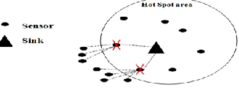
impor-tance of this concern. Basically, the failure of a sensor in critical region may create „holes‟ (Figure 1) and induces a partitioned network, so a reduction of the network operation efficiency. A particular case of this point is the HotSpot problem: Sensor nodes around the sink are extremely solicited to forward the sensed data (from the entire network nodes) toward the sink. In spite of the large deployment of sensors to tolerate possible node failures, we have to face the problem of isolation of the sink node caused by the depletion of the energy of sensor nodes surrounding it. This may result in the failure of the whole network whereas the remaining nodes are perfectly functional.
Fig. 1.Node isolation in the hotspot area
On the other hand, sensor nodes activity may be non-uniform in an hybrid network. For instance, regular traffic is expected for monitoring a given parameter whereas some nodes may be further involved in relaying data toward the sink. This non-uniform activity distribution depletes the battery of some sensors faster than the rest of the network.
Nevertheless, some areas are covered by excessive sensors which create redundant sensing region because closest nodes may have similar data [3]. Table 1 presents the relationship between the number of neighbors and the percentage of redundancy. As shown above, with 11 neighbors, the probability of complete redundancy is almost 92.28%, and the percentage of redundancy area exceeds 99%.
Table 1. Number of neighbors Vs Percentage of redundancy extracted from [3]
Number of neighbors Probability of complete redundancy Percentage of the redundant area
5 31.22-37.01% 91.62% 7 64.29-65.21% 96.89% 9 82.97-83.09% 98.85% 11 ≈ 92.28% 99.57%
Thus, the loss of a sensor in a redundant area does not impact the rest of the network because its neighbors are capable to achieve exactly the same role.
Keeping in mind all these aspects, our problem statement can be formulated as fol-lows: given a set of nodes,
How can we recover from node failure?
When should we replace the damaged node and which nodes are vital for the functioning of the network?
How can we handle unpredictable dynamics of the networks?
To deal with the first issue, CoMN2 proposes to recover from node failure by swap-ping nodes using a mobile node. This solution raises another issue which is the
selec-tion of the node to move. This problem is resolved thanks to a new concept proposed in this paper which is the network Mapping.
Upon the detection of a damaged node, CoMN2 considers four characteristics: The battery level
The number of neighbors
The location of the node (Hotspot area or not) The activity of the node
These issues are summarized in the ZoneAffectationTable which will be presented in the next section. Depending on the value of these parameters, the network is mapped in three zones of increasing rank expressing the criticality of sensors of each zone. This mapping is periodically updated to consider the network dynamism.
The detailed CoMN2 algorithm is explained in the next section.
3
CoMN2 Operation
3.1 Overview of the mechanism
In the following scenario, we are considering a hybrid WSN with static sensors, along with a sink and a mobile node. The mobile node is resource-rich node equipped with high processing capabilities and longer battery life. We assume that the sensors are randomly scattered over the network and that every node is aware of its location and its remaining energy.
The communication between sensors and the mobile node is performed thanks to the sink. All the control messages as initially sent to the sink which transfers it to the mobile node. We assume that the mobile node notifies the sink of its new position each time it moves.
As mentioned above, the crash of some nodes may stir up the division of the network into disjoint segments and leads to the formation of holes. To avoid this, our solution uses a mobile node carrying out the network restoration by switching a failed node with another from a redundant area (less critical). Furthermore, our solution handles simultaneous sparse node failure by classifying nodes according to their importance through an innovative process called network Mapping (partitioning). This method consists in organizing the network into three zones of increasing rank depending on the criticality of nodes belonging to each area. The detailed mechanism will be pre-sented in the following part.
3.2 Network Model
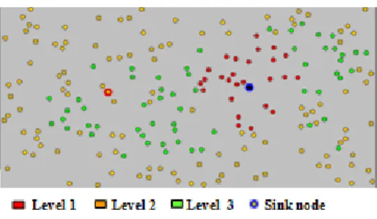
Our idea of mapping (Figure 2) the network emanates from the observation that sensors have no uniform activity in the network as explained in section II. The key plan is to hierarchically divide the sensor field into zones of increasing importance according to the node‟s activity.
Fig. 2. Network Mapping
In fact, the more the node is solicited, the faster its energy depletes and consequently it will die first. On the other side, some high density zones are monitored by excessive sensors what means that the failure of a node of that zone does not impact its func-tioning as stressed in section 3. That‟s why we decide to give priority to connectivity in specific zones instead of favoring connectivity of the entire network.
We divide the network into three zones of growing rank. Our basic assumption is that the nodes around the sink are the most actives [4-5] and that they belong to the first zone. Since we are considering a heterogeneous network with nodes assigned to di-verse applications, some nodes may be very solicited for sensing or reporting opera-tions. In view of their importance, the sensors of these specific zones belong to the first zone too. We define the third zone as the less critical one containing the set of nodes with more than 10 neighbors (section 3). The remaining nodes constitute the second zone. Finally we obtain a network‟s cartography based on how critical is each zone. This network cartography will be dynamic: it will be updated contingent on the activity of nodes.
3.3 Protocol Operation
Initial affectation of nodes through zones: The first affectation of nodes through
zones exploits their position and their neighborhood repartition. The mobile node will maintain a table referred to thereafter as ZoneAffectationTable containing five para-meters {Id, Pos, NN, RZ, Zone} where:
Id is a unique identifier of each node. Pos designate the local position of the node. NN is the number of neighbors.
RZ is a binary parameter designating risky zones: 1 for risky one/ 0 for no risky. Initially, RZ is set to 0 for all nodes. It will be set to 1 during the update process when the mobile node will notice the high activity of some nodes.
Zone indicates the zone of affection. It can be 1, 2 or 3 with 1 designating the most critical zone.
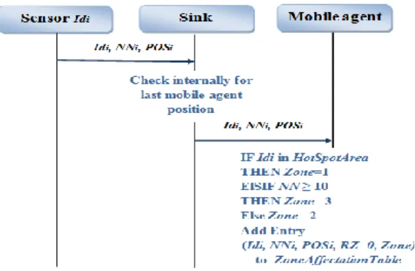
To establish ZoneAffectationTable, each node should send NN and Pos to the sink which will relay it to the mobile node (Figure 3). The whole process is kept local by requiring every node to maintain a list of only its close neighbors: we restrain our list to the 1-hop and 2-hop ones only.
Fig. 3. Initialization phase
After receiving this information from nodes, the mobile node would proceed to the zone affectation depending on the number of neighbors around each node:
Zone = 3 IF NN≥10 (1)
2 Otherwise
Nodes around the sink constitute the special case of the HotSpotArea. They are auto-matically affected to zone 1.
Update of the network mapping: CoMN2 pursues a dynamic approach by updating
the mapping of the network throughout the exchange of specific messages between nodes. This reorganization involves the refresh of the ZoneAffectationTable (Figure 4) and more precisely of NN and RZ.
NN is kept up to date by sending periodic HEARTBEAT messages between neighbor-ing nodes. The absence of HEARTBEAT response from a neighborneighbor-ing node F would mean that F failed then a message is automatically sent to the sink which will notify the mobile node. Upon receiving this notification, the mobile node modifies the value of the corresponding NN in the ZoneAffectationTable.
Furthermore, we define Tobs as the time that the sink waits before sending a periodic activity report to the mobile node for analysis. This report aims to determine the most solicited nodes by quantifying the number of operation (including sensing and routing) per node: each sensor is equipped with a counter which is incremented after every action like relaying or sensing data. The result of this counter is periodically sent to the sink. Keeping in mind that this report must characterize the network and is used to identify the most active zones, special attention is paid to well choose Tobs which should be long enough. Once the account is relayed by the sink, the mobile node calculates the average number of operations per node (the mean value) and sets RZ to 1 for the most solicited nodes: with a number of operations greater than the mean value. Thanks to this parameter, a node initially belonging to zone 3 can be classified as zone1 if it‟s highly active. Additionally, as soon as a node‟s energy drops below a critical level, it sends a DISTRESSMESSAGE containing its ID to the mobile node.
Fig. 4. Update phase
Initiation of the CoMN2 recovery process: To expound how CoMN2 Algorithm
performs, let‟s consider these two cases with a first classical one of a single alert mes-sage and a second case showing how our proposed algorithm handles simultaneous node failure.
Before giving rise to the recovery process upon detecting a failure, the mobile node waits during a period of Thold to check if there is another alert.
Single Alert
For the case of single alert, the mobile node should decide whether to initiate the re-covery or not. This choice is based on the zone to which the node belongs. Actually, the network mapping aims to avoid restoring connectivity at the cost of additional energy consumption when we can do without this node: The protocol tussles to mi-nimize the movement of the mobile node in order to save its energy. In fact, despite its high battery compared to the sensors, the energy of the mobile node is not unli-mited. Execution of restoration is triggered only if the node belongs to zone 1 or 2 which are the most important regions. If the dying node is from zone 3, we suppose that it has a sufficient number of close redundant neighbors to replace it. The mobile node checks at first ZoneAffectationTable to determine the Zone of the node then decide to rescue it or not.
Simultaneous Alert
Let‟s consider the case of 2 alerts received during Thold from node A in zone 1 and node B in zone 3. The mobile node proceeds to the comparison of the zone of each node using ZoneAffectationTable then decides to rescue the node with the most im-portant zone (which is node A in our example). If all the alerts arise from zone 3, no
recovery process is triggered because the failure of these nodes does not impact the efficiency of the network application. The case of simultaneous alerts with the same importance is handled by a FIFO mechanism (First In First Out). The mobile node continues its current task then deals with the second affected node.
Recovery execution: The recovery solution is based on the swap of nodes and the
replacement of the broken ones with the help of the mobile node. For the beginning of the network recovery approach, the mobile node exploits the Network Mapping to find the most suitable node to move. The choice of the best candidate is based on two criteria:
- A minimum change in the network topology. This condition can be achieved by choosing a node from a redundant area (zone3) which will not involve the reorganiza-tion of the network.
- The nearest one given the position of the failed node and the actual position of the mobile node in order to minimize the overhead of the recovery process.
The mobile node searches the closer node of zone 3 in the ZoneAffectationTable given the position of the failed node and his current position. This way, the inter-node con-nectivity is re-established without involving a change of the network topology. Since the spare node reaches the failed node location, it becomes responsible for carrying out its tasks including both routing and the application level. The choice of the optim-al path to reach the failed node is out of the scope of this paper.
4
Related works
How to deal with node failure is a challenging concern that has been widely studied in the past years. For instance, [12] proposed a power extension algorithm consisting on the increase of the transmission power to extend the communication range so that a node can reach further nodes when its next hop fails. This algorithm handles the con-nectivity aspect but does not provide a solution to ensure the sensing function of the failed node. Another proposed approach in [13] uses the neighbor information to con-struct a new path and take the routing role of the failed nodes. This work assumes that sufficient number of neighbors surround the failed node. Yet, this is not always true because of the random deployment of sensors in some scenarios such as hostile envi-ronments and hazardous zones.
Many researches investigate the use of mobile nodes [6-8] [14-15] to restore connec-tivity in mobile networks. In [7], the author suggests to use a mobile base station in order to load balance the charge around the sink by changing the nodes located close to it. Unlike our proposed approach, this algorithm restrains its efficiency on nodes surrounding the sink and involves an extra message overhead to update the location of the mobile base station. Another solution referred to as Coverage Conscious Connec-tivity Restoration algorithm [15] (C3R) relocates one or multiple neighbors of the failed node to recover from the damage. Each neighbor temporarily moves to substi-tute the failed node what leads to intermittent connectivity. The assumptions in the above work are strict because there is no guarantee to have multiple neighbors availa-ble.
Controlled mobility is a framework operating in context aware mobile devices with intelligent ability permitting to determine their future location on the basis of some
conditions like battery level or data gathered. Authors in [14] exploit controlled mo-bility to propose an algorithm for sensor nodes relocation. The algorithm assumes WSNs with cluster topology and allows relocation of sensor nodes between clusters based on predefined utility function. Despite its interest, this approach arises cluster-ing limitations such cluster head deployment and maintaincluster-ing coverage in clusters.
5
Experimental Evaluation
This section describes the simulation experiments to assess the effectiveness of the proposed approach. We compared CoMN2 to a Mobile Sink solution and to a basic topology without restoration.
5.1 Baseline approach:
We use two metrics to evaluate the performance of CoMN2: the network lifetime and the failure rate.
-The network lifetime is a generic term depending on the considered scenario. In our case, we define it as the time for the first node to become unable to reach the sink (no route available because of the failed nodes). Our goal is to increase the network life-time.
-The failure rate indicates the rate of failed nodes. It serves as a measure of the fault tolerance of the network: The higher the failure rate is at the end of the network life, the more fault-tolerant the network is.
A java simulator has been developed to evaluate CoMN2. The simulation experiments involve randomly generated WSN topologies with varying number of nodes from 100 to 800 in a network field with dimensions of 10000mx20000m. The location of the sink is selected randomly. For each topology set-up (network size, protocol) simula-tion is run 10 times and the average performance is reported. During each run, packets are generated and sent successively. The sending sensors are randomly selected and the path to the sink is created using least-cost routing in terms of number of hops. We assume the energy distribution is uniform in the network: all nodes have initially the same battery level. Nodes‟ battery-level decrease at each operation until attaining a critical threshold equivalent to 20% of the initial battery level. Once the threshold reached, CoMN2 is activated if the node belongs to zone 1 or 2 and the node is consi-dered as failed.
As explained in section 4, many researches propose solutions with Mobile Sink. Our simulation uses a configuration where the sink moves periodically in the network to load balance the traffic. It chooses a location where nodes in the neighborhood (nodes around the new position of the sink) have a high level of battery available.
5.2 Performance comparison
We conduct different experiment by varying the network density. To test the scalabili-ty of our approach, we increased progressively the number of nodes for a fixed net-work field dimension and transmission range. The results are depicted in Figure 5. As can be seen from the figure, our algorithm significantly increases the network lifetime
compared to the basic configuration (without restoration) and to the mobile sink for all network sizes. This rise is more significant for dense network which is attributed to the fact that the number of the back-up nodes used to replace the failed nodes in CoMN2 is higher in a dense network.
Fig. 5. Network Lifetime vs. Network size
Table 2 summarizes the increase of the network lifetime for the different configura-tions. We observe an average increase of more than 11% compared to the Mobile Sink and 40% compared to the network without CoMN2 which assess the effective-ness of our approach.
Table 2. Percentage of the network lifetime increase with CoMN2
Moreover, we tested the performance of CoMN2 in term of fault tolerance. Curves in Figure 6 shows that the fault tolerance is considerably raised thanks to CoMN2: the network tolerates a higher percentage of failed nodes (~35% vs ~10% without CoMN2).
Fig. 6. Fault tolerance vs. Network Size
Network Size % No CoMN2 %Mobile Sink
100 17,41 12,19 200 46,81 23,20 300 50,04 22,15 400 35,43 11,19 500 37,10 11,54 600 41,79 12,23 700 46,15 12,83 800 45,46 16,93 Without CoMN2 Mobile Sink CoMN2 Without CoMN2 Mobile Sink CoMN2
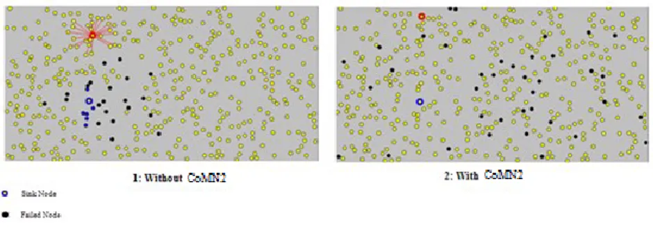
This increase is due to the location of the failed nodes which differs as shown in Fig-ure 7. We notice that unlike CoMN2, failed nodes are scattered around the sink for the first figure which shortens the network lifetime and provokes the hotspot problem.
Fig. 7. Failed node location for the same failure rate
In fact, the curves of failure rate vs. time for a network with and without CoMN2 follow the same slope (Figure 8) in the beginning of the simulation. Nevertheless, CoMN2 maintains nodes around the sink alive by swapping them with nodes far from it which increase the lifetime of the network. However, the hotspot area around the sink remains vulnerable to node failure (highly solicited) which increase its failure rate hence the higher slope of CoMN2 from t=500.
Fig. 8. Failure rate vs. Time
6
Conclusion & future works
Network mapping based on node resources represents an attractive paradigm in the design of wireless sensor network. In this paper, we presented a distributed and dy-namic recovery protocol CoMN2 which handles node failure in WSNs. As it is un-known whether such crash causes a network partitioning or not, we provide a tech-nique based on network mapping deciding if a node should be replaced or not. Simu-lations show that CoMN2 achieve more than 40% improvement of the network life-time.
For the future work, we plan to reduce the network recovery delay of our approach by investigating the optimal routing path to follow to join the sink.
CoMN2
REFERENCES
1. Ian F. Akyildiz, Ismail H. Kasimoglu, “Wireless Sensor and actor networks: Research Challenges,” Elsevier Ad hoc Network Journal, Vol. 2, pp. 351-367, 2004
2. I.F. Akyildiz, W. Su*, Y. Sankarasubramaniam, E. Cayirci., “Wireless sensor networks: a survey”, Computer Networks, Vol.38, , 2002.
3. K. Wu, Y. Gao, F. Li, and Y. Xiao, “Lightweight deploymentaware scheduling for wireless sensor networks,” Mobile Networks and applications, vol. 10, pp. 837–852, 2005. 4. Jaichandran J, Dr. A. Anthony Irudhayara, J. Emerson raja “Effective strategies and optimal solutions for Hot Spot Problem in wireless sensor networks (WSN)” Information Sciences Signal Processing and their Applications (ISSPA) pp389 – 392, 201
5. Jin Wang, Imanishimwe Jean de Dieu, Asturias De Leon Diego Jose, Sungyoung Lee, Young-Koo Lee; “Prolonging the Lifetime of Wireless Sensor Networks via Hotspot Analysis” Applications and the Internet (SAINT) 10th IEEE/IPSJ n 383-386, 2010 6. Vasanthi.v, Romen Kumar., Ajith Singh and M.Hemalatha, “A detailed study of mobility
model in wireless sensor networks” Journal of Theoretical and Applied Information Technology Vol. 33 No.1 ,2011
7. Jun Luo, J.P Hubaux, “Joint mobility and routing for lifetime elongation in wireless sensor networks” INFOCOM, 1735,1746 vol.3. 2005
8. Stefano Basagni · Alessio Carosi “Controlled sink mobility for prolonging wireless sensor networks lifetime » Journal of Wireless networks Vol14 pp831–858, Hingham, MA, USA 2008
9. S. Vemulapalli and K. Akkaya “Mobility-based Self Route Recovery from MultipleNode Failures in Mobile Sensor Networks”, WLN, Denver 2010
10. A. Efrat, S. Har-Peled, J.S.B. Mitchell, “Approximation algorithms for two optimal location problems in sensor networks”,Broadnets , Boston, MA, October 2005
11. You-Chiun Wang, Chun-Chi Hu, “Efficient Placement and Dispatch of Sensors” IEEE Trans on mobile computing ,tmc -0278-1006.R1 2007
12. C. Liang, X. Huang, and J. Deng, “A fault tolerant and energy efficient routing protocol for urban sensor networks,” in InfoScale ‟07: Proceedings of the 2nd international conference on Scalable information systems. ICST, Brussels, Belgium, Belgium, pp. 1–8 : ICST 2007.
13. D. An and H. Cam, “Route recovery with one-hop broadcast to bypass compromised nodes in wireless sensor networks,” in Wireless Communications and Networking Conference, WCNC, Kowloon ,pp. 2495–2500 ,March 2007,.
14. Daniel Denkovski, Aleksandra Mateska, Liljana Gavrilovska “Extension of the WSN Lifetime through Controlled Mobility”, The Seventh International Conference on Wireless On-demand Network Systems and Services IEEE/IFIP WONS, Kranjska Gora 2010 15. Tamboli, N.; Younis, M.;” Coverage-Aware Connectivity Restoration in Mobile Sensor