HAL Id: in2p3-00024947
http://hal.in2p3.fr/in2p3-00024947
Submitted on 27 Oct 2005
HAL is a multi-disciplinary open access
archive for the deposit and dissemination of
sci-entific research documents, whether they are
pub-lished or not. The documents may come from
teaching and research institutions in France or
abroad, or from public or private research centers.
L’archive ouverte pluridisciplinaire HAL, est
destinée au dépôt et à la diffusion de documents
scientifiques de niveau recherche, publiés ou non,
émanant des établissements d’enseignement et de
recherche français ou étrangers, des laboratoires
publics ou privés.
Beam dynamics studies in SPIRAL II LINAC
R. Duperrier, D. Uriot, N. Pichoff, P. Bertrand, B. Bru, A. Savalle, F.
Varenne, J.M. de Conto, E. Froidefond, J.L. Biarrotte
To cite this version:
R. Duperrier, D. Uriot, N. Pichoff, P. Bertrand, B. Bru, et al.. Beam dynamics studies in SPIRAL II
LINAC. 2003 Particle Accelerator Conference (PAC’03), May 2003, Portland, Oregon, United States.
pp.2802-2804. �in2p3-00024947�
BEAM DYNAMICS STUDIES IN SPIRAL 2 LINAC
R. Duperrier, D. Uriot, CEA Saclay, 91191 Gif sur Yvette; N. Pichoff , CEA Bruyères le Châtel, BP
12, 91680 Bruyères le Châtel; P. Bertrand, B. Bru, A. Savalle, F. Varenne, GANIL, BP 55027,
14076 Caen; J.-M. De Conto, E. Froidefond, LPSC, 38026 Grenoble; J.L. Biarotte, IPN, 91406
Orsay, France.
Abstract
The proposed LINAG driver for the SPIRAL 2 project aims to accelerate a 5-mA D+ beam up to 20 A.MeV and a 1-mA beam for q/A=1/3 up to 14.5 A.MeV. It is a continuous wave regime (cw), designed for maximum efficiency in the transmission of intense beams. It consists of an injector (two ECR sources + a Radio Frequency Quadrupole) followed by a superconducting section based on an array of independently phased cavities. This paper presents beams dynamics studies associated to the LINAG driver. End-to-end simulations (low-energy beam lines, RFQ, medium-energy beam line, SC linac) are shown.
INTRODUCTION
The possibility of a high-intensity accelerator at GANIL, producing secondary beams of unprecedented intensity, is considered. A project named SPIRAL 2 [1] is being under way presently in order to add medium-mass nuclei to those available with SPIRAL. In this project, fission induced by deuterons is proposed for the production of the radioactive ions, with the aim of at least 1013 fissions per second at least, with and without a converter. With the same linac, the SPIRAL 2 project aims to accelerate ions with q/A=1/3.
The linac consists of a double injector (two ECRs sources + a Radio Frequency Quadrupole) and a superconducting linac with independent resonators (QWRs and/or HWRs). The accelerating optimisation has to be performed for ions with q/A=1/3 (optimum β for the superconducting part). The input energy is 20 A.keV. This allows an extraction voltage of 60 kV (no platform). The output energy is set to 14.5 A.MeV for the 1-mA ions beam and to 20 A.MeV for the 5-mA deuterons beam. The input normalised rms emittances are 0.2 and 0.4 π.mm.mrad for deuterons and q/A = 1/3 ion respectively. It is assumed that this choice would give comfortable margins for such beam currents.
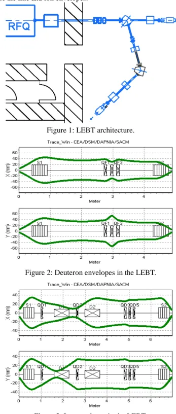
THE LEBT LINES
The LEBT for the D+ beam is mainly based on the use of 2 conventional solenoids and a quadrupole triplet, to transport and match the beam at the RFQ entrance. For this design, we need to take into account the installation of a LEBT that transports q/A = 1/3 ions to the same RFQ. Figure 1 shows the beam line architecture.
A possible transfer line has been studied considering a D+ beam for the over-estimated normalised RMS emittance of 0.2 π.mm.mrad. Figure 2 shows a possible
tuning for this line. A scheme for the heavier ion transport has also been studied and figure 3 presents the structure of the line and ion envelopes.
Figure 1: LEBT architecture.
Figure 2: Deuteron envelopes in the LEBT.
Figure 3: Ion envelopes in the LEBT.
0-7803-7739-9 ©2003 IEEE 2802
THE RFQ
The RFQ must operate in cw mode. Its frequency has been chosen to be 88 MHz, a sub-harmonic of 352 MHz. This rather low value has been determined for the following reasons: the RF power density is quite low at this frequency and allows a solution based on a formed-metal technology, leading to a cheap mechanical solution; at low frequencies, the inter-electrode distance is larger and permits a higher margin for the mechanical tolerances; power sources are readily available. The RFQ output energy, 0.75 A.MeV, has been determined by the fact that the first cavities of the SC linac must permit a possible evolution of the machine to ions with q/A = 1/6, which means that their β-values have to remain quite low (~0.07). The main RFQ parameters are described in the following table. The maximum peak field value is kept at a conservative level of 1.65 Kilpatrick [2], lower than LEDA [3] which also works in cw mode. The transverse curvature of the pole, ρ, has been maintained constant to simplify the machining (with a 2D tool).
Table 1: Main RFQ parameters
Parameters Values
Length 5.077 m
Minimum aperture (a) 1 cm → 0.55 cm Mean aperture (R0) 1 cm → 0.82 cm
Pole curvature (ρ) 0.75 cm Modulation (m) 1 - 2
Voltage 100 → 113 kV Peak field 1.65 Kp; 17.88 MV/m Synchronous phase - 90 deg→ - 30 deg
Beam dynamics calculations have been performed with the code TOUTATIS [4]. The transmissions are better than 99.9% for the ion beam and the deuteron beam. No transverse emittance growth is observed in the simulation. The longitudinal rms emittances are equal to 0.05 and 0.13 deg.MeV for the deuterons and the ions, respectively.
Monte Carlo simulations have been performed assuming mechanical tolerance of ± 0.1 mm on machining of the electrodes and ± 0.2 mm on misalignment. The results confirm that the deuteron beam transmission remains very close to 100% (only 5.10-5 loss rate). This gives quite a comfortable safety margin: losses of up to 3% have been considered for radioprotection purposes.
THE SC LINAC
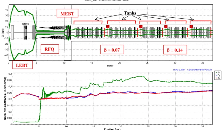
The superconducting linac is linked to the RFQ by a Medium Energy Beam Transport line (MEBT). Figure 4 shows the deuteron beam envelope and emittance behavior in the SPIRAL 2 linac. The MEBT includes the possibility to inject heavy ions coming from another RFQ. It contains two quadrupole triplets and two buncher cavities at 88 MHz. The linac must have the ability to accelerate with a maximum energy gain and must also be capable of being extended to accelerate heavy ions in future. It is based on independently phased superconducting resonators (QWR and/or HWR). Two families of β are used with a frequency of 88 MHz for the first one to ensure an efficient transition to the 88 MHz RFQ. The frequency of the second family is equal to 176 MHz to get a smooth transition to a possible future 352 MHz linac [5].
Figure 4 : Deuteron beam envelope and emittances behavior in the SPIRAL 2 linac LEBT RFQ MEBT β = 0.07 β = 0.14 Tanks 2803
The linac design is optimised with a routine that iterates through on possible geometrical β and transition β for the two families. The criterion to define the optimum β is the shortest linac with a minimum number of resonators. This process is performed with an (01) period for the first family and an (011) period for the second family where 0 is a solenoid and 1 a cavity. This lattice ensures a good efficiency of the cavities for this range of β. The resultant
β are 0.07 and 0.14 and the transition β is equal to 0.08 for an accelerating field, Eacc, equal to 8 MV/m. The first family requires 12 cavities (2 tanks) and the second one 18 cavities (3 tanks). A fallback solution has also been studied if it would turn out that this Eacc is too optimistic. An additional tank at the end of the linac would allow to decrease Eacc to 6.5 MV/m. The number of resonators then becomes 24 for the second family.
The beams dynamics have been performed with the codes TraceWin, PARTRAN [6] and LIONS_LINAC [7]. Emittance behaviour in the linac is shown in figure 4. All these codes are capable to use 3D field maps [8]. However, it is important to notice that the steering effect, induced by QWRs, is not included in the simulation shown by the figure 4. This problem is studied at present time using maps computed by SOPRANO [9]. The first studies show that vertical displacements are sufficient to reduce the emittance growth induced by the dependent phase deflection for the first family. For the second family, HWR may be used as a fallback solution if steering of 176 MHz QWR is too serious.
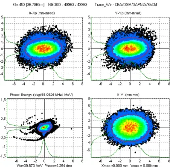
Figure 5: Deuterons beam in phase space at linac end.
The transmission of the superconducting part is 100%. For simulation of figure 4, the longitudinal emittance growth is around 30%. For the transverse plane, the emittance growth is 25%. Figure 5 shows the phase space portrait of the deuteron beam at the exit of the linac. It is clear that the longitudinal plane is the critical point at this stage of the study.
CONCLUSION
In the present paper, we have studied in detail technical aspects of the SPIRAL 2 linac. We have shown that a possible architecture can be found to reach the SPIRAL 2 goal. Meanwhile, several supplementary studies are required: use of 3D maps, correction of the steering effect induced by QWRs, correction scheme for the linac errors (BPMs and steerers), and definitions of the tolerances for construction.
REFERENCES
[1] A. Mosnier for the SPIRAL2 project team, “SPIRAL 2: A high intensity deuteron and ion linear accelerator for exotic beam production”, this conference.
[2] T.P. Wangler, “RF linear accelerator”, Wiley publishers.
[3] H. V. Smith and D. Schneider, “Status update on the Low Energy Demonstration Accelerator (LEDA)”, LINAC 98 conference, Chicago, p. 418.
[4] R. Duperrier, “TOUTATIS: a RFQ code”, Physical Review Special Topics Accelerators and Beams, December 2000.
[5] LINAG Phase I, a technical report, version 1.3, GANIL, june 27, 2002.
[6] N. Pichoff and D. Uriot, ″CEA Saclay codes review for high intensity linac″, ICCS conference, Amsterdam, 2002.
[7] P. Bertrand, “LIONS_LINAC: a new particle-in-cell code for linac”, this conference.
[8] D. Uriot and N. Pichoff, “New implement in TraceWin/PARTRAN codes: integration in external fields map”, this conference.
[9] www.vectorfields.com
2804