HAL Id: hal-02300516
https://hal.archives-ouvertes.fr/hal-02300516
Submitted on 29 Sep 2019HAL is a multi-disciplinary open access archive for the deposit and dissemination of sci-entific research documents, whether they are pub-lished or not. The documents may come from teaching and research institutions in France or abroad, or from public or private research centers.
L’archive ouverte pluridisciplinaire HAL, est destinée au dépôt et à la diffusion de documents scientifiques de niveau recherche, publiés ou non, émanant des établissements d’enseignement et de recherche français ou étrangers, des laboratoires publics ou privés.
Applications of full thermoplastic composite for type IV
70 MPa high pressure vessels
S Villalonga, C Thomas, C Nony, F. Thiebaud, M Geli, A Lucas, K Knobloch,
C Maugy
To cite this version:
S Villalonga, C Thomas, C Nony, F. Thiebaud, M Geli, et al.. Applications of full thermoplastic composite for type IV 70 MPa high pressure vessels. International Conference on Composite Materials, Aug 2011, Jeju Island, South Korea. �hal-02300516�
18TH INTERNATIONAL CONFERENCE ON COMPOSITE MATERIALS
1 General Introduction
The fossil resources shortage and climate change both encourage an evolution of our energy supplying system. For more than a decade, hydrogen as an alternative to traditional energy sources has been focus of research and development efforts. Hydrogen, combined with efficient converters such as fuel cells, represents a very promising way to realize a more sustainable energy system. Nowadays, for automotive applications, even if several interesting prototypes have been displayed, no storage system meets every international standards and car manufacturers’ requirements. However, developments on 700 bar type IV vessels with Thermoplastic PA6 liner [1][2] have demonstrated very encouraging results (cycling resistance, burst pressure, H2 tightness, gravimetric and volumetric storage capacities, H2 barrier properties). Over the last decade, the CEA (French Atomic Energy and Alternative Energies Commission) has developed, with several industrial and academic partners, valuable knowledge and competences focused on reactive rotational molding of high performances polymeric liners. The CEA has improved design, calculation, manufacturing and testing of structural composite vessel shells too. This paper reviews the most recent technical and scientific achievements in comparison with the state-of-the-art of CGH2 storage systems, especially results from the French collaborative research Hype project. Vessel composite shells are manufactured by filament winding using CarbosatmpTM (Toray T700 fiber, PA6 thermoplastic matrix). This paper presents the material used, its properties, composite and vessel design and calculation, manufacturing aspects, testing and automotive application.
2 Material
Considering gravimetric and volumetric densities, as well as safety requirements, type-IV vessels are the most promising solutions for on-board hydrogen storage. They display no fatigue issues, the H2 leakage is far below standards, and they show decent weight performances. CEA PA6 liner technology [3][4] has demonstrated abilities to withstand 15,000 cycles from 20 to 875 bar, as required by European or ISO standards for a nominal operating pressure of 700 bar. Moreover, the CEA is involved in the development of innovative materials such as materials for composite filament winding (thermoplastic and thermoset matrices) and materials for different types of liner (based either on thermoplastics and thermosets). In the scope of Hype project, the composite shell material, CarbostampTM ‘Fig.1’, is a polyamide matrix (polyamide 6) reinforced with T700 Carbon Fibers. Its fiber volume fraction is about 50 %. The material used for the liner is a PA6 thermoplastic material made by reactive rotomolding process so that the vessel is a PA6 monopolymer vessel with a very good consolidation between the liner wall and the composite shell. Thermoplastic matrix composites can be considered as relevant solutions since they present many advantages. They show numerous potential interests in term of storage, shell fiber volume fraction quality, impact resistance, durability and recyclability. Indeed, recyclability of CF/PA6 composite is easier than CF/Epoxy composite, which is very attractive for automotive industry. CF and PA6 can be separated by considering PA6 fusion temperature and re-used to make short carbon fibers for example. Moreover, CF/PA6 process could be less expensive and faster. Compared to epoxy prepreg which has to be stored at -20°C and used
APPLICATION OF FULL THERMOPLASTIC COMPOSITE FOR
TYPE IV 70MPA HIGH PRESSURE VESSELS
S. Villalonga1*, C. Thomas1, F. Nony1, F. Thiebaud2, M. Geli3, A. Lucas4, K. Kremer-Knobloch5, C. Maugy5
1
CEA, DAM, Le Ripault, F-37260 Monts, France, 2 MaHyTec, F-39100 Dole, France
3
TORAY-SOFICAR, F-64150 Abidos, France, 4 PARIS TECH, ENSAM, F-75013 Paris, France
5
PSA Peugeot Citroën, F-78307 Carrières sous Poissy, France.
Keywords: Thermoplastic Composite, Type IV High Pressure Vessel, Hydrogen Storage, Fuel Cell
before 6 months, there is no special constraint to store CF/PA6 before the filament winding. Compared to wet filament winding, there is no constraint of impregnation during the winding, no time and cost wasted to prepare resin, no pot-life time, no impregnation process parameters which need to be adjusted, no volumic fiber rate variation of the composite in the ply or in the laminate of the vessel, no time and cost wasted to clean the filament winding machine, no safety constraint (equipments and workers) as using volatile resin, no time and cost wasted due to the need of thermal curing after the filament winding process. The main difficulty of the CF/PA6 process (impregnation / consolidation / curing) is the consolidation step.
3 Material Properties
The design of reinforced laminated composites for type IV high pressure vessels application takes into account the initial mechanical properties of the material including safety coefficients [5].
CarbostampTM PA 6 is a polyamide matrix (polyamide 6) reinforced with T 700 Carbon Fibres from Toray SOFICAR. The fibre volume fraction, determined by pyrolysis at 500°C, is about 50 %. The matrix is semi crystalline and presents a melting point at 215°C. The density, measured according to Archimede’s principle by weighing the samples in air and a liquid of known density (water), is about 1.47 kg/m3 for CarbostampTM PA6.
The first characterizations are dedicated to the mechanical behavior of the material. Tensile tests have been conducted on unidirectional specimen with three different orientations 0°, 90° and 45° (orientations of fibres compared to the tensile load direction) and cross-plied laminates [±45]s. The test samples are manufactured by hot compression moulding. The materials and the mould are heated to reach a temperature above the melting temperature of the matrix. Then a pressure is applied. Finally the mould is cooled still under pressure to a temperature below the glass transition temperature before that the consolidated specimen is extracted.
The next mechanical experiments deal with different damages occurring in carbon fibers / polyamide matrix composite structures in the aim of understanding their influence on the mechanical
properties. Transverse cracking and delamination have been studied ‘Fig. 2’. The results are described in the following reference: [6].
4 Composite and Vessel Design and Calculation
The design of a composite vessel is extremely specific as it should take into account boss, liner and composite materials, liner manufacturing process specifications as well as constraints for the filament winding process. The composite architecture has to be optimized in order to approach the predefined target as closely as possible. Moreover, the design should take into account the service and test pressures, the external stresses, which are specific to the use (and dependent on, for instance, impact, aggressive media, temperature etc…). For the specific case of type-IV vessels, the main composite design test is the burst pressure.
Design of the dome shape region is one of the main difficulties for a high pressure vessel. The shape dome has to be compatible with the filament winding process. During the 18th century, the French mathematician Alexis Claude Clairaut (1713-1765) ‘Fig. 3.’ studied the geodesic shape on the earth surface [7] and developed a theorie. Today, this theorie is used to design and manufacture high pressure vessel by filament winding ‘Fig. 4.”. The best estimate calculation code for design evaluation has to be enough qualified to minimize result uncertainties and optimized High Pressure Vessels. In each case, HPV should be optimized to hold a maximum of fluid with a limited volume at the best manufacturing costs, load bearing capability and lifespan. This previous step is vital before enlarging design parameters and finally answering industrial and economic stakes.
Current finite element calculation limitations are related to different models and behavior uncertainties. We can quote for instance the following aspects:
- The lay-up design about the winding evolution strategies on end-closures revolution areas (thickness evolutions, angles evolutions with geodesic winding trajectories or with non-geodesic winding techniques, laminate superposition, slippage parameters)
3
APPLICATION OF FULL THERMOPLASTIC COMPOSITE FOR TYPE IV 70MPA HIGH PRESSURE VESSELS
- The finite element models about the choice of the elements types. Shell elements are mainly suitable for analyzing thin to moderately-thick shell structures whereas solid elements are more appropriate for calculation precision in spite of their more laborious use for winding mesh procedures, which could appears to be really time consuming in an optimization procedure where altering lay-ups is predominant. Another limitation concerns the accuracy of axisymmetrical models to faithfully characterize the composite cyclic periodic behavior. - The damage models. An optimization procedure has to take into account every damage mechanism (fatigue, failures…) occurring in the structure. The fatigue behavior for composite materials relies on the nature of the constituents, the process parameters and mainly on the application. - Numerous damage models for composites structures are available. For example, the most sophisticated one are based on micro-models [8] but are limited by their complexity and costs to relatively basic structures. Moreover, macro models [9], certainly more appropriate for more complicated and large structures, exist but still remain to be tested on pressure vessels.
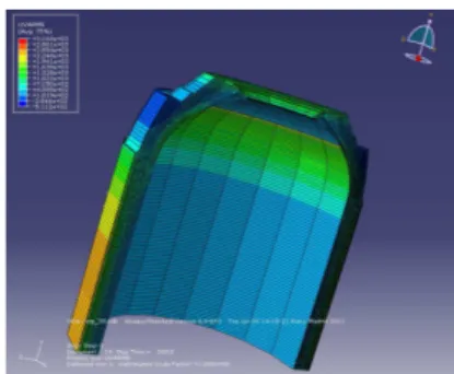
Today, the CEA is working on the qualification step of the FE calculation code for Type IV HPV design. For Hype vessel design, the laminate has been defined by using Abaqus Wound Composite plugin. The stress rupture analysis is compute by Abaqus code ‘Fig.5’.
5 Vessel Manufacturing
The liner is manufactured by reactive rotomolding process. The CEA developed, with it partner AIR LIQUIDE, a polyamide-6 (PA-6)-based polymer. A specific formulation was chosen based on the best compromise for permeation, mechanical strength, elasticity and processability. Since this polymer was sensitive to thermal oxidation, the CEA created an innovative 1-step reactive rotational molding process [3][4] starting directly from liquid monomers or precursors. The mold was considered to be a chemical synthesis reactor in which the polymerization and the shaping/molding occurred simultaneously. The polymerization took place between 150 and 180°C and lasted from 30 to 90 min depending on the size of the pieces ‘Fig. 6’ and eventually on the number of layers.
The composite shell is obtained by filament winding process. The filament winding process developed in this project presents a preheater (infrared), which raises the temperature just below the melting point, and a heater (infrared), which raises it above the melting point near the mandrel. The consolidation is ensured by a compaction roller. An adjustable tension is magnetically applied to T700/PA6 tape spools. Other heating systems have been evaluated as hot air system, laser system. Several PA6 liners with internal liner volume of 2 H2 liters, 37 H2 liters ‘Fig. 7’ have been winded with CarbostampTM PA6 with a good composite consolidation. 105 H2 liters will be winded during july 2011.
6 Vessel Testing
One of the main issues of project development is the characterization of vessels. Each CEA designs are validated in full-scale 700-bar H2 cylinders. Through liner polymer syntheses and formulation knowledge, reactive roto-molding and filament process capabilities, design and simulation methodologies, the CEA and its French partners have developed and fabricated a full PA6 thermoplastic type IV 700-bar vessel able of meeting the Hype project test criteria with regard to burst (>1,400 bar), permeation (<< 1 Ncm3/h/L) and cycling (>15,000 cycles). H2 standards are changing and safety factors are decreasing. Today, for the next ISO standard, considering automotive application, the burst pressure ratio could be 2.and, for the permeation, the maximum rate could be 6 Ncm3/h/L. At this stage of the project, MaHyTec partner is in charge of burst and cycling tests. The 37 L vessels will be tested in june 2011 and 105 L vessels in august 2011.
7 Automotive Application
High pressure hydrogen storage (700 bar) is one of the different hydrogen storage ways studied by PSA Peugeot Citroën, for its Fuel Cell vehicle. The FISYPAC Fuel Cell hybrid vehicle developed by PSA in 2009 ‘Fig.8’ was already equipped with high pressure 700 bar H2 type III tanks. One of the main challenges for high pressure H2 storage system is to increase system’s volumetric and gravimetric capacities. HYPE tanks are aimed at answering those requirements.
Fig.1. Toray-Soficar CarbostampTM. Transverse cracks (loading between 200 and 600 MPa) Longitudinal cracks (loading up to 700 MPa) Delaminating (loading up to 700 MPa)
Fig. 2.CarbostampTM Ply Damages
Fig.3. French Mathematician Alexis Claude Clairaut (1713-1765)
Dome geodesic profiles for High Pressure Vessel
0 0,2 0,4 0,6 0,8 1 0 0,2 0,4 0,6 0,8 1 radius d o m e l e n g th 6 9 12 14 17 20 24 27 30 33 37 41 44
Fig.4. Dome Geodesic profiles for HPV
Fig.5. Abaqus stress distribution in composite shell
Fig.6. CEA 37L PA6 Liner
Fig.7. 37 liter 70MPa Type IV Vessel (PA6 Liner, CarbostampTM Composite shell).
5
APPLICATION OF FULL THERMOPLASTIC COMPOSITE FOR TYPE IV 70MPA HIGH PRESSURE VESSELS
Acknowledgment : This work has been supported
by French Research National Agency (ANR) through “Plan d’Action National sur l’Hydrogène et les piles à combustible” program (ANR-07-PANH-006-02).
6 References
[1] F. Nony & al.., “Type IV 700 bar-vessel for compressed gaseous hydrogen storage: Material
research and performance achievements”,
WHEC2008, Brisbane, Australia, 2008.
[2] S. Villalonga & al.., “Composite 700 bar-vessel for on-board compressed gaseous hydrogen storage”, ICCM 17, Edinburgh, United Kingdom, 2009. [3] P. Mazabraud, Commissariat à l’Energie Atomique,
Patent n° FR0451104, 2004.
[4] P. Mazabraud, Commissariat à l’Energie Atomique, Patent n° FR0553585, 2005.
[5] C. Thomas & al.., “Study of damages on
thermoplastic composite structures: application for hydrogen storage vessels under high pressure”, JNC16, Toulouse, France, 2009.
[6] C. Thomas & al.., “Research and achievements on carbon fiber reinforced thermoplastic composites for high pressure storage”, PVP 2011, Baltimore, USA, 2011.
[7] A. C. Clairaut, “Theorie de la figure de la terre”, David Fils, Paris, France.
[8] Mishnaevsky Jr, L. and Brondsted, P.,
“Micromechanical modeling of damage and fracture of unidirectional fiber reinforced composites: A review,” Computational Materials Science, 44(4), pp. 1351-1359, 2009.
[9] Spottswood, S.M., and Palazotto, A.N., “Progressive failure analysis of a composite shell,” Composite Structures, 53(1), PP. 117-131, 2001.