HAL Id: hal-00874210
https://hal-iogs.archives-ouvertes.fr/hal-00874210
Submitted on 17 Oct 2013
HAL is a multi-disciplinary open access
archive for the deposit and dissemination of
sci-entific research documents, whether they are
pub-lished or not. The documents may come from
teaching and research institutions in France or
abroad, or from public or private research centers.
L’archive ouverte pluridisciplinaire HAL, est
destinée au dépôt et à la diffusion de documents
scientifiques de niveau recherche, publiés ou non,
émanant des établissements d’enseignement et de
recherche français ou étrangers, des laboratoires
publics ou privés.
Large-field high-resolution X-ray microscope for
studying laser plasmas
Richard Sauneuf, Jean-Michel Dalmasso, Thierry Jalinaud, Jean-Pierre Le
Breton, Daniel Schirmann, Jean-Paul Marioge, Françoise Bridou, Gérard
Tissot, Jean-Yves Clotaire
To cite this version:
Richard Sauneuf, Jean-Michel Dalmasso, Thierry Jalinaud, Jean-Pierre Le Breton, Daniel Schirmann,
et al.. Large-field high-resolution X-ray microscope for studying laser plasmas. Review of Scientific
Instruments, American Institute of Physics, 1997, 68 (9), pp.3412-3420. �10.1063/1.1148302�.
�hal-00874210�
Large-field high-resolution x-ray microscope for studying laser plasmas
Richard Sauneuf, Jean-Michel Dalmasso, Thierry Jalinaud, and Jean-Pierre Le Breton
Commissariat a` l’Energie Atomique (CEA)/Limeil-Valenton, 94195 Villeneuve St-Georges Cedex, France
Daniel Schirmann
Commissariat a` l’Energie Atomique (CEA)/Bruye`res-le-Chaˆtel, BP 12, 91680 Bruye`res-le-Chaˆtel, France
Jean-Paul Marioge, Franc¸oise Bridou, Ge´rard Tissot, and Jean-Yves Clotaire
Institut d’Optique The´orique et Applique´e (IOTA), Batiment 503, Centre scientifique d’Orsay, BP 147, 91403 Orsay Cedex, France
~Received 9 September 1996; accepted for publication 13 June 1997!
In 1948, P. Kirkpatrick and A. V. Baez developed an x-ray microscope~energy range about 100 eV–10 keV! composed of two concave spherical mirrors working at grazing incidence. That device, named KB microscope, presents a 3–5mm resolution within a field having a radius about 100mm; outside that field, its resolution lowers rapidly when the object point recedes from the center. The adjunction of two similar mirrors can notably increase the useful field~typically, the resolution can be better than 10 mm within a 2-mm-diam field of view!, which is necessary for studying laser plasmas. Its main advantage with respect to more simple optics, as the pinhole, is that it can be located far enough from the plasma to avoid any destruction during the shot. We describe such a microscope that we call KBA microscope and present some images of fine metallic grids. Those grids were backlighted by x-ray sources, either a cw one or a series of laser plasmas from the Octal–He´liotrope facility. Examining the films in detail shows that the experimental results are very close to the theoretical characteristics; hence the interest of this device for the x-ray diagnostics on the future powerful laser facilities. © 1997 American Institute of Physics.
@S0034-6748~97!02609-9#
I. INTRODUCTION
The very hot and very dense plasmas created by laser ~more simply called laser plasmas! in order to achieve iner-tial confinement fusion~ICF! have small dimensions ~a few mm, even less than 1 mm! and a very short duration ~a few ns!. Moreover, they include phenomena that are often unde-sirable such as instabilities the typical dimensions of which are in the order of a few microns. When we want to study these phenomena, we need to have high resolution optical devices able to work in the x-ray range; for our needs, this range spreads from about 100 eV–10 keV or even a little more.
As a matter of fact, those plasmas emit radiations the spectrum of which presents a maximum within this range; in other respects, when we want to probe those very dense plas-mas~x-ray backlighting!, we must use x rays having energies lying in the same range. The desired resolution is in the order of a few microns, if possible about 1mm. So the magnifica-tion must be 10–50 to match the resolumagnifica-tion of high speed detectors as streak cameras or shutter tubes~10–20 lp/mm!. When we want to make images with x rays having en-ergies of about 1 keV, the best known optical devices are those which use x-ray glancing reflection on mirrors; the value of the glancing angle u is a few degrees, sometimes even lower than 1°.
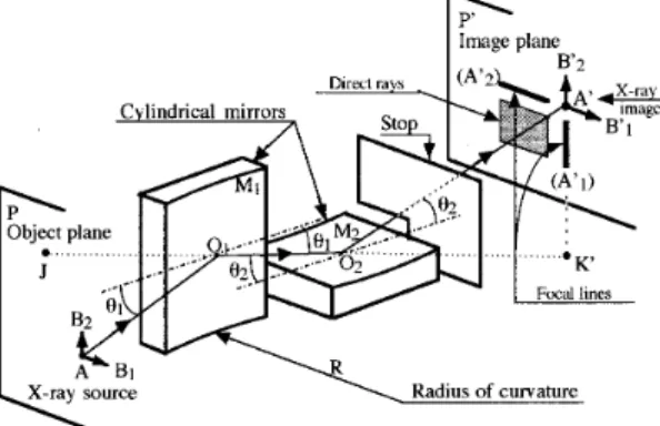
A device made up of two ‘‘crossed’’ concave spherical mirrors~the incidence planes of the mirrors are perpendicular to one another! was developed in 1948 by Kirkpatrick and Baez1 ~Fig. 1!. This arrangement of mirrors overcomes the strong astigmatism produced by a single concave mirror used
at grazing incidence. The rays coming from the object point
A and reflected successively by the two mirrors make a
pen-cil which is focused to a small spot, (A
8
), centered on pointA
8
. This spot is generally small enough to be considered as a satisfactory image of A; so we can say that A8
is the image of A. The broken line AO1O2A8
, composed of the succes-sive mean rays, is called the pseudo axis of the system. Ob-ject and image planes, P and P8
are, respectively, perpen-dicular to the segments AO1 and O2A8
. We also call meanplane of incidence for M1 ~or more simply M1 incidence
plane!, the plane I1 containing the segment O1O2 and the normal at O1 to the mirror M1; M2 incidence plane is de-fined in the same way and named I2. O1 and O2 will be called the apex of their respective mirror.
The previous authors showed that the radius of curvature of both mirrors is very large with respect to the distance between the object and the microscope and that each mirror is equivalent to a cylindrical one having the same radius; so, in order to make their representation easier, we will replace the spherical mirrors by cylindrical ones or even by planes.
Such a device is currently called a KB microscope and is used in many laboratories2 to realize images of laser plas-mas. However, if the KB microscope can achieve a few mi-cron resolution, this can only be obtained in a rather small field, due to the field obliquity of this device. In order to get a larger field of view, we calculated and realized a similar microscope using four mirrors instead of two; we call that device a KBA microscope ~from French ‘‘KB aIme´liore´’’ meaning ‘‘improved KB microscope’’!.
This microscope had to satisfy to the following charac-teristics:
~i! mean magnification: 10;
~ii! distance from the object to the microscope entrance: 200 mm;
~iii! distance from the object to the image: about 2.7 m; ~iv! mean grazing angle on each surface: about 2°~cut-off
energy on silica mirrors '860 eV!; ~v! total solid angle of collection: about 4 msr;
~vi! resolution at 100 eV better than: 10mm within a field having a radius of 1 mm, 30mm within a field having a radius of 2 mm.
We will see later that the characteristics of the com-pleted optical system will be very close to the desired ones.
II. OPTICAL CONSIDERATIONS A. Field obliquity
A spherical mirror used at grazing incidence gives a fo-cal surface which is strongly inclined to the normal of the principal ray. The inclination of that surface depends on the position of the aperture stop and would be cancelled if a real stop could be placed at a distance of about 2 f /3 from the mirror on the image side. But in the case of the KB micro-scope, that stop would be difficult to adjust; so the aperture stop is the mirror itself in each plane of focusing.
In one plane of incidence the ray tracing is shown in Fig. 2. Let us consider the image formation of a small object AB, situated in this plane and in the object plane, then perpen-dicular to AO. The aperture of the incident and reflected bundles is small so the geometrical aberrations are low and the image A
8
of the point A is a small segment that can be considered as a point if its dimension is lower than the de-sired resolution.On the pseudo-axis, we choose O as origin and the light propagation as positive direction. The location of the points
A and A
8
is given by the formula:1/p
8
21/p51/f , ~1!where
p5AO, p
8
5OA8
and
f5~R sinu0!/2
'Ru0/2 ~because u0 is generally small!, ~2!
R being positive for a concave mirror and negative for a
convex one,ubeing always supposed positive.~uis the gen-eral name of the grazing angle between any ray and the mir-ror; sometimes it may be followed by a subscript to indicate a particular angle asu0 in the previous relation!.
If we consider point B, the preceding relations show that its image B
9
is not in the plane P8
because u is different from u0 when p is fixed; so p8
has also varied. A8
B9
incli-nation is very important: the anglebis aboutu0p/ p8
. This is the field obliquity aberration which cannot be corrected in the common KB microscope.The pencil of rays that converges to B
9
has a very small aperture and its intersection (B8
) with the plane P8
is a little spot centered in B8
. As long as the dimension of this spot is lower than the desired resolution, B8
can be considered as the image of B and the segment of line A8
B8
as the image ofAB. Within this approximation, the magnification given by
one mirror is defined by the formula:
G5y
8
/ y , ~3!where y5AB and y
8
5A8
B8
, with their algebraic signs~see Fig. 2!.It can be easily seen that the magnification becomes
G52p
8
/ p. ~4!In these relations, p, p
8
, and G are algebraic values. Afterwards we will often use the same symbols with the meaning of absolute values; the context will then permit one to understand their meaning.In the KB system~Fig. 1!, a small object AB located in the plane P may be considered as a vector having, in P, two components AB1 and AB2, respectively, parallel to the inci-dence planes I1 and I2. Then everything works as if the mirror M1 acted only on the component AB1 to form the image A
8
B18
with the magnification G1 defined in ~3!, the part played by the other mirror being to refocus the diverging rays coming from each point of AB1 and situated in inci-dence planes close to I2. By reversing the parts of the twoFIG. 1. Schematic arrangement of the Kirkpatrick–Baez microscope which is made of two ‘‘crossed’’ spherical~or cylindrical! mirrors, M1and M2,
used at grazing incidence. The image of the point A in the object plane P is
A8in the image plane P8. The image of B1, another point of P, not too far
from A, is not in P8~see Fig. 2! but the intersection of the reflected pencil with P8is a small spot, nearly circular, centered in B18~the aperture of the
incident and reflected pencils is very small!. As long as the spot diameter is lower than the desired resolution, we can say that B18is the image of B1.
FIG. 2. Image formation of a small object by a spherical mirror working at grazing incidence: the image is affected by the field obliquity aberration. The drawing displays the ray tracing in the incidence plane of the mirror. The focal distance is proportional to the angleubetween the mirror and the incident ray. For B it is greater than for A, so the image of AB is A8B9, with
B9far outside from P8~bis a very small angle!. Nevertheless we consider that A8B8, situated in P8, is the image of AB if AB is small enough.
3413 Rev. Sci. Instrum., Vol. 68, No. 9, September 1997 X-ray microscope
mirrors, M1 gives the image A
8
B28
with the magnificationG2. The image A
8
B8
is then the sum of the two componentsA
8
B18
and A8
B28
.With a good approximation, we can use the following relations:
1/pi
8
21/pi51/fi with fi5Riui/2 ~5! andGi52pi
8
/ pi, ~6!where i can take the values 1 or 2, piand pi
8
representing the algebraic distances along the broken lines joining Oi to A and A8
. If we call d the algebraic value of O1O2, we can write:p1
8
5p28
1d and p25p12d.We can see that the magnifications in the two directions are not equal (G1.G2) so the image suffers a distortion called anamorphotism; this distortion is not a problem be-cause it is now easy to correct it by digital processing.
B. Aperture of the optical system
The incident pencil coming from A~as well as the pencil that leaves the microscope and converges to A
8
) has the form of a pyramid with a nearly rectangular base. To show it more easily, we suppose ~Fig. 3! that M1 is a cylindrical mirror perpendicular to the plane I1 ~M1 incidence plane! and limited by the two generating lines (S1) and (T1); the distance L1 between those lines is called the length of M1. In the same way, M2is a cylindrical mirror perpendicular to the plane I2 ~M2 incidence plane! and limited by the two generating lines (S2) and (T2); the distance L2 between those lines is the length of M2.The rays emitted by A and reflected by M1 converge to the line (K
8
) perpendicular to I1 at the point K8
~symmetri-cal to A8
with respect to M2! and are located inside thedihedral angle defined by A and the edges (S1) and (T1). In the plane I1, represented in Fig. 3~a!, we can see that its value is:
a15~L1 sinu1!/p1 ~a1 is a small angle!.
In the same way, the reflected rays are included inside the dihedral angle defined by (K
8
) and the edges (S1) and (T1); its value isa1
8
5~L1 sinu1!/p18
.Only a part of the previous rays strikes the second mir-ror. In Fig. 3~b!, we see that the useful rays are limited by dihedral angles~valuesa2 anda2
8
! perpendicular to the pre-vious ones. The intersections of those dihedral angles are two pyramids with rectangular bases.The aperture angles of the incident pencil ~a1 anda2! and those of the emerging one~a1
8
anda28
! are then, respec-tively, limited by the mirror lengths L1 and L2 according to the relations:ai5~Li sinui!/pi, ~7a!
ai
8
5~Li sinui!/pi8
, ~7b! which give the following relations:ai
8
/ai5pi/ pi8
51/Gi. ~8! As L1'L2'L andu1'u2'u, we will have:a1'a2'a and a1
8
'a28
'a8
so the pyramids will generally be replaced by cones with apex angle a or a
8
~for instance, in the calculation of dif-fraction!.III. KBA CONCEPTION
A. Reduction of field obliquity
We have just seen that the image A
8
B9
of a small objectAB is strongly inclined because of the variation ofufrom A to B ~Fig. 2!. The angle between the incident and reflected mean rays is 2u0 for point A and 2(u01e) for point B. By using a system with two parallel mirrors ~both mirrors have the same incidence plane! as suggested by Dyson,3 we see ~Fig. 4! that the angle between the incident and reflected
FIG. 3. Aperture of the KB microscope. This schematic drawing displays two views of the optical system~made of two cylindrical mirrors for helping the understanding!: ~a! a view in M1incidence plane, I1, which cuts M1
according to the segment S1T1 and M2 according to the line (O2); ~b! a
similar view in M2incidence plane, I2. We can see that the incident pencil
coming from A is limited by the generating lines (S1) and (T1) of M1; the
aperture of the pencil in I1isa1. Within the pencil reflected by M1only a
small part can reach M2; this part is limited by the generating lines (S2) and
(T2) of M2; the aperture of the pencil in I2isa2.
FIG. 4. The association of two ‘‘parallel’’ mirrors ~they have the same incidence plane! cancels the field obliquity aberration; we call that associa-tion a ‘‘bimirror.’’ The drawing displays the ray tracing in the bimirror incidence plane and shows the invariable anglehbetween the mirrors. We see that the angle between AO1and O2A8has the same value~2h! than the
angle between BO1 and O2B8; it suggests that the focal distance of the
system is nearly the same for both points A and B and explains the cancel-ing of the field obliquity.
mean rays is always the same, 2h, whereh5u11u2 is the angle between the two mirrors. We may then think that the focal distance of the system will be nearly the same for A or
B.
As a matter of fact, by making slight approximations, we can calculate the focal distance of such a system. For prac-tical and theoreprac-tical considerations, we will consider the sim-plest device made up of two parallel mirrors with the same curvature radius R and the same mean grazing angle u 5h/2; moreover they are joined side by side in order to minimize the distance e5O1O2. We will call this device a
bimirror; its focal distance is practically constant for any
point B near to A in the object plane P and its value is
w5Rh~112e/Rh!/8. ~9a!
As e!Rh, we can write more simply:
w5Rh/8. ~9b!
B. Correction of astigmatism
It is clear that a bimirror has the same astigmatism as a simple mirror but that shortcoming can be corrected by the use of two crossed bimirrors; this system will then have a high resolution within a rather large field. In order to facili-tate the future explanations, we will say that the first bimirror is vertical~its incidence plane being horizontal! and the sec-ond one is ‘‘horizontal’’ because its incidence plane is ver-tical.
This optical system is then composed of four successive mirrors ~Fig. 5! and its pseudo-axis is the broken line
AO1O2O3O4A
8
. LetO1O25e1, O3O45e2, O2O35d,
O1A5p1, O4A
8
5p48
.This optical system can be defined by desired values of: ~i! the object to image distance;
~ii! the mean value of magnifications; ~iii! the mean value of grazing angles; ~iv! the aperture of the microscope.
Starting from those data and using relations~5!–~7!, we can calculate approximate values of p1, e1, e2, d, and p4
8
, magnifications G1and G2, lengths of mirrors, as well as the focal distancesw1andw2of each bimirror. Then we have to choose either R15R2, which facilitate the figuring of the four mirrors which will have the same radius of curvature;henceh2Þh1; orh25h1, which can give the same spectral response for each mirror and may be necessary when the four mirrors are all together coated with a multilayer; hence R1 ÞR2.
To calculate a more precise value of the above param-eters we have to take into account the field influence which leads to making longer one of the mirrors of each bimirror; we must also use the exact astigmatism relations that include the presence of sagittal and tangential focal lines for each mirror. That leads to an iterative calculation by computer.
C. Field influence in a bimirror
As for the KB microscope, the aperture stop is one mir-ror of each bimirmir-ror; we call it the aperture mirmir-ror. The other one, called field mirror, is longer than the aperture one to avoid loosing a part of the pencil when the object point shifts from one edge of the field to the other one ~Fig. 6!.
Relative location of the two mirrors is then determined as follows:
• The aperture mirror, M2, the apex of which is O2, is placed behind the field mirror M1 and the mean incident ray strikes M1 at O1. The variation of the field angle is then lower than if the aperture mirror was the first one; calcula-tions show that the resolution variation is also lower.
• The mirrors M1 and M2 are joined side by side at the point O; in order that M2 be actually the aperture mirror, it is slightly shifted with respect to M1 on which there will be a little ‘‘dead’’ area OJ2 in the vicinity of M2. The figure shows that if the shift is low, O1 is not at the center of the mirror M1; for the ease of assembling, we chose to put O1at the center of the mirror; hence the shift and the dead area are a little more important but still reasonable.
D. Assembling and adjustment principles
We imagined a device in which the x-ray mirrors would be held and positioned by steel parts work-finished by a grinding machine. The expected tolerances are 5mm for the essential sizes and 20
9
for the angles; we will see that they are sufficient. On the other hand, x-ray mirrors would be figured by optical polishing.We also had to take into account the way of using and adjusting this microscope which is implemented in a me-chanical device~we call it optical unit! that can be fixed on one port of the laser chamber~it will be called output port!.
FIG. 5. Schematic arrangement of the KBA microscope. It is composed of two bimirrors which are crossed in order to cancel the astigmatism of a single bimirror.
FIG. 6. Field influence in a bimirror. In the KB microscope each mirror plays the part of an aperture stop. In a bimirror, only one mirror must play that part. We chose the second one as the aperture mirror, so the first one
~field mirror! had to be longer to allow rays coming from the edges of the
desired field~B1and B2! to strike M2after reflection on M1. The
theoret-ical length of M1is J1J2but the mirror is made a little longer.
3415 Rev. Sci. Instrum., Vol. 68, No. 9, September 1997 X-ray microscope
That device gives the microscope three orthogonal motions of translation under vacuum; a longitudinal one, X, along the direction of ray propagation; the other two motions are trans-verse: Y is horizontal and Z is vertical. Those motions are controlled by step motors and electronic units. At the atmo-spheric pressure, we can adjust its orientation by means of two knobs.
To obtain the best image, the pseudo-axis must be aligned on the object center. This pseudo-axis is materialized by the normal to the auxiliary plane mirror, M0, at the center of a small hole (B2 mm), the x-ray input hole, drilled in this mirror~Fig. 7! which is just located in front of M1; M0 protects the x-ray mirrors and the hole in it limits the inci-dent bundle to avoid undesirable illuminations on the detec-tor.
On laser chambers, we can always put a small object at the point that we call the ‘‘center’’ of the chamber. We can also materialize the interesting axis of the chamber by an auxiliary continuous wave laser; its beam is set perpendicu-lar to the plane of the desired port and goes through a pin-hole (B'0.3 mm) located at the chamber center. The mi-croscope is then tilted so as to make M0perpendicular to the beam. We have now to move the microscope until the beam goes through the center of the input hole but it is not as easy as it seems. We prefer to make the beam go through an auxiliary pinhole (B'0.3 mm) bored in a rather thin metal-lic foil stuck at one end of a small tube which is set in another hole ~adjustment hole! in M0 ~the pinhole is per-fectly centered on the axis of the adjustment hole!. Behind that pinhole we can see the resulting diffraction pattern and when it is made of well concentric circles, we are sure that the alignment is good with a 60.05 mm accuracy. After-wards we only have to move the microscope by known amounts in the Y and Z directions to be sure that it is well adjusted.
As the focusing depth is rather large ~61 mm for an increase of 2 mm of the resolution limit in the field center!, the distance between the object and the microscope can be monitored by a simple ruler.
IV. RESULTS OF COMPUTATION
A. Radius of curvature and magnification
In order to facilitate the figuring of mirrors with large radius of curvature and the radius measurement, we decided that the four mirrors would have the same radius R. Using the classical astigmatism relations, the results of computation are as follows:
u15u252°; u35u452.3508°; R523069 mm;
L1533.70 mm; L2514.46 mm;
L3525.02 mm; L4514.36 mm;
Distance from object to image D52782 mm.
The system optimization was performed thanks to a ray tracing program developed at the Institut d’Optique The´or-ique et ApplThe´or-ique´e~IOTA! and only based on the geometrical laws of reflection and refraction. We kept D constant and we found that with R523130 mm, the images were slightly bet-ter and the tolerance on R was broader. In the horizontal plane, the magnification is 11.4; it is 9.45 in the vertical plane.
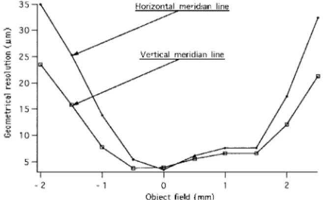
B. Theoretical resolution
In the image plane, spot diagrams of points regularly distributed in the object field were given by the ray tracing program. They can be assimilated to elliptic spots, the hori-zontal and vertical dimensions of which are H
8
and V8
. Theoretically, H8
must be constant when the object point moves on a vertical line; in the same way, V8
must be con-stant for a horizontal displacement. Those values are taken as the horizontal and vertical geometrical resolutions in the im-age plane; in the object plane, the corresponding resolutions, plotted in Fig. 8, are then:H5H
8
/GH and V5V8
/GV. ~10!We can see that in a field of about 2 mm in diameter, both resolutions are equal and lower than 7mm~we will call
FIG. 7. Adjustment of the microscope. An auxiliary mirror, M0,
perpen-dicular to the line AO1, is placed in front of the bimirrors and fixed on the
base plate that bears them. The useful rays can reach the bimirrors through the x-ray input hole which is centered on AO1. For adjusting the
micro-scope, in a laser or test chamber, we use a small diameter laser beam ('0.5 mm) that simulates the incident x-ray pencil. By tilting the micro-scope, we make M0perpendicular to that beam. By translating the
micro-scope, the beam is positioned on the center of the adjustment hole, materi-alized by a pinhole which gives concentric diffraction rings when the beam is well centered; two final translations of known values position it on the center of the input hole.
FIG. 8. Geometrical resolution vs object field. That resolution is calculated from the dimensions of spot diagrams given, on the image plane, by rays coming from different points on the horizontal or vertical meridian lines of the object plane; those dimensions are then divided by the corresponding magnifications. Resolution about 7mm is obtained within 2 mm field.
Fgthis resolution!. We call it the ‘‘best resolution’’ field and we can see that it is decentered with respect to the pseudo-axis by about 0.4 mm in both directions.
For low-energy x rays, the effect of the diffraction is not negligible. On the assumption that the geometrical aberra-tions are very low, the diffraction would limit the object resolution to Fd, which can be expressed by the classical relation
Fd51.22l/a, ~11!
whereais the aperture of the incident pencil which is sup-posedly conical. In our case,a52.13 mrad and the maximal value ofFd ~7.2mm! is reached for 100eV photons ~124 Å!. The length of the aperture mirrors, M2 and M4, was optimized4 for minimizing the global aberration resulting from the superposition of the diffraction and the geometrical aberration. In the 2 mm field previously defined,Fd is of the same order as Fg and we will assume that the global reso-lution is given by the following formula:
F5~Fd
21F
g
2!1/2. ~12!
Outside that field, we will keep the same formula and giveFgthe values H or V, which will lead to the estimated resolutions plotted in Fig. 9. For higher energies~.200 eV!,
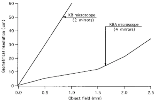
the diffraction can be considered as negligible. In Fig. 10, we compare the resolutions achieved by two or four mirror op-tics versus object field.
C. Tolerances
The accuracy of the radius of curvature measurement is about620 mm for a 100-mm-diam mirror. The four mirrors of the microscope are cut up in this mirror and we admit that, thanks to a certain number of previous precautions, their ra-dius is not modified by the process. Taking centering and edging accuracy into account, we took as limits620
9
for the angles and65mm for the essential sizes~for the other sizes we took 60.05 or 60.5 mm according to the case! of the steel parts. Then we calculated the effect of such variations on the size of the image spots. The most important param-eters were the angles and their variations led to a size in-crease of 8% to 9%, which is not negligible. We then had to take care of the tolerances on the other parameters.V. MAKING OF THE FOUR-MIRROR MICROSCOPE
The complexity of this optical system conducted us to choose the principle of a mounting without adjustment. The accuracy of the angular and lateral positioning is obtained by a perfect respect of tolerances for the optical and mechanical parts at each step of the fabrication process.
Figure 11 shows the drawing of the microscope; the cap-tion explains how the different parts are mounted on each other. Except for the x-ray mirrors which are made of silica and cemented on their bearers, all the other parts are made of steel and fastened together by screws; they are located one compared to another due to stops and wedges, some of the stops being used when sticking the mirrors on their bearers.
FIG. 9. Global object resolution at 100 eV~estimated!. That resolution takes into account the effects of diffraction for x rays of 100 eV energy. The incident pencil is supposed conical; the diffraction pattern is calculated by the classical formula and added quadratically to the geometrical resolution.
FIG. 10. Approximate comparison of the theoretical resolutions of KB and KBA microscopes.
FIG. 11. Drawing of the microscope. Keys:~1! the base plate; ~2! the two bearers of bimirror;~3! the assembling part of the two bimirrors; ~4! the four x-ray mirrors, M1– M4; ~5! the stops that are used as reference; ~6! the
adjustment mirror M0. The x-ray mirrors~4! are stuck two by two on the
bimirror bearers~2! in order to make the two bimirrors. On each bearer, the two mirrors are located by removable stops~5! which are also used when positioning the bimirrors on the assembling part ~3! on which they are screwed~a removable wedge is put under the second bimirror!. That part is then screwed on the base plate~1! which bears the adjustment mirror ~6!.
3417 Rev. Sci. Instrum., Vol. 68, No. 9, September 1997 X-ray microscope
The front mirror M0, which allows the microscope adjust-ment in the chamber, is also a steel part and its front is optically polished.
The x-ray mirrors which have the same radius of curva-ture are rectangular parallelepipeds cut up in a silica mirror of 100 mm in diameter. All their sides are optically polished; the side which will reflect the x rays is spherical and the tangent plane in its center is parallel to the opposite side with an accuracy much better than 20
9
. Their widths and thick-nesses are nearly the same ('1 cm); on the contrary, their lengths are very different as indicated in paragraph 4.1. Length and width tolerances are 60.05 mm but we have foreseen that the thickness might be adjusted with an accu-racy of 1mm with regard to the real measures of their bear-ers.VI. EXPERIMENTAL RESULTS
In Sec. III D, we examined the operating conditions of the microscope in a laser chamber due to the optical unit in which it is implemented. As the photon energy of the x rays reflected by the mirrors is low (,800 eV), they must propa-gate under vacuum. An isolating valve is fixed to the output side of the optical unit; the detector @film, charge-coupled device ~CCD!, camera,...# is connected to that valve by a 2-m-long tube equipped with vacuum pumps and gauges, which allows easy removal of the film after each exposure.
As the detector is generally sensitive to visible and UV radiations emitted by plasmas or even by the filament of classical x-ray sources, it is protected by a filter made of a thin mylar foil coated by 0.2 mm of aluminum; the spectral response of the microscope equipped with such a filter is displayed in Fig. 12. We can see that its best response is situated in the lower part of the x-ray range.
A. Tests with the Henke source
Before mounting the microscope on a laser chamber we wanted to test it on a cw x-ray source. For that purpose, we dispose of a Henke5 source. The optical unit is fixed to a small chamber that simulates a laser one; this chamber is joined to the source by a part in which are implemented the
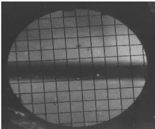
UV filter and the metallic grid which plays the part of a resolution pattern ~Fig. 13!. As the anode cannot be placed very close to the grid, we need an emitting zone a little larger than the object field; that is the case with the Henke source the emitting zone of which is about 14 mm high by 10 mm wide; moreover its brightness is roughly uniform except for a black narrow strip corresponding to the anode edge~Fig. 14!. The images were recorded on Kodak SB2 film. Although it is not very sensitive to low-energy x rays, it is very con-venient and more practical than special films. The source was operated at 12 kV with an electronic current of 100 mA and the time exposures were about 2 h each because of the very small amount of x-ray power available in the useful part of the spectrum. Figure 14 shows the image of a 25.4 mm grid ~the period of the grid is 25.4 mm in both directions! supported by a 70 mesh grid (period5363mm); its useful area is limited by a 4-mm-diam hole in its bearer. On the film we can see that the image of the fine grid is very good nearly all over the field. Figure 15 shows an enlargement of small zone of a 12.7mm grid image: the resolution is still good but
FIG. 12. Spectral response of the microscope associated with a filter (1.5mm mylar10.2mm Al). The curve was computed following the formu-las and data given by Henke in Ref. 5; it displays the absorption of the mylar foil due to carbon~K edge at 284 eV! and oxygen ~K edge at 532 eV!, added to the reflectivity lack of silica about 532 eV~oxygen!.
FIG. 13. Schematic arrangement for testing the microscope with the Henke source. The x-rays are emitted by the two front sides of the hexagonal anode; those surfaces are struck by electrons which follow semicircular trajectories from a filament placed behind the anode. So the atoms of tung-sten evaporated from the filament cannot directly reach the emitting zone which stay clean longer than in the classical sources. That zone is large enough~about 10314 mm! to backlight the metallic grid over the desired field~about 4 mm in diameter!.
FIG. 14. Image of a 25.4mm grid. That grid is supported by a 70 mesh grid
~363mm period! placed on a hole of 4 mm in diameter. We can see that the resolution is better than 25mm nearly all over the field. The black strip in the center is due to the lack of x rays from the anode edge.
it is limited to an area corresponding to an object field of 2 mm in diameter which is decentered by about 0.4 mm with respect to the center of the 4-mm-diam hole as it was ex-pected in Fig. 8. For lack of finer grids, we could not display the 5mm theoretical resolution in the field center.
The locations of grid and film with respect to the micro-scope were the theoretical ones. By varying the distance be-tween the 12.7mm grid and the microscope, we were at the best focus and variations of62 mm were necessary to see a loss of resolution at the edge of the 2 mm field.
FIG. 15. Image of a 12.7mm grid. This grid is mounted as the previous one. Here we see an enlargement corresponding to one mesh of the supporting grid. The resolution is good but the whole photograph shows that the field is limited to about 2 mm.
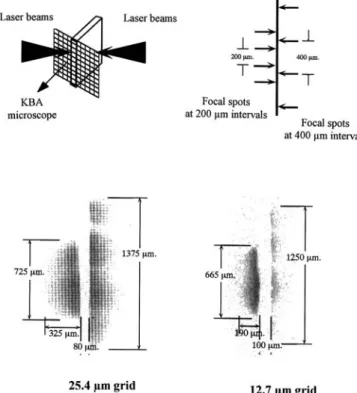
FIG. 16. Resolution tests with a laser plasma x-ray source. The eight laser beams of Octal facility are focused on the two sides of a gold foil, the width of which is about 100mm. The energy of each beam is about 40 J of 3v light~0.35mm! deposited in 1 ns on a 200mm spot~'1014W/cm2
irradi-ance!. A metallic grid stuck on the edge of that foil is backlighted by the x rays emitted by the four plasmas created on each side. On the left side, they are rather close to one another and they act as one source as it can be seen on the images of grids displayed under the target drawings; on the contrary, on the right side, they are far enough to be seen as separate sources. The grid images are reconstructed from the data obtained by digitizing the films.
FIG. 17. Exposure profile on the images displayed on the previous figure:~a! 25.4mm grid;~b! 12.7mm grid. In both cases, the contrast is good,~respectively 73% and 40%!.
3419 Rev. Sci. Instrum., Vol. 68, No. 9, September 1997 X-ray microscope
B. Tests on Octal–He´liotrope facility
Before using the instrument for studying laser plasmas, we checked its spatial resolution in He´liotrope target cham-ber. Two powerful x-ray sources were created by irradiating each side of a thick plane gold target with four beams of Octal laser; a fine grid was glued on the target extremity as shown in Fig. 16. The energy of each beam was about 40 J at the wavelength of 0.35 mm; the pulse duration being 1 ns, the irradiance was on the order of 1014W/cm2. In order to get a rather large source dimension, we spatially separated the focal spots of the beams in the direction parallel to the grid plane. The intervals were equal to 200mm on one side and 400mm on the other side of the target which gave source lengths on the order of 700 and 1300mm, respectively. The sources were located at 3 mm from the grid which was then backlighted and the KBA microscope gave the image of that grid onto a SB2 film. The protecting filter was made of 1.5 mm mylar coated with 2300 Å of Al. The target, the laser spot positions, and the results are presented in Fig. 16.
The images are reconstructed from the data obtained by digitizing the films. Figure 17 displays enlargements of those images and exposure profiles in the middle of a row of grid holes; for the 25.4mm grid, the contrast is about 73% and for the 12.7mm one, 40%. The resolution was then convenient to use the KBA microscope for studying any other laser plas-mas. Preliminary experiments have been conducted recently and their results will soon be published.
VII. DISCUSSION
We succeeded in building a grazing incidence x-ray mi-croscope with a high resolution within a large field: about
5–7mm within a 2-mm-diam field and better than 25–30mm within 4 mm diameter. Based on one hand on the use of spherical mirrors which may be quite well figured with a very low surface roughness and, on the other hand, on the use of accurate but currently work-finished steel parts, its building is relatively easy and its price is reasonable. Thanks to the low roughness of the mirrors, the scattered light is minimized and the images are well contrasted.
It constitutes an interesting device for laser plasma diag-nostics and will be very useful in future experiments con-ducted with more powerful lasers. For those experiments, it will be necessary to increase its spectral range towards harder x rays~1–10 keV!; that increase could be obtained by lowering the grazing angle~half a degree seems to be a prac-tical limit value! and coating the mirrors with either very dense metal ~gold or platinum! or multilayers.
ACKNOWLEDGMENTS
The authors would like to thank all the people and teams who helped us, especially the IOTA optical workshop which figured the mirrors and assembled the microscope.
1
P. Kirkpatrick and A. V. Baez, J. Opt. Soc. Am. 38, 766~1948!.
2F. Seward, J. Dent, M. Boyle, L. Koppel, T. Harper, P. Stoering, and A.
Toor, Rev. Sci. Instrum. 47, 464~1976!.
3J. Dyson, Proc. Phys. Soc. London, Sect. B 65, 580~1952!.
4R. H. Price and M. J. Boyle, LLNL Laser Program Annual Report 1978 ~UCRL-50021-78!, pp. 6.14–6.23.
5B. L. Henke and M. A. Tester, Advances in X-ray Analysis~Plenum, New