HAL Id: hal-01292076
https://hal-iogs.archives-ouvertes.fr/hal-01292076
Submitted on 16 Jan 2018
HAL is a multi-disciplinary open access
archive for the deposit and dissemination of
sci-entific research documents, whether they are
pub-lished or not. The documents may come from
teaching and research institutions in France or
abroad, or from public or private research centers.
L’archive ouverte pluridisciplinaire HAL, est
destinée au dépôt et à la diffusion de documents
scientifiques de niveau recherche, publiés ou non,
émanant des établissements d’enseignement et de
recherche français ou étrangers, des laboratoires
publics ou privés.
Coherent combination of ultrafast fiber amplifiers
Marc Hanna, Florent Guichard, Yoann Zaouter, Dimitrios Papadopoulos,
Frédéric Druon, Patrick Georges
To cite this version:
Marc Hanna, Florent Guichard, Yoann Zaouter, Dimitrios Papadopoulos, Frédéric Druon, et al..
Coherent combination of ultrafast fiber amplifiers. Journal of Physics B: Atomic and Molecular
Physics, Institute of Physics (IOP), 2016, 49 (6), pp.062004. �10.1088/0953-4075/49/6/062004�.
�hal-01292076�
Coherent combination of ultrafast
fiber
ampli
fiers
Marc Hanna
1, Florent Guichard
1,2, Yoann Zaouter
2,
Dimitris N Papadopoulos
3, Frédéric Druon
1and Patrick Georges
11
Laboratoire Charles Fabry, UMR 8501, Institut d’Optique, CNRS, Univ. Sud, Université Paris-Saclay, 2 Av. A. Fresnel, 91127 Palaiseau, France
2
Amplitude Systèmes, 11 avenue de Canteranne, Cité de la Photonique, 33600, Pessac, France
3Laboratoire d’Utilisation des Lasers Intenses, Ecole Polytechnique, CNRS, CEA, UPMC, Route de
Saclay, 91128 Palaiseau, France E-mail:[email protected]
Abstract
We review recent progress in coherent combining of femtosecond pulses amplified in optical fibers as a way to scale the peak and average power of ultrafast sources. Different methods of achieving coherent pulse addition in space(beam combining) and time (divided pulse
amplification) domains are described. These architectures can be widely classified into active methods, where the relative phases between pulses are subject to a servomechanism, and passive methods, where phase matching is inherent to the geometry. Other experiments that combine pulses with different spectral contents, pulses that have been nonlinearly broadened or successive pulses from a mode-locked laser oscillator, are then presented. All these techniques allow access to unprecedented parameter range forfiber ultrafast sources.
Keywords: coherent combining, ultrafast optics,fiber amplifiers
1. Introduction
Fiber amplifiers have become a major technology in the high average power laser sources landscape (Richardson et al 2010). They combine numerous advantages making
them ideally suited for an increasing number of applications, including industrial material processing, medical treatment and scientific experiments. The double clad geometry allows pumping with high power laser diode systems, and provides excellent power transfer efficiency from the pump to the single transverse mode output beam, determined by the waveguide properties of the fiber core. Ytterbium-doped fibers exhibit a very low quantum defect from the pump at 976 nm to the signal around 1030 nm, yielding high optical-to-optical efficiency and low heat deposition in the gain medium. The large surface to volume ratio of thefiber, related to its geometrical shape, facilitates heat dissipation. These
unique properties have allowed the design of multi-kW continuous wave(CW) diffraction-limited fiber laser sources. When used to amplify femtosecond pulses, at large peak power levels, the peculiar geometry of fiber amplifiers turns into a disadvantage in terms of allowable pulse energy when compared to other gain medium shapes. The optical mode is strongly confined within the fiber core, and guided over meter-sized lengths, enhancing nonlinear interaction with the fiber material. Effects such as self-phase modulation (SPM), self-focusing, optical damage at the facets, appear at modest pulse energy levels compared to typical bulk amplifiers. Moreover, the limited gain bandwidth of ytterbium-doped glass, combined with typical large gain levels, induce gain narrowing and limit the achievable amplified pulsewidth to 300–500 fs.
To overcome these drawbacks of ultrafast fiber ampli-fiers, the main idea is to reduce the optical intensity inside the fiber core by distributing the power over time and space.
Chirped-pulse amplification (CPA) consists in introducing a large amount of group-velocity dispersion (GVD) to stretch the input pulse in time by a large ratio, thereby decreasing the peak power by the same ratio(Strickland and Mourou1985).
At the output of the amplifier, pulses are compressed down to their initial duration by introducing the opposite GVD. The stretched pulse duration is limited to a few nanoseconds by the size and cost of optical gratings that are used in stretchers and compressors. In space, specific quasi-singlemode fibers with large mode area have been designed and fabricated to reduce nonlinear effects along amplification (Stutzki et al 2014). Scaling of the mode area is limited by the
appearance of higher order guided modes that decrease the output beam quality and the temporal contrast of the pulses. For Ytterbium-dopedfibers, the current maximum achievable mode-field diameter is about 100 μm. These techniques have been developed over the last twenty years, allowing the generation of mJ femtosecond pulses (Eidam et al 2011).
However,fibers that are used to reach these energy levels are very large mode area rodtypefibers in which thermo-optical effects limit the average power to around 100 W.
To further scale the peak and average power of femto-secondfiber amplifiers, it is a natural idea to extend the dis-tribution of power to several beams in space and pulses in the time domain, leading to the concept of coherent combining. Coherent beam combining has beenfirst implemented for CW lasers(Fan2005), before being extended to the pulsed regime
for nanosecond (Cheung et al 2008a, Lombard et al 2011)
and femtosecond pulses. The main idea is to split an initial pulse to be amplified in several replicas either in multiple beams (coherent beam combining) or at multiple delays (divided pulse architecture), proceed to amplification, then combine them by controlling the relative optical phase between all replicas. Most of the experiments in thefield have been performed withfiber amplifiers because of their potential for integration and high average power operation, and because beam quality is an essential feature to be able to efficiently combine several beams. First demonstrations appeared in 2010–2011 (Seise et al 2010, Daniault et al2011a), showing active beam combining of two
femto-secondfiber amplifiers. Since then, a large number of archi-tectures involving active or passive phase stabilization in the space and time domains have been proposed and demon-strated. These concepts have already allowed establishing new record performances for fiber amplifiers, with multi-mJ sources emitting an average power of several hundred watts (Klenke et al2014a).
In this review, we review the concepts that have been introduced over the last few years, from general notions to the description of specific laser source architectures. The dis-cussion is extended outside the scope offiber amplifiers to describe the use of the same femtosecond coherent combining techniques to scale pulse energy in nonlinear temporal post-compression waveguide setups, demonstrating the use of these concepts for pulse durations down to the few-cycle regime. Femtosecond resonant passive enhancement cavities are then described as a different type of coherent combining strategy. To conclude, large scale femtosecond laser facility
proposals based on coherent combining are shortly described. Indeed, coherent combining techniques constitute a very promising path towards future high energy, high repetition rate ultrafast sources for applications such as particle accel-eration, and high power secondary sources of extreme ultra-violet radiation and x-rays.
2. General notions
We first describe general aspects of femtosecond coherent combining systems. After exposing the basic principle, var-ious implementations of splitting and combining setups are considered. Phase noise properties offiber amplifiers are then introduced, and various techniques used to lock the optical phase of several pulses are explained. Finally, the most common performance metric of a coherent combining system, denoted as combining efficiency, is presented.
2.1. Coherent addition of short pulse electric fields
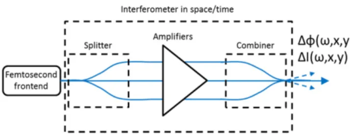
Experimental setups used to perform coherent combination of femtosecond pulses can all be seen as optical interferometers that include amplifiers in the multiple possible paths, as depicted infigure1. An initial femtosecond frontend is used to generate the optical pulses to be amplified. These pulses are subsequently split and sent in the interferometer arms, amplified, and recombined in a single output pulse. The efficiency of the system is related to the ability to control the phase accumulated by optical pulses in each path in order to guarantee constructive interference on one of the inter-ferometer outputs. This constructive interference condition must be satisfied over both the space/wavevector (Goodno et al 2010) and time/spectral domains (Klenke et al 2011, Hanna et al 2013). In practice, and given the fact that most
coherent combining setups are optimized to combine identical beams and pulses, this condition implies that the beams to be combined should exhibit the same spatial profile and wave-front, together with the same spectral content and spectral phase. The latter condition is specific to ultrafast coherent combining systems, and can be seen intuitively in the time domain: in addition to the phase matching condition of optical carriers, the pulses to be combined must arrive on the com-bining element at the same time or group delay, which is determined by thefirst-order Taylor expansion of the optical phase with respect to angular frequency. Higher order terms in this expansion determine the temporal profile of the pulses,
and must also be matched. Possible optical phase mismatch of the beam/pulses to be combined translates into a decrease of the combining efficiency, and therefore leads to significant power loss into unused output ports of the interferometer and/ or decrease of the combined peak power as detailed in section2.5.
2.2. Splitters and combiners in space and time
Fabrication of the amplifying interferometer necessitates the use of optical components to perform the dividing and com-bining functions. Dividing and comcom-bining can in principle be done using the same components, but can differ in practice due to various considerations, in particular power handling: the combiner is a critical component that must be able to withstand thefinal average power and peak intensity without introducing losses.
Coherent beam combining geometries can be classified in two broad categories, denoted as filled aperture and tiled aperture, as illustrated in figure2. In the tiled aperture geo-metry, the beams to be combined are simply positioned next to one another in the near field. Coherent combining is effective only in the far field, where a single spatial lobe is synthesized if the optical phase of the sub-beams is con-trolled. In this case, the combiner element can be either a simple lens or even just the diffraction over a certain distance. This simplicity makes the tiled aperture architecture attractive when the number of beams to be combined is large, or when power handling issues are important. The spatial properties of the combined beam depend on the precise geometrical arrangement. In particular, thefilling factor of the composite beam determines the fraction of power contained in the cen-tral combined lobe. The combined beam properties also depend on the phase relationship between sub-beams. If a large number of beams are combined, control of this phase relationship could enable the control of the combined beam, for instance beam steering capabilities. In the framework of femtosecond beam combining systems, only one experiment reports the use of the tiled aperture geometry to our knowl-edge (Ramirez et al 2015). This experiment highlights one
characteristic of the tiled aperture geometry for ultrafast pulses that was previously theoretically identified (Hanna et al2013): residual group velocity mismatch between
sub-beams are translated to spatio-temporal couplings in the output beam.
The filled aperture approach is closer to the idea of the interferometer, since the beams corresponding to each inter-ferometer path are superposed onto a combining element to generate a single output beam. In this case, and if coherent addition is achieved ideally, the spatial properties of the output beam are the same as each individual beam before combination. Almost all femtosecond beam combining experiments use this approach, because the number of com-bined beams is less than 10 in most cases, and because the generated output beam generally exhibits better spatial qual-ity. The simplest way to divide/combine beams in this case is to use a two-port component such as beamsplitters(Daniault et al 2011a) or polarizing beamsplitters (Seise et al 2010).
Cascading such binary components allows in principle the generation and combination of an arbitrary number of beams, although component losses are accumulated in the process.
To combine a large number of beams with a single component using thefilled aperture combining geometry, dif-fractive optical elements(DOE) have been used in CW com-bining experiments(Cheung et al2008b). A DOE is essentially
a phase grating that is optimized to split an incident beam into N output beams with a large efficiency and roughly equal power in each beam. The relative phase relationship of the N output beams is deterministic andfixed by grating design. Due to the reciprocal nature of light propagation, this component can also be used backwards: if N beams are incident on the DOE with angles that correspond to optimized diffraction orders, and if their phase relationship matches the DOE design, the output power is mostly carried by a single beam. DOEs have been demonstrated both in one dimensional (Redmond et al2012) and two dimensional designs (Thielen et al2012),
with large efficiencies and at high power (kW) level. In the femtosecond regime, the large optical bandwidth of pulses to be combined can become incompatible with the use of DOEs: like any grating, DOEs introduce angular dispersion, leading to a recombined beam that carries angular chirp. This effect, together with the modest number of combined beams in reported work, has prevented an experimental demonstration of the use of DOEs in a femtosecond beam combining experi-ment. However, depending on the optical bandwidth and the DOE design, this effect can be negligible. Optical
arrangements have also been proposed to reduce this effect (Zapata-Rodríguez and Caballero2007), and it can also be
pre-or post-compensated using arrangements of complementary angularly dispersive components.
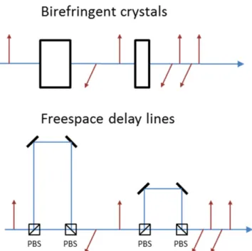
Splitter and combiner subsystems are also needed to generate several replicas of an initial pulse in the time domain. They use the polarization state of the light to route replicas of the pulse through the time domain interferometer. For values of group delay between replicas up to a few tens of picoseconds, crystals that exhibit a large group birefringence can be used to separate the ordinary and extraordinary com-ponents of incident light, as shown in figure 3 (Zhou
et al 2007). Such crystals include yttrium vanadate (Kong
et al2012) and calcite (Jacqmin et al2015). These
compo-nents allow an inline interferometer configuration. When larger delays are required, for example to separate pulses that are stretched to nanosecond durations in CPA amplifiers, freespace delay lines (Zaouter et al 2013) can be used in
conjunction with polarizers to fabricate unbalanced Mach-Zehnder interferometer that are equivalent to birefringent crystals, as shown infigure3. In this case, a careful and stable alignment of the interferometer must be done to guarantee a single beam at the output. Both implementations can be used to split and/or to combine pulses in time.
2.3. Phase noise in fiber amplifiers
In beam combining experiments, since a single femtosecond oscillator is used to seed severalfiber amplifiers, phase fluc-tuations between beams to be combined originate solely from fiber amplifiers. It is therefore important to measure and ana-lyze phase noise introduced by such amplifiers, for instance to determine the characteristics of the feedback loop in terms of
bandwidth and gain in active beam combining systems. Such studies were carried out in the frame of CW coherent com-bining (Augst et al 2004) by performing self-heterodyning
experiments between a reference beam and a fiber amplified beam. These experiments show that phase fluctuations are dominated by environmental thermal and acoustic contribu-tions, and become negligible beyond 10 kHz. More speci fi-cally, there is typically a large and monotonic change of the optical phase over several thousand waves at amplifier turn-on, corresponding to heat up time. During this time, the group delay also continuously drifts over several hundred femtose-conds. Once the thermal steady-state is reached, the optical phase varies over a typical scale ofπ/10 on a millisecond time scale. Over longer time intervals of tens of seconds, the relative phase excursion varies over a typical range of tens of radians that can be reduced to a few radians by carefully isolating the systems acoustically. These numbers correspond to laboratory environments, and since the origin of the noise is mostly thermal and acoustic, they can vastly differ depending on experimental conditions. Feedback loops that control the rela-tive phase between amplifiers usually feature bandwidths ran-ging from 100 Hz to 10 kHz, allowing the use of various phase actuators such as piezo-mounted mirrors, electro-optic inte-grated phase modulators, and spatial light modulators.
Because of the mostly environmental nature of the phase noise, it is expected that integrating the multiple fiber amplifiers into a single structure through the use of a multi-core fiber should drastically reduce phase fluctuations between beams to be combined. This was verified in various multicore amplifier experiments (Hartl et al 2009), and a
recently reported work shows active combining in the fem-tosecond regime with a decoupled 7-corefiber using a feed-back bandwidth of only 2 Hz(Ramirez et al2015).
For ultrafast combining experiments, the group delay introduced by each amplifier and higher orders of the spectral phase could in principle also fluctuate in time. However, in reported femtosecond experiments, only a static manual adjustment of the relative group delay is performed, and the systems do not exhibit large fluctuations of delay between interferometer arms once the thermal steady state is reached. It is expected that combining systems should be increasingly sensitive to suchfluctuations when the pulses to be combined are shorter, or equivalently the optical bandwidth larger. In this case, a group delay locking mechanism, as demonstrated in (Weiss et al 2012), might be implemented. It simply
consists in achieving simultaneous phase locking at two well separated wavelength components, thereby reducing the spectral phase slope, i. e. the group delay, to zero.
2.4. Phase measurement and active feedback techniques
Active beam combining of femtosecond fiber amplifiers requires real-time feedback on the relative optical phase between beams. This feedback is based on the detection of one or several control signals from the output of the system. Phase control systems can be broadly classified in two cate-gories: phase control is either based on a deterministic mea-surement of relative phases between beams, or on stochastic
Figure 3.Splitters and combiners in the time domain. The red arrows represent the polarization state of successive pulses. Waveplates have been omitted. PBS: polarizing beam splitters.
hill-climbing algorithms that seek to maximize a metric of the system performance.
Among systems based on phase measurement, several techniques have been implemented and can be used for ultrafast fiber amplifiers. Frequency tagging, or LOCSET (locking of optical coherence via single-detector electronic-frequency tagging) (Shay et al2007), consists in introducing
a small-amplitude phase modulation on each beam at a pre-determined frequency. Heterodyne detection of this signal with either a reference signal or an unmodulated beam (denoted as self-referenced LOCSET), followed by lock-in amplification, allow identifying and measuring the relative optical phase of each beam with a single detector at the output of the system. These phases are then used as error signals by the feedback system to generate control signals applied on phase actuators located in each interferometer arm. The nonzero amplitude of phase dithers induces a residual phase error that has in most practical case negligible impact on the combining efficiency. In CW regime LOCSET can be easily scaled to a large number of channels and has been used to combine 32 low-power CW laser beams(Flores et al2013).
In pulsed regime, the applied phase dither frequency must be less than half the repetition rate of the system. For high energy systems, repetition rates can be in the range 10 kHz– 1 MHz, and scaling the number of channels is the result of a tradeoff between number of channels and feedback band-width. Due to its simplicity of use and efficiency, frequency tagging has been used in several femtosecondfiber amplifiers combining experiments (Siiman et al 2012, Daniault et al2011a, Kienel et al2015).
For coherent combining systems that use two-port polarizing beam splitters as combining components, measur-ing the relative phase between beams is equivalent to mea-suring the output polarization state. In this case, the method introduced by Hänsch and Couillaud (Hänsch and Couil-laud1980) can be used to generate an error signal that allows
phase locking. This technique requires the use of N-1 detec-tors, where N is the number of beams to be combined. It has been implemented in femtosecond systems(Seise et al2010).
In the case of tiled aperture systems, optical phase measurement can also be done in space by measuring the position of interference fringes between beams to be com-bined or with respect to a reference beam. In particular, lateral
shearing interferometry can be used to measure relative phases with a single camera for a large number of channels and with kHz bandwidths(Bourderionnet et al 2011).
The second broad category of phase control system used in the frame of coherent combining is based on algorithms that aim at maximizing a metric of the system performance (often the output power or on-axis intensity) without the knowledge of phase errors. A widely used algorithm, first applied in the context of adaptive optics for astronomy, is stochastic parallel gradient descent (SPGD) (Vorontsov and Sivokon 1998). This algorithm works by applying small
random phase perturbations to the current state of the system, and examining the effect of the perturbation on the perfor-mance metric. From this observation, a control signal is generated that increases the metric, and the algorithm con-verges to a zero gradient point where the metric is maximized. Unlike deterministic phase control systems, the convergence time of SPGD feedback increases linearly with the number of channels, or the equivalent servo bandwidth decreases like 1/N. Convergence time can be kept low enough by increasing the iteration rate, requiring larger computing power and actuator/detector bandwidth and lower latency. This draw-back balances the main advantage of SPGD, which is the very simple detection scheme.
2.5. Combining efficiency
To quantify the performance of a specific coherent combining system, a single number denoted as combining efficiency is often used. Depending on the precise situation, this number can encompass different things. The most usual definition is in terms of average power in afilled aperture system, where the combinedfield at the output is simply the coherent sum of electric fields Enemitted by each path of the interferometer
system. Assuming N combined beams and an ideal combin-ing system designed for equal power in each arm, the com-bined average power Pcombcan be written as
P N E 1 . 1 n n comb 2 ( )
å
=Global differences in intensities and phase mismatches among electricfields to be combined decrease the combining
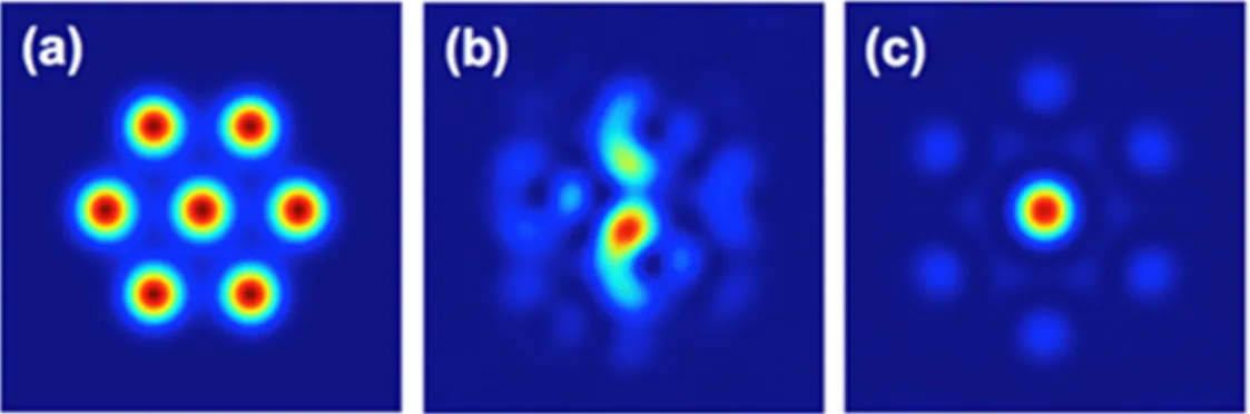
Figure 4.Example of a tiled aperture system obtained with numerical simulations.(a) Tiled beam in hexagonal arrangement. (b) Combined beam in the case of random phases for the sub-apertures.(c) Ideal combined beam. Adapted from (Ramirez et al2015).
efficiency. These differences can also depend on the space variables x and y (beam profile and spatial wavefront mis-match), and on time or frequency variables t and ω (spectral intensity or spectral phase mismatch, or equivalently temporal intensity and temporal phase mismatch). The combining efficiency is defined as the ratio of this combined power to the total average power emitted by the system:
P E . 2 n n comb 2 | | ( )
å
h =The impact of various intensity and phase defaults on combining efficiency has been studied both in the space (Goodno et al 2010) and time (Klenke et al 2011, Daniault et al2012a) domains. As expected from basic interferometry,
the combining efficiency is much more sensitive to phase variations than it is to intensity discrepancies among pulses to be combined. In experimental demonstrations, reported combining efficiencies are usually in the range 80%–95%, depending on the number of combined channels, and non-linearity level at whichfiber amplifiers are operated.
The nonlinearity level of afiber amplifier is conveniently described by the B-integral defined as:
B P z dz, 3 L 0 peak( ) ( )
ò
g =where z is the longitudinal coordinate, L is thefiber length, Ppeak is the peak power in the fiber, and γ is the nonlinear
coefficient given by n .
cA
2 0 eff
g = w In this expression, n2 is the
nonlinear index of the medium, ω0 is the optical angular
frequency, c is the speed of light in vacuum, and Aeffis the
effective area of thefiber. The B-integral corresponds to the maximum nonlinear phase shift accumulated through SPM inside thefiber. An amplifier is often considered as operating in nonlinear regime if B>π. Most high-energy femtosecond fiber amplifiers operate above this limit, with a B-integral that can reach 10 rad.
The most significant effect of SPM in coherent combin-ing systems is that it translates fluctuations of power into fluctuations of phase, which in turn hinder the combining process. Quantitative analyses of the impact of nonlinearity on the combining efficiency have been carried out in the frame of CPA systems both with analytical approaches (Klenke et al 2011) and Monte-Carlo simulations (Hanna
et al2013). These analyses also include the impact of
diff-erential group delay and group velocity dispersion on the performance metric. When coherent combining is used to scale nonlinear compression setups, the nominal B-integral level can be higher (10–20 rad), and input pulses are unchirped, leading to much more pronounced spectral profile changes. A numerical analysis of the impact of nonlinearity on the combining efficiency in this case is reported in (Gui-chard et al2014).
Thermo-optic effects arising at high average power also make efficient coherent combining more difficult, because they usually lead to optical aberrations (spatial amplitude and/or phase distortions) that must be matched on the beams
to be combined. For pulsed systems that primarily aim at scaling the output peak power, a variation of the definition given by equation (2) can be used, where peak powers are
used to define the efficiency (Hanna et al2013).
Modifications can be made to the simple definition of combining efficiency to take into account the added com-plexity of some combining geometries. For instance, in tiled aperture geometry, relative phases have an impact on the output beam shape, and thefilling factor leads to a beam that exhibits side lobes, as shown in figure4. In this case, it is more difficult to define what constitutes the useable output beam, and reported accounts of such experiments tend to use the power contained in the central lobe as a measure of combined power. Similarly, in temporal pulse combining architectures, imperfect phase matching between inter-ferometer paths can lead to satellite pulses in the time domain on the recombined pulse, at delay values that correspond to the dividing and recombining subsystems. In this case, the useable part of the output power must be restricted to the main temporal pulse, and a temporal combining efficiency is con-sidered in addition to the beam combining efficiency.
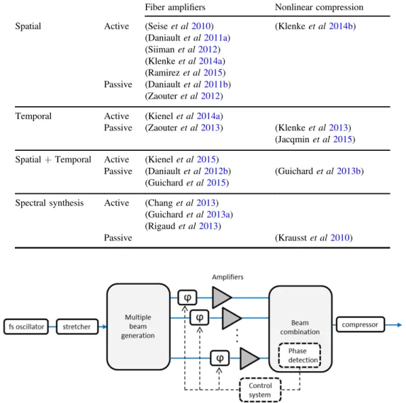
3. Architectures and experimental implementations We now focus on the description of the variety of archi-tectures that have been demonstrated in the past few years to perform coherent combining of femtosecondfiber amplifiers. Table 1 provides a non-exhaustive overview of references corresponding to experimental demonstrations detailed in this section. It also includes references corresponding to nonlinear compression setups detailed in section4.1.
3.1. Spatial: coherent beam combining
First experimental demonstrations of coherent combining with femtosecondfiber amplifiers have used the active beam combining geometry depicted in figure 5. In these experi-ments, pulses emitted by a single femtosecond oscillator are stretched, and the initial beam is separated in N beams that are amplified in parallel in N amplifiers. Since these amplifiers introduce phase noise, an active detection/feedback/actuator system controls and stabilizes the phase relationship between arms of the interferometer, using either frequency tagging, or the Hänsch-Couillaud detection. Phase feedback is achieved using piezo-mounted mirrors or electro-optics phase mod-ulators. Early demonstrations used two arms in a Mach-Zehnder geometry (Seise et al 2010, Daniault et al 2011a, 2011b), and this number was later extended to
four arms(Siiman et al2012). By using large stretching ratios
of several nanoseconds, very large mode area rodtypefibers, together with a four beam combining system, impressive performance were demonstrated, with sources delivering both large average and peak powers: 500 W, 1.8 GW (Klenke et al 2013), 230 W, 22 GW (Klenke et al 2014a, 2014b).
Active coherent beam combining allows scaling the global performances of a single amplifier (average and peak power) by a factor N, assuming perfect combining efficiency.
A key factor in these experiments is the ability to repli-cate accurately each arm and design the system so that upon recombination, the temporal/spectral and spatial properties of the amplified beams are as identical as possible. The guiding nature of the gain medium is particularly helpful in this sense, as it guarantees the beam quality, largely independent on operating power. In the time domain, some care is required to balance the amount of group-velocity dispersion introduced by each arm, and a tunable delay line is usually included in each arm to fine-tune the group delay. In highly nonlinear systems (B>π rad), the amount of accumulated nonlinear phase should also be matched to maximize combining ef fi-ciency(Daniault et al2012a,2012b). It is worthwhile to point
out that the polarization state at the output of amplifiers must also befixed, which can be guaranteed by the use of polar-ization-maintainingfibers. The combining efficiency in these experiments, that all usefilled aperture combining using two port optical components, depends on the number of arms combined, the level of nonlinearity and the average power, but generally lies in the 80%–95% range. The bandwidth of the electronic feedback systems in these demonstrations is of
the order of 1 kHz, sufficient to effectively suppress acoustic and thermal noise in a laboratory environment.
A recent proof-of-principle experiment (Ramirez et al 2015) using the same active beam combining
archi-tecture differs from previous works in several points. It integrates thefiber amplifiers in a single structure by using a multicorefiber that can be cladding-pumped by a single high power diode laser system. The main advantage is that relative phasefluctuations between beams to be combined are much reduced since the cores are very close to one another. This has been experimentally characterized, showing that it is suf fi-cient to correct long term phase drifts with a bandwidth of 2 Hz to phase lock the system. The second difference is that combining is performed using the tiled aperture geometry using a microlens array that collimates the seven output beams from the multicore fiber. The tiling geometry, and in particular the filling factor, limits the theoretical combining efficiency to 76% in this case, and the experimentally obtained efficiency is 50%. The difficulty in controlling the relative group delay in long and twisted multicorefibers calls for the use of straight and short rodtype multicorefibers such
Table 1.Overview of bibliographic references describing various architectures to perform coherent combining of femtosecondfiber amplifiers and nonlinear compression setups.
Fiber amplifiers Nonlinear compression Spatial Active (Seise et al2010) (Klenke et al2014b)
(Daniault et al2011a) (Siiman et al2012) (Klenke et al2014a) (Ramirez et al2015) Passive (Daniault et al2011b) (Zaouter et al2012)
Temporal Active (Kienel et al2014a)
Passive (Zaouter et al2013) (Klenke et al2013)
(Jacqmin et al2015)
Spatial+Temporal Active (Kienel et al2015)
Passive (Daniault et al2012b) (Guichard et al2013b)
(Guichard et al2015)
Spectral synthesis Active (Chang et al2013)
(Guichard et al2013a)
(Rigaud et al2013)
Passive (Krausst et al2010)
as those used in(Otto et al2014), that could be a promising
way to efficiently integrate femtosecond fiber coherent beam combining systems.
As an alternative to active coherent beam combining, passive architectures, implying that phase stabilization is an inherent characteristic of the system, have been proposed and demonstrated in the context offiber femtosecond amplifiers. The combination of two amplified beams is accomplished without the need for an active detection/feedback mech-anism. The principle of operation is to use an amplifying interferometer in which all arms are composed of the same overall optical path, the only difference between arms being the order in which each path element is encountered. This guarantees that, upon combination, spectral phases are mat-ched to all orders. The most obvious example of such an interferometer, and the only one that has been experimentally implemented to date, is the Sagnac interferometer, shown in figure6. This idea was proposed 20 years ago in the context of excimer amplifiers in the CW regime (Szatmari and Simon 1993). In this geometry, the splitter/combiner
laun-ches the two beams in a counterpropagating fashion in the Sagnac loop that includes one or severalfiber amplifiers. The symmetry of both paths is an important point to guarantee a high value of the combining efficiency (Daniault et al2011b).
These setups are intrinsically immune to phase noise fre-quency components below the inverse roundtrip time in the interferometer, corresponding to tens of MHz in meter-sized setups. This property has ensured robust phase locking of femtosecond beams in different contexts, e.g. allowing the generation of 600μJ, 300 fs pulses at 60 W average power level in a compact setup(Zaouter et al2012).
As detailed in(Hanna et al2013), it is possible to devise
interferometer arrangements to extend this principle to com-bine more beams and amplifiers. However, this is of limited interest in the case offiber amplifiers, since each beam must propagate through each amplifier, accumulating nonlinearity, which is precisely the phenomenon that limits the achievable performances. However, this could be an interesting per-spective in other systems such as bulk media-based multipass amplifiers, especially when limited by low gain and energy extraction capacity, asfirst demonstrated in reference (Papa-dopoulos et al2015).
3.2. Temporal: divided pulse amplification
Divided pulse amplification (DPA) consists in creating sev-eral replicas of an incoming pulse in the time domain, amplify the sequence of pulses, and recombine them coherently, as depicted infigure7. Note that in this configuration, a single beam is used throughout the system. DPA can therefore not be considered as a way to scale the average power of a given system. This process reduces the peak power by a factor equal to the number of replicas. Since it consists in distributing the power over time, it can be also seen as a discrete version of CPA. DPA hasfirst been proposed in the context of picose-condfiber amplifiers (Zhou et al 2007), where CPA is
diffi-cult to use because of the narrow optical bandwidth available. One implementation of DPA uses the same optical sub-system to perform both pulse division and combining, as shown infigure7. This allows automatic balance of the time interferometer, with pulses experiencing complementary delays on the way forward and back into the pulse division system. This feature bears resemblance with the Sagnac passive beam combining system described above. Passive DPA has been implemented in a variety of contexts, including picosecond fiber amplifiers (Kong et al 2012), stretcher
free ‘parabolic’ fiber femtosecond amplifiers (Daniault et al
2012b), and femtosecond fiber CPAs (Zaouter et al2013). In
the two first examples, birefringent crystals were used to divide and recombine the pulses, because the pulse duration was below a few picoseconds. The largest demonstrated number of replicas generated with crystals is 32. In the case of CPA, freespace delay lines were implemented to accom-modate the stretched pulse duration of several hundred picoseconds. An experiment using passive DPA and CPA has allowed the generation of 430μJ pulses from a rodtype fiber amplifier (Zaouter et al2013). In all cases DPA has allowed
peak power scaling by reducing the level of optical non-linearity and/or increasing the damage threshold in terms of pulse energy.
Limitations of the DPA architecture are related with the fact that successive pulses in the train might not experience the exact same condition upon propagation in the amplifier. For example, at high nonlinearity level (B>π rad), small deviations in intensity of the generated replicas can translate into phase shifts through SPM, hindering the temporal com-bining process, and the systems becomes more sensitive to any imperfection(Guichard et al2014). Another unavoidable
limiting effect is gain saturation in the fiber amplifying medium(Kienel et al2013). When the pulse energy becomes
of the order of the amplifier saturation energy, the gain experienced by successive replicas decreases, leading to ferences in intensity that can also be turned into phase dif-ferences through SPM or Kramers-Krönig induced index change. The train of amplified pulses that propagates through the combiner is therefore non-uniform both in intensity and phase, and combining efficiency decreases. In passive sys-tems, this saturation effect can be compensated in the case of only two temporal replicas by adjusting the intensity level between replicas at the input. For a larger number of replicas, the compensation is only partial: there are not enough
Figure 6.Sagnac amplifier configuration for passive beam
experimental degrees of freedom to adjust the amplitude of each replica, since the same subsystem is used to split and combine, and the number of replicas increases exponentially with the number of delay lines used. Implementations of passive DPA setups including optical components(such as a Pockels cell) allowing intensity control of each pulse can be imagined, but have not been demonstrated to our knowledge. To circumvent this problem, another implementation of DPA using separate divider and combiner subsystems was proposed, as shown in figure8. If the splitter and combiner are based on bulk birefringent crystals, phase differences between the ordinary and extraordinary polarization states induced by such crystals in a well-controlled environment are stable enough to implement the system without active phase control among pulse replicas. However, to use this scheme in conjunction with CPA, freespace delay lines are used both to divide and combine, making the system equivalent to a freespace Mach-Zehnder with meter-sized arm lengths. In this case, active phase control using techniques such as frequency tagging is required. Kienel et al 2014a reports on the gen-eration of 1.25 mJ femtosecond pulses using four replicas, a stretched pulse duration of 2 ns, and a rodtype fiber with a mode-field diameter of 75 μm. Although active DPA increa-ses the number of useable replicas even in the case of strong gain saturation, the number of degrees of freedom on the intensity of the input pulse train must be equal to N-1, where N is the total number of replicas. Pulse train shaping methods allowing the control of the intensity of each pulse are needed to scale this idea to a large number of replicas.
3.3. Spatial and temporal/active and passive
Looking at both previous sections, it has been a tempting idea to use simultaneously spatial and temporal approaches in order to further scale the number of replicas that can be amplified and combined. This leads to ‘spatio-temporal’ or
‘multi-dimensional’ coherent combining approaches. Since DPA dividing and combining subsystems generate a single output beam, reported demonstrations first implement tem-poral replicas generation before splitting each temtem-poral replica in several beams. After amplification, beams are first combined in space, and then temporal replicas are re-syn-chronized to generate a single output pulse. In these experi-ments, special attention must be paid to take into account the fact that the polarization state somehow encodes the temporal replica. In standard DPA systems, the amplifying medium must not exhibit polarization-dependent properties such as birefringence (polarization-maintaining properties) or polar-ization-dependent gain or loss. Indeed, these properties introduce differences in behaviors among replicas that prevent proper combination. An advantage of implementing both DPA and beam combining is that it makes the architectures compatible with polarization maintaining fiber amplifier or fibers exhibiting polarization-dependent gain and loss: tem-poral replicas have orthogonal polarization states that can be separated in two beams by a polarizer oriented at 45°, thereby generating two beams with a single linear polarization state that can be sent into PM fiber amplifiers. Spatio-temporal combining has been demonstrated both in fully passive and fully active architectures.
The passive approach consists in combining a Sagnac interferometer with a passive DPA setup. Since both approaches are limited in current practical setups to two replicas, it is a simple way to conceive an entirely passive coherent combining system that is compatible with high-energy fiber femtosecond amplifiers and uses 4 replicas. A recent demonstration (Guichard et al 2015) implements this
idea in a CPA system, using freespace delay lines to generate the temporal replicas, with a Sagnac interferometer including two 0.8 m-long rodtypefiber amplifiers. The setup allows the generation of 1.1 mJ 300 fs pulses with a combining ef fi-ciency of 90%, illustrating the relevance of the passive
Figure 7.Passive divided-pulse amplification.
architecture: the energy is scaled by a factor of four compared to performances achieved without any combining strategies, without the need for any active opto-electronic feedback loop system.
The active approach, on the other hand, consists in implementing an active DPA setup together with active coherent beam combining. A recent experiment (Kienel et al 2015) demonstrates the concept with four temporal
replicas and 2 amplifying arms forming a Mach-Zehnder interferometer, therefore using 8 overall replicas. Three active phase control systems are necessary to perform coherent combining, 2 for the temporal and 1 for the spatial multi-plexing dimensions. The active phase control system in this case uses the LOCSET method. Achieved combining ef fi-ciencies are between 75% and 95%, depending on the operation regime: 75% efficiency is obtained only for extreme parameters in terms of B-integral and/or energy compared to the saturation energy of the amplifiers. The added complexity of the setup compared to the passive approach is balanced by straightforward scaling capabilities of the technique in the spatial dimension.
Finally, the potential of combination of the active and passive techniques in the same setup seems to be an appealing perspective. In fact, the simplicity and the inherent robustness of passive combination setups could allow their use as the unit element integrated in an active combination configuration where two or more of these passively combined systems could be actively coherently combined, further scaling the so far obtained performance based on each approach separately.
3.4. Spectral: pulse synthesis
This section is devoted to the description of experiments that perform coherent addition of ultrafast opticalfields that have different optical spectra. It deviates from previous sections in the sense that the combined pulse is not a scaled version of supposedly identical lower energy pulse replicas, since its spectral content is broader than that of individual pulses. However, this concept, sometimes denoted as spectral coherent combining or pulse synthesis, still requires the control of relative phases and group delays between beams to be combined. It can be seen as the temporal/spectral equivalent to tiled aperture combining in the spatial /wave-vector domains: tiling is done in the spectral domain, result-ing in the synthesis of a shorter pulse in the time domain, just as tiling in the near field results in the synthesis of a single narrower lobe in the farfield. Most of the experiments per-formed in this area follow a schematic exactly identical to active coherent beam combining depicted infigure4, except that the splitter and combiner elements are spectrally selec-tive, and route different parts of the initial broad spectrum into different arms of the amplifying interferometer. This can be done, for example, with dichroic mirrors. One exception to this design is a pioneer experiment (Shelton et al 2001) in
which two Ti:Sa oscillators emitting different spectra were combined, necessitating stabilization and synchronization of both the repetition rate and the carrier-envelope frequency.
This experiment demonstrated the shortening of the combined pulse compared to the initial ones.
Since then, a number of experiments using a single ultrafast oscillator feeding several optical parametric ampli-fiers optimized at well separated wavelengths through supercontinuum generation (Huang et al 2011), or several
fiber-based nonlinear stages (Krausst et al 2010), have
allowed the generation of optical transients with extreme durations comparable or even shorter than the optical cycle at the centroid wavelength. The characterization of such optical transients, and control of the spectral content, in particular the spectral phase, remains a very challenging task (Chia et al 2014). The goal of these large scale experiments is to
generate extremely short pulses with enough energy to per-form various high field experiments, and power scaling aspects are usually not considered.
More recently, few pulse synthesis experiments were carried out in the frame of ultrafast ytterbium-doped fiber amplifiers. The purpose of the architecture shifts to simulta-neously scale the power of the system and compensate gain narrowing by isolating spectral slices of the seed pulse and send them in several fiber amplifiers. Indeed, the effect of gain narrowing on narrower spectra tends to be reduced at a given gain value. This technique can be viewed as an alter-native to spectral filtering methods that can be used to pre-compensate the spectral dependence of gain in an amplifier. The pros and cons of spectral synthesis vs spectral shaping is a complex matter that involves parameters of the experiment such as total amount of gain, homogeneous and inhomoge-neous behavior of the gain medium, and dynamic range of the spectral shaper component. These parameters are important in determining the achievable output bandwidth, along with amplified spontaneous emission and parasitic laser oscillation characteristics of the amplification system.
One of the specifics of spectral coherent combining is that, depending on the amount of spectral overlap among the pulses to be combined, the output pulse energy, or equiva-lently the output average power, can exhibit very little dependence on the relative phase. In the extreme case of non-overlapping spectra, only the peak power of the output pulse depends on the phase, and phase sensing techniques must be adapted to this situation. A first experimental proof-of-prin-ciple (Chang et al 2013) was carried out with 3 amplifying
arms actively combined and all-fiber components. The LOCSET phase locking technique was used with either a linear photodiode or a two-photon absorption photodiode to detect variations of the combined pulse energy or peak power, successfully phase locking non-overlapping spectra.
Another experiment (Guichard et al 2013a) combining
two portions of spectrum separately amplified, as shown in figure 9, was carried out and demonstrated that spectral combining allows the generation of shorter pulses than a single amplifier. Partially overlapping spectra allowed the use of the LOCSET technique with linear photodiode detection. However, to increase the signal to noise ratio of phase detection, a grating was used before the photodiode to isolate the overlapping spectral part. The generation of amplified
130 fs pulses at a gain value of 30 dB was achieved, showing the potential of the technique to overcome gain narrowing.
A third experiment implemented spectral pulse synthesis in an in-line multicore Yb-doped fiber (Rigaud et al 2013).
Because of the large number of spectral channels combined in this experiment (12), dichroic mirrors are advantageously replaced by a grating-based subsystem to perform spectral division and combining, at the expense of residual angular chirp at the output. The system is core-pumped by 12 dif-fraction-limited pump diodes, and reduced phasefluctuations in the multicore fiber allows low bandwidth relative phase adjustment using a deformable mirror.
It should be highlighted that spectral coherent combining, when used in conjunction with chirped pulse amplification, does not allow energy scaling of a peak power-limited sys-tem: when a highly stretched pulse is split in spectral slices, the time-to-spectrum mapping introduced by group-velocity dispersion implies that the pulse is also sliced in the temporal domain, with no reduction of the peak power fed to each arm. However, pulse synthesis architectures still allow average power scaling, and an increase of the peak power due to larger output optical bandwidth.
4. Coherent addition of ultrafast pulses: other aspects
We now describe laser sources that use concepts of coherent addition of ultrafast pulses, but are not strictly related tofiber amplifiers. The first section describes the use of coherent combining to overcome energy limitations in temporal non-linear compression setups. The second section deals with the use of passive resonant cavities that, from an incident mode-locked laser pulse train, coherently build up a recirculating intracavity optical beam carrying a large average power/pulse energy.
4.1. Coherent combining in nonlinear temporal compression systems
Temporal nonlinear compression is a well-established way to reduce the pulse duration at the output of femtosecond laser sources. The principle is to propagate femtosecond pulses in a nonlinear Kerr medium that broadens the spectrum through SPM. Subsequent suppression of the induced chirp with appropriate dispersive elements then leads to pulse short-ening. To avoid detrimental effects on the beam quality imparted by the spatial Kerr effect, SPM is usually induced in an optical waveguide that also maintains a high optical intensity over long interaction lengths. Various waveguide types have been used including solid-core fibers, and gas-filled hollow-core fibers and capillaries. Compressible pulse energy is limited to theμJ level in solid-core fibers by effects such as optical damage and self-focusing, and to the mJ level in hollow-core waveguide due to the onset of gas ionization. It is therefore a natural idea to apply the concepts developed in the context of energy-limited fiber amplifiers to post compression setups. In fact, almost all types of architectures described in the previous part have been applied to com-pression setups in the last few years. The most striking dif-ference is the higher level of nonlinearity and the larger optical bandwidth over which phase matching must be maintained to guarantee a large value of combining efficiency.
Active coherent beam combining has been recently demonstrated in the context of nonlinear temporal compres-sion(Klenke et al2014a,2014b). The experimental layout is
exactly the one depicted infigure5with two arms forming a Mach-Zehnder, thefiber amplifiers being replaced by passive large mode area silicafibers where SPM is experienced by the pulses to be compressed. Obtained combining efficiencies are in the range 75%–80%, while initial 300 fs pulses are com-pressed down to 30 fs, at an energy level of 1.1μJ. This level is above the self-focusing limit of a single fiber. This experiment shows the relevance of coherent beam combining
Figure 9.Left: spectra of each amplifier (red and blue) and combined spectrum (green). Right: synthesized temporal pulse profile (red) Fourier-transform limited profile (blue). From (Guichard et al2013a).
even for pulses exhibiting spectral bandwidth >50 nm at a central wavelength of 1030 nm.
The divided pulse technique has also been applied to nonlinear compression setups. Reference(Klenke et al2013)
reports the use of a passive DPA setup similar to the layout shown infigure7that generates four replicas with freespace delay lines to compress 320 fs down to 95 fs in a large mode area solid-corefiber, with an efficiency estimated to be around 75%. This non optimal value is attributed by the authors to issues with alignment of the freespace delay lines that trans-late into difference in coupling among replicas to the non-linear fiber. Nevertheless, the final obtained peak power is 10 MW, corresponding to 1μJ, again beyond self-focusing and damage thresholds in the opticalfiber.
Going further in number of replicas, reference(Guichard et al 2013b) demonstrates the use of a spatio-temporal
coherent combining setup using passive DPA and a Sagnac interferometer, following the architecture described in section3.3. The nonlinear medium used is again an undoped large mode area rodtype fiber. In this experiment, pulse division is achieved with thick (up to 20 mm) birefringent crystals, since the input pulse duration is below 1 ps. This avoids alignment issues and allows generation of 16 temporal replicas in a reasonably simple setup. The Sagnac arrange-ment doubles the number of replicas to reach 32. This high number of replicas allows temporal compression to generate 71 fs 7.5μJ pulses, corresponding to 86 MW peak power. As already observed in fiber amplifier context, alignment toler-ances generally decrease as the level of nonlinearity increases. Reference(Guichard et al2014) reports on a detailed analysis
of the limitations of these setups due to two phenomena: non-equal intensity distribution among the train of pulse replicas, and differential dispersion. This last effect is specific to divided-pulse scheme using birefringent crystals, and is related to the fact that dividing and combining paths exhibit slightly different dispersion properties. In the presence of nonlinearity, this breaks the symmetry between the division/ combination processes and can limit the efficiency.
Finally, a recent experiment (Jacqmin et al 2015)
describes the use of the passive divided-pulse architecture in
the context of Ti:Sa-generated pulses compressed down to few-cycle duration in hollow-core capillaries, following a theoretical study (Wang et al 2014). Temporal division and
combination of the input 30 fs pulses is performed using separate thin (500 μm) calcite crystals, so that differential dispersion is negligible even for few cycle pulses. The experiment demonstrates that it is possible to use coherent combining ideas with 6 fs pulses, as shown infigure10, with efficiencies greater than 90%, at a final energy per pulse of 0.6 mJ. Moreover, carrier-envelope phase (CEP) measure-ments indicate that the divided-pulse compressor does not introduce any CEP drifts orfluctuations, an essential feature for few-cycle pulse sources.
4.2. Cavity enhancement/pulse stacking
Passive resonant optical cavities can be used to accumulate and concentrate the power emitted by a laser inside the cavity volume. This is possible because of the phase-coherent properties of optical pulse trains emitted by a mode-locked laser: since there is a fixed phase relationship between suc-cessive pulses in the train, pulses can interfere constructively with each other to build-up the recirculating intracavityfield. In this sense it constitutes a coherent combining concept in the time domain, where division is performed by the femto-second laser oscillator cavity, and combining is achieved by the resonant passive cavity. A schematic of the principle of cavity enhancement is shown in figure11.
Figure 10.Left—Temporal profile of the compressed pulse. Right—Spectrum of the compressed pulse (red) Spectrum before combination
showing delay fringes(blue), and input spectrum (grey). Adapted From (Jacqmin et al2015).
Enhancement cavities have been used in the CW regime for a long time, but have been applied to ultrafast lasers only during last decade: in single-frequency regime, enhancement is obtained if the input optical frequency matches one of the resonances of the cavity. In the femtosecond regime, the frequency comb corresponding to the input excitation spec-trum must coincide with the cavity-defined frequency comb. This condition is much harder to achieve, and, depending on the cavityfinesse and optical bandwidth, requires active sta-bilization of both the CEP frequency and the repetition rate of the laser and/or the cavity. Moreover, the optical bandwidth over which the frequency combs of the feeding laser and the cavity overlap is essentially determined by dispersion in the cavity, which results in a non-uniform cavity frequency comb. This effect reduces the intracavity power enhancement that can be expected, and increases the pulsewidth of the circu-lating pulse. Other critical design parameters for enhancement cavities include cavity losses, input coupler, intracavity optical nonlinearities, thermo-optic properties at high power, and cavity geometry in terms of stability and beam sizes. Two types of experiments have been reported that make use of the cavity enhancement idea.
Thefirst type of experiments consists in locating the final interaction, where high intensity pulses are needed and used, inside the enhancement cavity. If this interaction has low efficiency, it contributes little to the losses of the cavity and still allows for efficient pulse buildup. Another condition to use this architecture is that the interaction should leave the optical beam intact, so that spatial mode matching between the cavity and the input beam is still possible. Applications where this geometry has been successfully used include high-harmonic generation (Jones et al 2005, Pupeza et al 2013)
and Compton or Thomson scattering (Couprie et al 1999, Pogorelsky et al 2014). In this context, cavity enhancement
factors of several hundred to several thousands were demonstrated in temporal regimes ranging from sub-100 fs pulses to ps pulses(Pupeza et al2010, Börzsönyi et al2013),
allowing the optical peak power in the cavity to be scaled to hundreds of MW directly at the oscillator repetition rate of several tens of MHz. In several experiments, optical inten-sities of several 1014W cm−2 at the intracavity focus were obtained. In terms of average intracavity power, the perfor-mances reached so far lie in the 1 kW–1 MW range, with 640 kW average power demonstrated recently (Carstens et al2014). Further power scaling is limited by thermo-optic
effects at the cavity mirrors, optical nonlinearity and damage, and dispersion control.
The second use of passive cavities consists in enhancing the input optical pulses by stacking them onto each other in the cavity for a certain number of roundtrip times, then ejecting the recirculating pulse out of the cavity using a cavity dumper(Potma et al 2003). The output beam has a reduced
repetition rate, but features higher pulse energy, and the cavity has acted as an energy concentrator in time. This feature is ideally suited tofiber-based sources that can easily handle large average powers but are limited in terms of pulse energy. The overall power efficiency of this conversion
depends, among other parameters, on the repetition rate down-counting and intracavity losses.
Finally, a recent proposition consists in using one or several Gires-Tournois interferometer cavities to concentrate the energy of an appropriately amplitude and phase-shaped mode-locked train of pulses in a single output stacked pulse (Zhou et al2015). The main advantage of this proposal is that
the stacked pulse is passively coupled out from the resonant optical system. On the downside, the largest theoretical power enhancement that can be obtained from a single inter-ferometer is 2.62. Using multiple cavities allows larger power enhancement factors, at the price of a setup complexity that grows considerably.
5. Conclusion
Coherent combining ideas applied to ultrafast laser sources appear as one of the most promising path to next generation femtosecond laser sources delivering both high average and high peak power. Large-scale projects aiming at exploiting coherent combining to build new laser facilities delivering joule-class pulses at repetition rates of several tens of kHz are being pursued (Brocklesby et al 2014). The most obvious
way towards this ambitious goal is to use active spatial coherent combining and simply scale the number of fiber amplifiers to a large number from 100 to 10 000 depending on specifics of the system design such as fiber mode field dia-meter, stretching ratio, use of DPA, or use of multicorefibers. This calls for collective approaches for all aspects of the combining system, notably for phase sensing, phase control, and beam combining geometry. Another proposed system design (Breitkopf 2014) consists in using a passive
enhancement cavity with active dumping, to convert mJ pulses at 10 MHz obtained by active coherent combining of a smaller number offiber amplifiers (about twenty) into J pulses at 10 kHz. The critical technological point is to perform cavity dumping while minimizing intracavity losses to maintain a reasonable power efficiency of the repetition rate down converter.
Although first experimental demonstrations have been done with Yb-dopedfiber amplifiers systems, coherent bining of ultrafast pulses is being applied to nonlinear com-pression setups, Tm-dopedfiber amplifiers (Gaida et al2015),
bulk amplifiers (Kienel et al2014b, Papadopoulos et al2015)
and ultrafast oscillators (Lamb et al 2014). Concepts using
coherent addition of ultrafast opticalfields are borrowed from and applied outside the scope offiber laser sources, and are rapidly becoming a general toolbox in ultrafast optics.
Acknowledgments
We acknowledge support from Investissement d’avenir Labex PALM PulseSynth(grant number ANR-10-LABX-0039), and ANR MultiFemto(grant number ANR-11-BS09-02801).
References
Augst S J, Fan T Y and Sanchez A 2004 Coherent beam combining and phase noise measurements of ytterbiumfiber amplifiers Opt. Lett.29 474–6
Börzsönyi A et al 2013 External cavity enhancement of picosecond pulses with 28 000 cavityfinesse Appl. Opt.52 8376–80 Bourderionnet J, Bellanger C, Primot J and Brignon A 2011
Collective coherent phase combining of 64fibers Opt. Express
19 17053–8
Breitkopf S 2014 A concept for multiterawattfibre lasers based on coherent pulse stacking in passive cavities Light: Sci. Applications3 e211
Brocklesby W S et al 2014 ICAN as a new laser paradigm for high energy, high average power femtosecond pulses Eur. Phys. J. Special Topics223 1189–95
Carstens H et al 2014 Megawatt-scale average-power ultrashort pulses in an enhancement cavity Opt. Lett.39 2595–8 Chang W-Z, Zhou T, Siiman L A and Galvanauskas A 2013
Femtosecond pulse spectral synthesis in coherently-spectrally combined multi-channelfiber chirped pulse amplifiers Opt. Express21 3897–910
Cheung E C, Weber M and Rice R R 2008a Advanced solid-state photonics OSA Technical Digest Series(CD) (Optical Society of America) paper WA2
Cheung E C, Ho J G, Goodno G D, Rice R R, Rothenberg J, Thielen P, Weber M and Wickham M 2008b Diffractive-optics-based beam combination of a phase-lockedfiber laser array Opt. Lett.33 354–6
Chia S-H, Cirmi G, Fang S, Rossi G M, Mücke O D and Kärtner F X 2014 Two-octave-spanning dispersion-controlled precision optics for sub-optical-cycle waveform synthesizers Optica1
315–22
Couprie M, Nutarelli D, Roux R, Visentin B, Nahon L and Bakker R 1999 Gamma rays produced by intra-cavity inverse Compton scattering of a storage ring free-electron laser J. Phys. B: At. Mol. Opt. Phys.32 5657–67
Daniault L, Hanna M, Lombard L, Zaouter Y, Mottay E, Goular D, Bourdon P, Druon F and Georges P 2011a Coherent beam combining of two femtosecondfiber chirped-pulse amplifiers Opt. Lett.36 621–3
Daniault L, Hanna M, Papadopoulos D N, Zaouter Y, Mottay E, Druon F and Georges P 2011b Passive coherent beam combining of two femtosecondfiber chirped-pulse amplifiers Opt. Lett.36 4023–5
Daniault L, Hanna M, Lombard L, Zaouter Y, Mottay E, Goular D, Bourdon P, Druon F and Georges P 2012a Impact of spectral phase mismatch on femtosecond coherent beam combining systems Opt. Lett.37 650–2
Daniault L, Hanna M, Papadopoulos D N, Zaouter Y, Mottay E, Druon F and Georges P 2012b High peak-power stretcher-free femtosecondfiber amplifier using passive spatio-temporal coherent combining Opt. Exp.20 21627–34
Eidam T, Rothhardt J, Stutzki F, Jansen F, Hädrich S, Carstens H, Jauregui C, Limpert J and Tünnermann A 2011 Fiber chirped-pulse amplification system emitting 3.8 GW peak power Opt. Exp.19 255–60
Fan T Y 2005 Laser beam combining for high-power, high-radiance sources IEEE J. Sel. Top. Quantum Electron.11 567 Flores A, Pulford B, Robin C, Lu C A and Shay T M 2013 Coherent
beam combining offiber amplifiers via LOCSET Coherent Laser Beam Combining ed A Brignon(Weinheim: Wiley-VCH) pp 277–301
Gaida C, Kienel M, Müller M, Klenke A, Gebhardt M, Stutzki F, Jauregui C, Limpert J and Tünnermann A 2015 Coherent combination of two Tm-dopedfiber amplifiers Opt. Lett.40
2301–4
Goodno G D, Shih C-C and Rothenberg J E 2010 Perturbative analysis of coherent combining efficiency with mismatched lasers Opt. Exp.18 25403–14
Guichard F, Hanna M, Lombard L, Zaouter Y, Hönninger C, Morin F, Druon F, Mottay E and Georges P 2013a Two-channel pulse synthesis to overcome gain narrowing in femtosecondfiber amplifiers Opt. Lett.38 5430–3
Guichard F, Zaouter Y, Hanna M, Morin F, Hönninger C, Mottay E, Druon F and Georges P 2013b Energy scaling of a nonlinear compression setup using passive coherent combining Opt. Lett.
38 4437–40
Guichard F, Hanna M, Zaouter Y, Papadopoulos D N, Druon F and Georges P 2014 Analysis of limitations in divided-pulse nonlinear compression and amplification J. Sel. Top. Quantum Electron.20 7600405
Guichard F, Zaouter Y, Hanna M, Mai K-L, Morin F, Hönninger C, Mottay E and Georges P 2015 High-energy chirped- and divided-pulse Sagnac femtosecondfiber amplifier Opt. Lett.40
89–92
Hanna M, Papadopoulos D N, Daniault L, Druon F, Georges P and Zaouter Y 2013 Coherent beam combining in the femtosecond regime Coherent Laser Beam Combining ed A Brignon (Weinheim: Wiley-VCH) pp 277–301
Hänsch T W and Couillaud B 1980 Laser frequency stabilization by polarization spectroscopy of a reflecting reference cavity Opt. Commun.35 441–4
Hartl I, Marcinkevicius A, McKay H A, Dong L and Fermann M E 2009 Coherent beam combination using multi-core leakage-channelfibers Advanced Solid-State Photonics, OSA Technical Digest Series(CD) (Optical Society of America) paper TuA6 Huang S-W et al 2011 High-energy pulse synthesis with sub-cycle waveform control for strong-field physics Nat. Photonics5 475–9
Jacqmin H, Jullien A, Mercier B, Hanna M, Druon F,
Papadopoulos D and Lopez-Martens R 2015 Passive coherent combining of CEP-stable few-cycle pulses from a temporally divided hollowfiber compressor Opt. Lett.40 709–12 Jones R J, Moll K D, Thorpe M J and Ye J 2005 Phase-coherent
frequency combs in the vacuum ultraviolet via high-harmonic generation inside a femtosecond enhancement cavity Phys. Rev. Lett.94 193201
Kienel M, Klenke A, Eidam T, Baumgartl M, Jauregui C, Limpert J and Tünnermann A 2013 Analysis of passively combined divided-pulse amplification as an energy-scaling concept Opt. Exp.21 29031–42
Kienel M, Klenke A, Eidam T, Hädrich S, Limpert J and Tünnermann A 2014a Energy scaling of femtosecond amplifiers using actively controlled divided-pulse amplification Opt. Lett.39 1049–52
Kienel M, Müller M, Demmler S, Rothhardt J, Klenke A, Eidam T, Limpert J and Tünnermann A 2014b Coherent beam combination of Yb:YAG single-crystal rod amplifiers Opt. Lett.39 3278–81
Kienel M, Müller M, Klenke A, Eidam T, Limpert J and
Tünnermann A 2015 Multidimensional coherent pulse addition of ultrashort laser pulses Opt. Lett.40 522–5
Klenke A, Seise E, Limpert J and Tünnermann A 2011 Basic considerations on coherent combining of ultrashort laser pulses Opt. Express19 25379–87
Klenke A, Kienel M, Eidam T, Hädrich S, Limpert J and Tünnermann A 2013 Divided-pulse nonlinear compression Opt. Lett.38 4593–6
Klenke A, Hädrich S, Eidam T, Rothhardt J, Kienel M, Demmler S, Gottschall T, Limpert J and Tünnermann A 2014a 22 GW peak-powerfiber chirped-pulse-amplification system Opt. Lett.
39 6875–8
Klenke A, Hädrich S, Kienel M, Eidam T, Limpert J and Tünnermann A 2014b Coherent combination of spectrally


![[PDF] Cours informatique développement web et infographie | Cours Informatique](data:image/gif;base64,R0lGODlhAQABAIAAAP///wAAACH5BAEAAAAALAAAAAABAAEAAAICRAEAOw==)