HAL Id: hal-01696338
https://hal.archives-ouvertes.fr/hal-01696338
Submitted on 30 Jan 2018
HAL is a multi-disciplinary open access
archive for the deposit and dissemination of
sci-entific research documents, whether they are
pub-lished or not. The documents may come from
teaching and research institutions in France or
abroad, or from public or private research centers.
L’archive ouverte pluridisciplinaire HAL, est
destinée au dépôt et à la diffusion de documents
scientifiques de niveau recherche, publiés ou non,
émanant des établissements d’enseignement et de
recherche français ou étrangers, des laboratoires
publics ou privés.
Optical phase conjugation in Nd:YVO4 for acousto-optic
detection in scattering media
Baptiste Jayet, J-P Huignard, F. Ramaz
To cite this version:
Baptiste Jayet, J-P Huignard, F. Ramaz. Optical phase conjugation in Nd:YVO4 for acousto-optic
detection in scattering media. Optics Letters, Optical Society of America - OSA Publishing, 2013.
�hal-01696338�
Optical phase conjugation in Nd:YVO
4for acousto-optic detection in
scattering media
B. Jayet,1,∗ J-P. Huignard,2 and F. Ramaz1
1Institut Langevin, ESPCI ParisTech, CNRS UMR7587, 1 rue Jussieu, 75005 Paris, France 2Jphopto-consultant, 20 rue Campo Formio, 75013 Paris, France
∗Corresponding author: [email protected]
Compiled November 15, 2014
Acousto-optic imaging is a technique that maps the optical properties of thick scattering sample with a millimetric resolution. The detection of the acousto-optic signal represents a challenge because it is very weak amongst a strong parasitic signal. Various methods based on holography in photorefractive crystals or digital holography have been studied. Here dynamic holography is obtained with the gain medium Nd:YVO4. We
study the experimental feasibility of a detection system based on holography in a gain media and show the first acousto-optic results obtained in a 5mm slice of chicken breast. 2014 Optical Society of Americac
OCIS codes: 090.2880, 110.0113, 110.7170, 170.3660, 170.3880, 190.5040
Tagging photons using ultrasound is a method to map the optical properties of thick scattering media such as biological tissues [1]. In order to detect the ultrasoni-cally tagged photons coming out of a scattering sample, dynamic holographic techniques are frequently used. A hologram of the tagged (or untagged) light is written in-side a medium through the interference of a speckle pat-tern with a reference beam. Then the hologram can be either read by the reference (two-wave mixing) in order to generate a matched wavefront and detect the signal on a single photodiode, or read by a counter propagating reference beam (four-wave mixing or phase conjugation) in order to generate a wave that will counterpropagate through the scattering sample and regenerate the origi-nal wave.
Usually, these non-linear interactions are performed using photo-refractive crystals such as SPS [2], BSO [3] or GaAs [4] or, in the case of phase conjugation (PC), spatial light modulators (SLM) [5] can also be used. Those methods have proven to be efficient and gives good results on static samples. However, they have almost never been tested in vivo where the sample can be moving due to breathe, heart beats or blood flow. In those cases, the speckle decorrelates overtime (1ms [6]) and the recording of the hologram may not be fast enough. Indeed most of the photo-refractive crystals have a response time between 1ms and 100ms, thus if the movements of the sample changes the speckle with a typical time around 1ms, the hologram will become blurred making the detection inefficient. That is why, in vivo experiments, may require the use of faster materials than those currently used.
In this letter, we present the experimental realiza-tion of an acousto-optic detecrealiza-tion based on PC in a Nd:YVO4 laser crystal. The idea is to generate the PC
of the scattered photons coming from the medium and send them back to regenerate the original wave which is detected on a photodiode. When the ultrasonic burst
travels trough the scattered light, it tags the photons. As these photons undergo a frequency shift (ωL± ωU S),
they won’t participate to the phase conjugation anymore resulting in a decrease of the magnitude of the phase conjugate beam. Moreover, the use of focused ultrasonic bursts gives a millimetric resolution within the volume of the sample and thus enables to perform an imaging system. The holographic detection is achieved in gain media through the phenomenon of gain saturation [7]. Neodymium doped vanadate is a good answer to the problems of speckle decorrelation raised earlier, because it has a fast response time. In the case of hologram writ-ten within gain media, the response time is typically lim-ited by the spontaneous emission lifetime @1064nm, i.e. 100µs in Nd:YVO4thus 10 to a 100 times faster than the
usual photo-refractive crystals response time. This high speed dynamic holography should protect the detection system from speckle decorrelation that may occur when performing in vivo experiments. Fast holography using Nd:YVO4 has already been implemented in an
adap-tive gain interferometer based on two-wave mixing for metrology with speckle beams [8], but this is the first time, to our knowledge, that it is used to perform PC on speckle beam for acousto-optical imaging.
Neodymium doped vanadate is an anisotropic gain medium with a very high emission cross section at 1064nm along its c-axis. As near infrared light is still in the optical therapeutic window, the use of Nd:YVO4
should be valuable for in vivo experiments. Amplification
Fig. 1. Gain modulation in the crystal.
or PC processes requires a population inversion of the Nd3+ions in the crystal. It is achieved via optical
pump-ing at the absorption peak around 808 nm with a high power laser diode as shown in fig. 1. The hologram nec-essary for PC is written through the spatial modulation of the gain by an inhomogeneous illumination pattern coming from the interference between the signal and a reference beam. This gain hologram acts as a diffraction grating on a third beam that counter-propagates with the reference, and thus generates the phase conjugate of the signal.
The crystal used in our experiments is a 5 x 5 x 5 mm3c-cut cube (Crylight Photonics Inc.) with coatings
on 2 opposite sides. The front side, where the reference and the signal beams enter the crystal, is anti-reflection coated for 1064 nm, whereas the back side, where the pump beam enters, has an anti-reflection coating for 809nm and a high-reflectivity one at 1064nm. This coat-ing enables to have a double-pass amplifier and to gen-erate the counter propagating reference beam necessary to perform PC.
At first, the crystal is used as a double pass ampli-fier. The laser @1064nm is a CW-1W single longitudi-nal mode Nd:YAG (CrystaLaser inc.), coupled to a 5W Yb-doped fiber amplifier (Keopsys inc.). It propagates within the crystal at a normal incidence so that the re-flection is superimposed with the incoming light. The crystal is pumped at 805nm by a LIMO100-F200-DL808 laser diode during 1ms with a 100W pulse repeating at 16Hz to allow the crystal to cool down. The pulse is focused by a 18mm focal length lens a few millimeters outside the front side in order to have a large pumped volume. In these conditions, we obtain an amplification factor up to a 1000, leading to a gain of 7cm−1 as shown
in fig. 2. The experimental data are fitted with a theoret-ical model from [6] leading to an intensity of saturation around 1.25kW/cm2
, consistent with the theory.
Fig. 2. Amplification factor obtained in a two-pass con-figuration as a function of the power of the input beam. Experimental data are fitted according to [7].
The next step is to use this amplifier as a phase con-jugate mirror. In our configuration, the reflection of the reference beam on the backside of the crystal is the second reference. We have then to add a signal beam
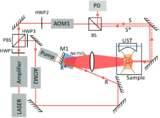
coherent with the references to use our amplifier as a phase conjugate mirror (see fig. 3). The phase conjugate beam is isolated from the original signal by a 50/50 non polarizing beam splitter cube and sent on a Thorlabs PDA36A-EC photodiode. The signal from the photodi-ode is recorded with an ADLINK-PCI9646D acquisition board in the computer driven by MatLab r . The board is triggered by the laser pump so the acquisition starts when the pump fires a pulse. Both reference and sig-nal are modulated at 80MHz using AAOptoelectronics acousto-optic modulators. These modulators are used as fast shutters and also to record the noise by shifting the frequency of one beam in order to cancel the PC beam and measure parasitic light.
Fig. 3. Phase conjugation setup. PBS, polarizing beam splitter; BS, 50/50 beam splitter; HWPi, ith half wave plate; AOMi, ith acousto-optic modulator; PD, photodi-ode detection of the phase conjugate signal; UST, ultra-sonic transducer with center frequency f=2.25MHz; M1, high-reflectivity coating @1064 nm
In order to characterize our system, we have looked at the reflectivity of the PC mirror – defined by R =
PS∗
PS – where PS∗ is the power of the phase conjugate
beam and PS is the power of the input signal beam. We
initially worked without a sample, and used light coming directly from the Nd:YAG laser. The PC reflectivity is plotted as a function of the signal input power PS in
fig. 4 with different reference power PR. We can see that
our system has a reflectivity that varies between 10% and 30%, depending on the conditions. It seems that the greater PR, the greater the reflectivity.
Now that our PC mirror works with a plane wave, the final step is to use it with a speckle from a multi-scattering medium as the signal and see if it is possible to detect an acousto-optical signal. The pumped volume is around 0.4mm3 which contain around 2.5x10⁴speckle
grain according to wavelength and the NA of the system. Our sample is a few millimeters thick slice of chicken breast held between two slabs of plexiglass. The thick-ness of the sample is controlled using chocks made with several 1mm thick microscope slides. In order to keep enough power to go through several millimeters of scatte-ring sample, the reference power is around PR= 150mW.
This value has been chosen after a few experiments
10−1 100 0 10 20 30 40 I sig (W/cm 2 ) PC Reflectivity (%) Iref = 35W/cm2 Iref = 16W/cm2 Iref = 8W/cm2
Fig. 4. Reflectivity of the phase conjugate mirror as a function of the signal power for different reference power.
ing scattering samples with a thickness between 2 and 5 millimeters. The chicken is illuminated with a power of 550mW and the light coming out is collected by a lens (f = 5 cm, NA = 1) in a 2f configuration. In order to send ultrasound in the chicken breast, the sample holder is placed under an ultrasonic transducer immersed into a water tank. The transducer sends one short burst con-sisting of several cycles of a sinusoid at fU S = 2.25MHz
generated by a Tektronix signal generator and a 25W RF amplifier. The generator is triggered by the signal used to trig the acquisition board, i.e., the pulse from the pump.
The figure 5.a shows a part of the temporal phase con-jugate signal as the pulse from the pump is launched. In this experiment, the sample was a 5mm thick piece of chicken breast. The acquisition board samples the sig-nal at 40MS/s and enables to average the sigsig-nal over 100 times in order to have a clear signal. The solid and the dotted lines respectively represent the signal with and without ultrasound. The burst last 5 cycles – giving a resolution around 3mm – and is fired 200µs after the pump pulse. Despite fluctuations, the hole caused by the passage of the ultrasonic burst within the scattered light inside the sample is clear.
Fig. 5. (a)Temporal signal witout US and with US; (b)2D scan of the chicken breast
In order to have a better visualization of the acousto-optic signal, both signals (with and without ultrasound) have been corrected by subtracting a baseline calculated by fitting the curve with a linear model. Moreover, the signal has been inverted in order for the hole to appear as a peak. An attempt of doing a 2D image of the light scattering pattern within the sample has been made by scanning transversally the ultrasonic transducer with a
high precision motor, and the resulting image is shown in fig 5.b. In this image, we can see the light spot at a depth of 2.5mm in a 5mm thick piece of chicken breast, corresponding to 5l∗ (the transport mean free path in
biological tissue is around 1mm). In those conditions, the spot of the scattered light at the imaging depth is 2-3mm wide, which is close to what appears on the scan. One of the next step for the experiment is to expand the spot both by using thicker sample and also by us-ing a divergent or an expended beam to light the sample. As a conclusion, various detection methods exist in order to retrieve the acousto-optical signal coming from a multi-scattering sample. Currently, the most commonly used are holography in photorefractive crystals or digital holography using camera and SLM. These technics have shown good results but have never been tested in vivo where their response time could be a problem for imaging. An alternative to this problem could be the use of gain media such as Nd:YVO4. Its
ability to amplify light gives this method the necessary sensitivity to detect the acousto-optical signal and its fast response time practically avoids sensitivity to speckle decorrelation. The experiments described in this letter shows promising first results with vanadate, the next steps are to study the influence of the pumping (especially the length of the pulse and the time be-tween two pulses), reduce the noise coming from the spontaneous emission of the crystal, by thinking of new pumping configuration for example, and also investigate the possibility of two-wave mixing.
The authors gratefully acknowledge the D´el´egation g´en´erale de l’Armement, the Agence Nationale de la Recherche under the project ICLM-ANR-2011-BS04-017-01, and finally the LABEX WIFI (Laboratory of Excellence with the French Program ”Investments for the futur”) under the reference ANR-10-IDEX-0001-02 PSL* for financial support.
References
1. D. S. Elson, R. Li, C. Dunsby, R. Eckersley, and M.-X. Tang, Interface Focus 1, 632 (2011).
2. S. Farahi, G. Montemezzani, A. A. Grabar, J.-P. Huig-nard, and F. Ramaz, Opt. Lett. 35, 1798 (2010). 3. P. Lai, X. Xu, H. Liu, and L. V. Wang, J. Biomed. Opt
17, 030506 (2012).
4. M. Lesaffre, S. Farahi, M. Gross, P. Delaye, C. Boccara, and F. Ramaz, Opt. Express 17, 18211 (2009).
5. Y. M. Wang, B. Judkewitz, C. A. DiMarzio, and C. Yang, Nat. Comm. 3, 928 (2012).
6. M. Gross, P. Goy, B. C. Forget, M. Atlan, F. Ramaz, A. C. Boccara, and A. K. Dunn, Opt. Lett. 30, 1357 (2005).
7. A. Brignon, G. Feugnet, J.-P. Huignard, and J.-P. Pocholle, J. Opt. Soc. Am. B 12, 1316 (1995).
8. M. J. Damzen, A. Boyle, and A. Minassian, Opt. Lett.
30, 2230 (2005).