HAL Id: hal-01303557
https://hal.inria.fr/hal-01303557
Submitted on 18 Apr 2016
HAL is a multi-disciplinary open access
archive for the deposit and dissemination of
sci-entific research documents, whether they are
pub-lished or not. The documents may come from
L’archive ouverte pluridisciplinaire HAL, est
destinée au dépôt et à la diffusion de documents
scientifiques de niveau recherche, publiés ou non,
émanant des établissements d’enseignement et de
Integrated Environment for Verifying and Running
Distributed Components
Ludovic Henrio, Oleksandra Kulankhina, Siqi Li, Eric Madelaine
To cite this version:
Ludovic Henrio, Oleksandra Kulankhina, Siqi Li, Eric Madelaine. Integrated Environment for
Ver-ifying and Running Distributed Components. Fundamental Approaches to Software Engineering,
Perdita Stevens; Andrzej Wąsowski, Apr 2016, Eindhoven, Netherlands. pp.66-83,
�10.1007/978-3-662-49665-7_5�. �hal-01303557�
Integrated environment for verifying and
running distributed components
Ludovic Henrio1, Oleksandra Kulankhina1,2, Siqi Li3, and Eric Madelaine1,2
1
Univ. of Nice Sophia Antipolis, CNRS, France, [email protected]
2 INRIA Sophia Antipolis M´edit´erann´ee, France
{Oleksandra.Kulankhina, Eric.Madelaine}@inria.fr
3 Shanghai Key Laboratory of Trustworthy Computing, ECNU, Shanghai, China
Abstract. This paper targets the generation of distributed applications with safety guarantees. The proposed approach starts from graphical specification formalisms allowing the architectural and behavioral de-scription of component systems. From this point, the user can auto-matically verify application properties using model-checking techniques. Finally, the specified and verified component model can be translated into executable Java code. We implement our approach in a tool suite distributed as an Eclipse plugin. This paper also illustrates our approach by modeling and verifying Peterson’s leader election algorithm.
1
Introduction
Component-oriented programming has become a popular approach for distributed application development. Components enforce a clear design and specification stage of the applications, and provide a solid basis for safe and modular devel-opment of complex systems. This work aims at including systematic verification of behavioral properties in the development process of component-based appli-cations. For this purpose we would like to provide the developers of distributed component-based systems with a set of tools supporting rigorous design and implementation of safe applications. Our tools should guide the user through all crucial phases of component software development: from application design specification to verification of the designed architecture and behavior properties as well as automated code generation.
Applying static analysis on hand-coded programs is complex and often im-precise, especially for distributed systems. Instead we chose a Model-Driven En-gineering and a component-oriented approach in which the structure of the ap-plication is directly specified by the developer, and in which the final code is generated automaticaly, partialy or totaly.
VerCors4is a software platform which aims at supporting the creation of safe distributed component-based applications. VerCors5 includes a set of graphical
4
https://team.inria.fr/scale/software/vercors/vcev4-download/
5
designers based on UML where the user can specify the architecture and the business logic of his application, and check the static correctness of the compo-nent architecture [1]. The specification is then automatically transformed into a behavior graph that can be model-checked to prove its correctness. We rely on model-checking for verification, but we want to hide as much as possible the com-plexity of the underlying formal techniques to make our tools accessible to non-experts in model-checking. VerCors uses parametrized networks of asynchronous automata (pNets) as an intermediate format for behavior modeling and relies on CADP [2] model-checker to verify temporal properties. Last, Java code of the modeled application can be automatically generated and executed. We rely on ProActive6and the Grid Component Model (GCM) [3]. We chose GCM/ProAc-tive because it targets distributed systems and features a well-defined semantics. Because of the chosen verification methodology, the current platform can only verify finite-state systems, but infinite-space systems can already be specified, modeled as pNets, and executed.
This paper shows that our approach is suitable for applications involving complex interactions between processes but without too much computational complexity. For the case studies involving such a computational complexity the model-checking approach might be limited. However in that case we advocate the use of the VerCors platform to specify and verify the core of the applica-tion, abstracting away computational details. The user can still generate the executable skeleton of the verified core application. He can then extend it with computational details. While the application logic is unchanged, the behavioral properties will still be valid.
The VerCors platform has already undergone several major generations, with significant evolutions for the underlying semantic model, as well as the modeling platform and the specification formalisms. The original version was using UML component structures for describing the application architecture, but this was too far from GCM needs, hence a new DSL and graphical formalism were de-fined. At the same time, aiming at better support for maintenance and usability, VerCors was moved to an Eclipse-based environment [4]. A series of publications described the support for several features of distributed component-based sys-tems, including group communications, first-class futures, and reconfiguration. At that time, the platform was only able to generate part of the behavioral model and it relied on several manual steps only realizable by experts in formal methods. No code generation was supported. Starting from that preliminary work a new VerCors tool is presented in this paper. It includes the full set of modeling formalisms (architecture, types abstractions, and state-machines), the validation of static correctness, the full chain of tools for the generation of a pNet model for model-checking, as well as a new tool for automatic generation of executable GCM/ProActive code. More recently, theoretical papers defining the pNet model [5] and the behavioral semantics of GCM in terms of pNets [6] were published. They build a formal foundation for the VerCors tools.
6
First, Section 2 presents the background on GCM, the pNets formalism and our use-case (Peterson’s leader election algorithm). In Section 3 we introduce a set of graphical formalisms to define abstractions of distributed component-based system architecture and behavior. In Section 4 we show how the speci-fied models can be transformed into behavioral graphs accepted as input by a model-checker. We present in Section 5 the generation of executable code from the model specification. Finally, we discuss the related work in Section 6 and conclude in Section 7. We illustrate our contributions by modeling, verifying, and running Peterson’s leader-election algorithm7[7]. An extended version has been published as a research report [8]; it includes appendices with details on the usecase, the architecture of the tool, and the generation process.
2
Background
2.1 Grid Component Model and ProActive platform
The Grid Component Model (GCM) [3] targets large-scale distributed compo-nent systems. Its reference implementation is GCM/ProActive.
Architecture. A GCM application consists of components, interfaces and bind-ings. Figure 2 illustrates an example of a GCM system. A component can be ei-ther composite (it consists of oei-ther subcomponents), e.g. Application, or prim-itive (a simple element encapsulating business code), e.g. Comp1. Components communicate through interfaces of two types: client and server (e.g. C1 and S1 correspondingly). A component sends requests and receives replies through client interfaces; a component receives requests and sends back results through server interfaces. The interfaces that communicate are connected with bindings.
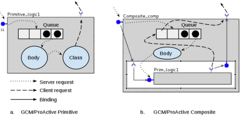
ProActive is a Java library for distributed computing. Every component in GCM/ProActive is an active object made of a single applicative thread. Informal semantics of ProActive components. Figure 1.a illustrates treat-ment of requests by primitive components. Every primitive component has a FIFO request queue, a body and an active object that serves requests. All re-quests to the server interfaces are first dropped to the queue. The body takes the first request from the queue and triggers the execution of the correspond-ing method of the active object. To process a request the component may need additional services provided by the other components, using operations calls on its client interfaces. Once a request is served, the component sends back a reply consisting of the value returned by the method. Then, the next can be served.
Figure 1.b illustrates the behavior of a GCM/ProActive composite. A com-posite has a FIFO request queue, a body, an associated active object, and some subcomponents. The body takes requests from the queue and forwards them to the subcomponents that serve them. In order to serve a request, a subcomponent may need to call methods of other subcomponents or outside of the composite, using client interfaces. Once a request has been served by the subcomponent, the composite receives the reply and forwards it to the requester. Every request sent
7
Fig. 1. GCM/ProActive component behavior
from a subcomponent towards the outside of a composite passes by the queue of the composite before being forwarded through the composite client interface. GCM components communicate using futures. When a component sends a request to another component, the caller continues its execution as long as it does not need the result of the request. When the result is needed the caller blocks automatically. We call this behavior a ”wait-by-necessity”. In the meantime, an empty object called future represents the result of the request.
2.2 pNets
Parametrized networks of asynchronous automata (pNets) have been formalized in [5]. pNets are composition of labeled transition systems with parameters; they are used as an intermediate model for encoding behavior of GCM-based applica-tions. The behavioural semantics of GCM has been formalized in [9,6]. A pNet is a hierarchical structure where leaves are pLTSs. A pLTS is a labelled transition system with variables, where labels are of the form hα, eb, (xj:= ej)j∈Ji, where eb is a guard, the variables xj∈ P are assigned when the transition is triggered, finally α is a parametrized action that has a label and a set of arguments, some of them are input variables, others are output expressions. By convention, we anno-tate actions with ”!” and ”?” depending on the information flow. We assume that the information goes from !α to ?α. A pNet is either a pLTS or the composition of several pNets; in the second case, the possible interaction between sub-entities are specified by synchronisation vectors: pNet , pLT S | hhL, pNeti∈Ii , SV
k∈K k ii where L is the set of global actions, pNeti∈Ii is the family of sub-pNets. SVk∈Kk is a set of synchronization vectors. SVk = α
j∈Jk
j → α0k means that each of the sub-pNets in the set Jk can perform synchronously an internal action αj; this results in a global action α0k. Elements not taking part in the synchronization are denoted − as in: < −, −, α, − >→ α.
2.3 Peterson’s leader election algorithm
Distributed processes often need to select a unique leader. Peterson’s election algorithm [7] can be used for this purpose in a unidirectional ring of asynchronous processes. Every process participating in the elections has a FIFO queue and the order of sent messages is preserved by the communication channels. Each process can be either in active mode if the process participates in the election, or in passive mode if it only forwards messages. Initially, every process stores a unique number that will be modified during the election. The processes exchange two rounds of messages so that every active process learns the numbers stored by the two nearest active processes preceding it. If the maximum of the two previous values and the value held by the current process is the value received from the nearest predecessor of the process, then the active process takes this value as its own value; otherwise the process becomes passive. The rounds of messages and local decision steps are repeated until a process receives its own number, this process is the leader.
In details, every process P stores variables max(P ) and left(P ). Max(P ) is the number stored by P . Left(P ) is the number of the active process on the left of P . Processes exchange messages of the form M (step, value) where step is the phase of the algorithm. At the preliminary phase, each process Pi sends M (1, max(Pi)) to its neighbor. Then, if an active process Pi receives a message M (1, x) and x is equal to its own number, the process is the leader, otherwise it assigns x to left(Pi) and sends M (2, x) to its neighbor. When an active process Pi receives M (2, x) it compares left(Pi) to x and max(Pi). If left(Pi) is greater than both values, Pi assigns left(Pi) to max(Pi) and sends M (1, max(Pi)); otherwise Pi becomes passive.
3
Graphical designer
VerCors includes a graphical designer for modeling component-based system ar-chitecture and behavior. These models must be precise enough to be translated into both input for validation and for executable code. The graphical specifica-tion part of VerCors is based on EclipseIDE; it was implemented using Sirius8. The VerCors platform includes graphical designers for four types of diagrams: Components, UML Class, UML State Machine, and Type diagrams. This section describes the four editors and the way they are integrated.
3.1 Architecture specification
Component diagrams are used for the specification of a distributed application architecture. A component diagram includes primitives (grey boxes), and com-posites (white rectangles with grey border). Interfaces are attached to the bor-ders of their containers. An interface has a set of characteristics, e.g. whether an
8
Sirius is an open-source Eclipse project for development of graphical modeling envi-ronment based on EMF and GMF: http://www.eclipse.org/sirius/
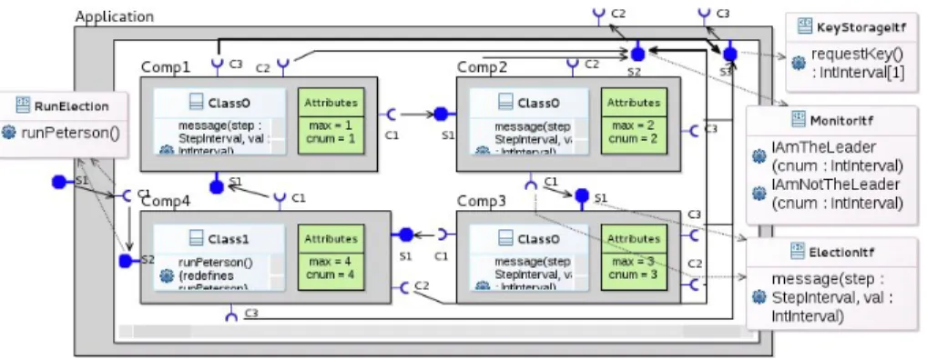
Fig. 2. Components diagram
interface is server or client. The icon representing an interface changes depending on the characteristics. Bindings are shown as arrows between interfaces.
UML Class diagrams are used to specify the list of attributes stored by components and the list of operations a component offers. The user can attach a UML class to a primitive component and a UML interface to client and server interfaces. If a class is attached to a component, it means that the attributes of the class are stored by the component and the operations of the class define the business logic of the component. A UML interface attached to a client or a server GCM interface stores the list of operations that can be called and served with this interface. Each operation defined in a class either has a reference to the operation of the interface it implements (or redefines in UML terms), or is a local method of the component.
The types of operations, attributes, and variables can be declared using Type diagrams. Enumerations, integer intervals, records (C-like structs) and infinite integers can be specified, while boolean and void types are created by default.
Use-case example The Component diagram representing the architecture of our use-case model is shown on Figure 2.
Application is a composite; it includes four primitives that participate in the leader election process. The primitives are connected in a ring topology and have similar structure. The entry point of the system is the runPeterson() operation of Application server interface S1. This request is forwarded to Comp4 that triggers the election process. During the election, components invoke method message on their client interfaces C1. As defined in Section 2.3, each message transmits two parameters: step and val. The message is transmitted to the server interface S1 of the called component. The signature of message is specified in a UML interface ElectionItf. If a component decides to become a leader or a non-leader, it reports its decision to the environment by invoking an IAmTheLeader(cnum) or an IAmNotTheLeader(cnum) method on its client interface C2. These operations take the identifier of the component as a parameter.
All four components have the same set of attributes. They have the mes-sage(...) method implementing the leader election algorithm and a set of meth-ods to access local attributes. Comp4 implements an additional operation run-Peterson(). Comp1, Comp2, and Comp3 are implemented by Class0 while Comp4 uses Class1 that extends Class0 with runPeterson() operation. Initially, the components should have different default values of attribute max and cnum. cnum is a static unique identifier of a component. To specify the values of those at-tributes for every component individually, we define them in the Atat-tributes field represented as a green box in every primitive definition.
In our model we define two integer interval types on Type diagram : StepIn-terval = 0..2 for the parameter step of messages and IntInStepIn-terval = 1..4 for the component unique identifier.
3.2 Behavior specification
UML State Machine diagrams are used for behavior specification in VerCors. Each State Machine defines the behavior of an operation of a UML Class.
A State Machine has a set of states connected by transitions. A state stores its name, while logic code is specified on transitions. To enable behavioral anal-ysis we specify the syntax of UML transitions: a transition has a label of the form [guard]/action1....actionN where Guard is a boolean expression and an action is an assignment or a method call (to a local operation or a client interface). This set of actions is sufficient to encode any behaviour of distributed objects; control structures have to be encoded as guards on transitions.
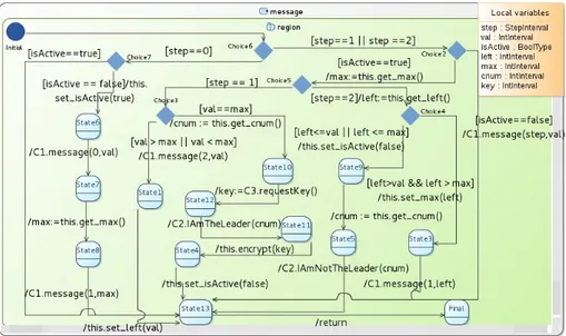
The VerCors UML-based editors are based on Obeo UML Designer9. In par-ticular, we integrated the State Machines graphical designer of Obeo UML De-signer into VerCors, adding local variable declarations. A State Machine has access to its own local variables, to the client interfaces and to local methods of the component which behavior the State Machine describes. A State Machine can access the attributes of the component but only through getters and setters. Figure 3 illustrates the State Machine of the message method of Peterson’s leader election algorithm. It uses seven variables where step and val are input parameters of the method. The initial state is illustrated with a blue circle. First, Choice6 checks the phase of the election algorithm. If the algorithm is in the preliminary (zero) phase either the component is active – it already participates in the election – or the component triggers the election process on its neighbor and performs the preliminary phase described in Section 2.3. If it is not the preliminary phase, either the component is passive and the message is forwarded to the neighbor [isActive==false]/C1.message(step,val), or the actions of the State Machine correspond to the two cases M (1, x) or M (2, x) depending on the value of step (see Section 2.3).
To illustrate future-based communications in VerCors, we extend our use-case as follows. If a component decides to become the leader, it sends a re-questKey() invocation on its client interface (see the transition from State10 to
9
Fig. 3. Message State Machine
State12). The request is forwarded to outside of Application. Then, the com-ponent claims itself as the leader by sending an IamTheLeader(cnum) request. Finally, the component calls its local method encrypt(key) using the result of requestKey() as a parameter. The component should be able to claim itself as the leader before it receives the result of requestKey(). However, it cannot exe-cute encrypt(key) if the key is not obtained. The VerCors user does not need to explicitly model future-based communications. Whenever a State Machine has a non-void client method invocation, it is interpreted as a future-based one.
To conclude, four integrated diagram editors are implemented in VerCors. Component diagrams correspond to architecture specification, Class diagrams represent attributes and method signatures of components, State Machine dia-grams are used for behavior specification, and Type diadia-grams define type ab-stractions. They allow the user to easily describe his/her application and provide sufficient input both for model-checking and for code generation.
4
Behavior verification
From user-defined architecture and behavior models VerCors produces input data for the CADP [2] model-checker following a chain of transformations pre-sented in this section. First, we analyze input models and generate a corre-sponding pNet structure. Second, we generate a finite graph given as an input to CADP, together with auxiliary scripts for managing state-space explosion. Finally, the user can specify the properties that he wants to check on the gener-ated graph and run CADP. While the specified system and the pNet model rely
on parameterized state-machines potentially featuring infinite state-space, the model-checking phase can handle finite state-space only. As a consequence, the correctness of the finite abstraction should be checked by abstract interpretation techniques. From another point of view, the pNet model could also be checked by a different tool that handles infinite state-space.
4.1 From application design to pNets
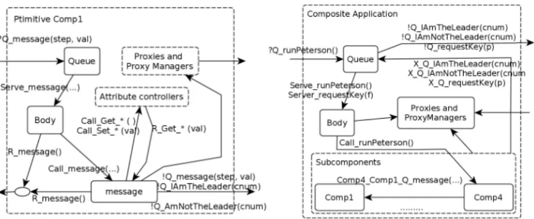
We present here the generation of pNets specifying the application behavior [6]. A pNet of a primitive assembles pLTSs of two types: the generic ones whose structure is identical for all primitives (e.g. queue, body) and the pLTSs gener-ated from the user-defined State Machines (server and local methods behavior). Figure 4 shows the pNet generated for Comp1 of our use-case. An Attribute controller pLTS is generated for each attribute of a primitive; it allows stor-ing and modifystor-ing the value of this attribute. The list of component attributes can be derived from the UML Class of the component. Proxy and Proxy-Manager pLTSs are generated for every client operation having a non-void result. They model the implementation of the futures mechanism. A pLTS is generated for each server and local method. For this purpose we translate UML State Machines specifying methods behavior into pLTSs. To translate a State Machine into a pLTS we first map each state of a State Machine into a pLTS state and each transition to one or several pLTS transition (poten-tially adding intermediate states). For example, a State Machine transition [isAc-tive==true]/max:=this.get max() involves one guard condition and two actions: a call to a local function get max and a return of its result. A pLTS transition can perform at most one action, hence, the result of the translation will consist in two sequential transitions.
The behavior of the components is modeled by synchronization vectors, ex-pressing the synchronization and the data flow between pLTSs. As an example, the Body and the Queue pLTSs of a primitive are synchronized using:
<!Serve message(...), ?Serve message(...), −, −, −, −, − >→ Serve message(...)
in which, the subnets occur in the following order:
< Queue, Body, message, max ac, cnum ac, lef t as, isActive ac >.
Synchronization of the Queue with the environment under reception of a request is expressed by: <?Q message(...), −, −, −, −, −, − >→?Q message(...), meaning that this action is exposed at the next level of pNet to synchronize with an-other pNet. The an-other vectors synchronize the following entities: the Body and a server method pLTS (Call message(...)); a server method pLTS and other local methods, or client method of the environment; the server method, the Body and the environment to return the result (R message(...)); the environment and the Queue when the Queue is saturated, raising an Error queue event.
The pNet of a composite assembles pLTSs for queue, body and sub-entities enabling futures mechanism with pNets of the subcomponents. The request re-ception mechanism is similar to the one of a primitive. The only difference is that the body is synchronized with subcomponent pNets in order to forward them the requests. pNets of subcomponents are synchronized with each other
Fig. 4. pNet of Comp1 Fig. 5. pNet of Application
under internal method invocation (e.g. Comp4 Comp1 message(...)) and result reception. If a subcomponent invokes an operation outside of the composite, it synchronizes with the composite queue. Then, the queue synchronizes with the environment and forwards the request to outside of the composite.
Scenario. The user can specify a Scenario State Machine, encoding the le-gal sequences of actions performed by the environment, accessing only the server interfaces of the root component. The scenario of our use-case calls the runPeter-son method on interface S1 of Application once. The scenario State Machine is translated into a pLTS and synchronized with the queue of the root component. This leads to a much smaller and meaningful behavior model.
4.2 From pNets to Model-Checking
Generation of verification input. As the next step, VerCors translates the pLTSs into the Fiacre format [10] and the synchronization vectors into EXP [11]. Then, the FLAC compiler translates the Fiacre specification into Lotos code. Finally the CADP front-end generates a labelled transition system in a format that can be used by the CADP model-checker. We generate a set of scripts for managing the execution of all steps: communication hiding, minimization, and hierarchical product using EXP files. In order to limit the state-space explosion phenomenon inherent to explicit-state model-checkers, the user should:
• use a scenario to limit acceptable inputs of the modeled system,
• specify the internal actions that he does not want to observe during model-checking (we generate a script transforming them into internal actions), • limit the size of the data domains using the Types diagram.
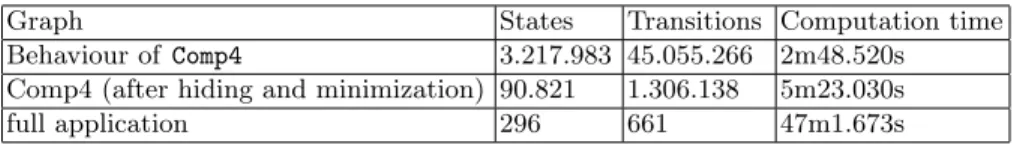
All generated transition systems are minimized using branching bisimulation. We have used the VerCors model-generation function to produce Fiacre, EXP and auxiliary scripts for our use-case. Table 1 presents size information for some of the intermediate behavior graphs. The last line is for the hierarchical
con-Table 1. Behavior graph files (all with Queue size of 3)
Graph States Transitions Computation time Behaviour of Comp4 3.217.983 45.055.266 2m48.520s Comp4 (after hiding and minimization) 90.821 1.306.138 5m23.030s
full application 296 661 47m1.673s
struction of the full model of the application (including the Scenario), and the time includes the whole model-generation workflow. The time needed to generate Fiacre, EXP files and scripts from VerCors is neglectible.
Model-checking. We use the Model Checking Language (MCL [12]) to express the behavioral properties we want to prove on our system. MCL is a very expres-sive logic including first order predicates for the data part, and the alternation free µ-calculus for branching time logics. On top of MCL, we use Specification Patterns [13] for easier expression of some usual temporal logic properties, as in the examples below. We recall that in our example the properties are evaluated in the context of the scenario where the election algorithm is triggered.
First, we check that after a call to runPeterson(), it is inevitable (under fairness hypothesis) that either the leader is elected or one of the queues is saturated. The model-checker answers true: the election terminates. We also proved that with adequate queue size, they never saturate.
[’Call RunPeterson’] Inev (’Q IamTheLeader.*’ or ’ErrorQueue.*’) Then, we prove that the event Q IamTheLeader is emitted only once:
Absence Before (’Q IamTheLeader.*’, ’Q IamTheLeader.*’)”
In order to check that the communications in the generated graph are indeed implementing futures properly, we verify the following formula which states that a key is always received before IamTheLeader() is invoked:
Existence Between(’R RequestKey.*’, ’Q requestKey.*’, ’Q IamTheLeader.*’) The model-checker answers false and provides an example of system be-havior where IamTheLeader() method is invoked before the key is received. This proves that a component is not blocked if the key is not needed.
To summarize, from the graphical models provided by the user we automat-ically generate a behavior description in the form of pNets, and translate these into an input for CADP verification tools. We tested our approach on our use-case and proved by model-checking the correctness of the application, including its safety, termination, and functional correctness.
5
Code generation and execution
5.1 Executable code generation
From the specified architecture and behavior we automatically generate exe-cutable code. We produce an ADL (XML) file defining architecture, and Java interfaces and classes files for the implementation of the methods specified by State Machines. This code can be run using the GCM/ProActive Java library.
Listing 1.1. Generated Java code of message 1 B o o l e a n i s A c t i v e = n u l l ; 2 I n t e g e r l e f t = n u l l , max = n u l l , cnum = n u l l ; 3 S t a t e c u r S t a t e = S t a t e . I n i t i a l ; 4 while ( true ) { 5 switch ( c u r S t a t e ) { 6 . . . 7 case C h o i c e 2 : 8 i f ( i s A c t i v e == true ) { 9 max=t h i s . g e t m a x ( ) ; 10 c u r S t a t e = S t a t e . C h o i c e 5 ; 11 break ; } 12 e l s e i f ( i s A c t i v e == f a l s e ) { 13 C1 . m e s s a g e ( s t e p , v a l ) ; 14 c u r S t a t e = S t a t e . S t a t e 1 3 ; 15 break ; } . . . } ; }
We generate a Java interface for every UML interface and a Java class for every UML class. We translate each State Machine attached to a method into Java code. To do this we use a Java enumeration representing the state machine steps, a local variable curState holds the current state of the state machine and actions are taken depending on this state. Listing 1.1 shows a skeleton of the encoding of the message operation from Figure 3. Note that if-else state-ments are used for states with more than one outgoing transition. For exam-ple in Choice 2, the guard label [isActive==false] is translated as an if-else statement in line 12; depending on the result, a message invocation is emit-ted (corresponding to C1.message(...), line 13) and the value of curState is updated (line 14). A drawback of this approach is that such code may not be very convenient for the programmer since do-while, for, while constructs cannot be written as such in the state machine, but will rather be encoded within the state structure, separated by case instructions. We also generate skeleton code for getter and setter methods, which have no associated state machine.
The Java code generated by VerCors relies on futures. To implement their generation, we analyze the State Machines and mark the variables that store remote method invocation results. This information is used to generate the types of those variables and to access their values. For example, the key variable from our use-case State Machine will be generated with an IntWrapper type10. Then the statement this.encrypt(key) requires the value of key and it will be translated to the following Java code: this.encrypt(key.intValue()).
5.2 Code execution
We generated ProActive/Java code of our use-case example; the resulting ex-ecution is shown in Figure 611. Black arrows represent request emissions (the
10basic types need to be wrapped to enable future-based commnuications 11
We use a dedicated tool for the visualization of ProActive program execu-tion: https://github.com/scale-proactive/A-viewer-tool-for-multiactive-objects.git
Fig. 6. Code execution
figure only shows some of them). Yellow and blue rectangles show request pro-cessing. For example, we can see how the call to runPeterson of Application is transmitted to Comp4 and at the end of the runPeterson request processing Comp4 triggers the elections on Comp1 by calling message(0,1). At the end of the algorithm execution we can see how Comp3 reports to the Application that it is not the leader and Comp1 claims to be the leader.
To sum up, from the specification provided by the user VerCors automatically produces executable ProActive/Java code. We generated and executed code of our use-case model and we observed expected behavior of the produced system. The generated code is guaranteed to verify the temporal properties proven on the model. It can either be used as it is or serve as code skeleton if the programmer wants to add computational steps that he did not include in the model.
6
Related Work
There exist a number of languages, formalisms, and tools aiming at verifica-tion and safe code generaverifica-tion, we focus here on the ones that are dedicated to distributed systems and composition of distributed systems.
BIP (Behavior Interaction Priority) [14] allows rigorous design of complex component-based systems. BIP is supported by a toolset including translators of various source models to BIP, code generators, and verification mechanisms. BIP focuses on the design of systems based on the notion of interacting entities whereas our approach takes the point of view of the software developer, using classical UML-based descriptions augmented only by our graphical DSL for ar-chitecture, relying on notions the user knows well. Our approach is closely tied to the notion of distributed components interacting by requests and replies; while this reduces the field of applicability of our work, it allows us to generate the component interaction automatically, without additional input from the user.
Cadena[15] is a platform for the development of component-based applica-tions, initially targeted for the Corba Component Model (CCM), and more re-cently extended to support Open-CCM, EJBs, and sensor networks specified with the nesC language. Cadena allows the user to specify component types, define and analyze inter-component dependencies, specify and model-check cor-rectness properties, generate code in the various component formalisms, and
even specify new user-defined component models. Unlike VerCors, it does not manage hierarchical components, so it could not be used for Fractal or GCM.
Palladio [16] is a tool for design, analysis and generation of hierarchical large-scale component-based systems. Palladio has less restrictions on types and allows more expressive modeling than VerCors. However, while Palladio has strong em-phasis on simulation and system performance prediction, our approach benefits from the use of formal methods for validation.
Creol [17] is an object-oriented programming language based on concurrent objects that communicate asynchronously. Creol is supported by the Credo [18] toolset. In Credo the application description relies on Reo [19]. Credo provides an abstract but executable model of the application. Then, a test specification is derived to check compatibility between the two models. Creol is supported by a type-checker, a simulation and model-checking platform based on Maude. In VerCors we rely on UML-based formalisms, better known by the programmers than Reo. We also directly generate efficient code that can be executed on large-scale distributed infrastructures.
SOFA 2 [20] is a framework for distributed hierarchical component-based systems development. SOFA 2 is supported by a tool set comprising graphical designers and behavior validation instruments. SOFA 2 supports dynamic archi-tectures, multiple communication styles and transparent distribution with the help of software connectors. Validation in SOFA 2 relies on behavioral protocols that are easy to understand for the programmer. This provides developers with validation capacities that require no expertise in any general logical formalism, though the expressivity may be lower than with temporal logic.
JHelena is a framework for modeling and generation of executable code of highly dynamic ensembles of autonomic distributed components that are mod-eled using Helena [21] technique. Our approach allows modeling systems with several levels of hierarchy while to our knowledge in Helena approach the com-position only occurs at one level.
ABS [22] is a formal executable component modeling language supported by a deductive verification system Key-ABS. ABS is a powerful language for concurrent object-oriented programming, however it does not support any ar-chitectural description. The verification pattern is also quite different. Different tools for ABS either focus on specific properties (absence of deadlock for ex-ample) or use KeY to specify invariants of the program and verify them. Our approach allows us to target a wide range of properties while not asking the programmer to have the expertise necessary to write program invariants.
Concerning actor systems, the related work the closest to ours is Rebeca [23] that handles both functional and real-time verification. The first main difference between Rebeca and Vercors is the programming model: Rebeca has no future and no synchronisation operation, which makes the generation of behavioural model easier. The second one is that the Rebeca toolset does not provide a design tool or an execution platform as efficient as Vercors+ProActive. On the other side, Rebeca has strong results concerning the scalability of the approach, and the range of systems and of properties handled.
Several verification tools focus on “real-time aspects” allowing to reason on the time-sensitive properties [24]. In this section we have focused on the tools that explicitly handle asynchrony and we have not cited works on real-time systems in general.
7
Discussion and Perspectives
In this paper we presented our integrated environment for designing and im-plementing safe component-based systems. Our approach includes three main aspects. First, we provide graphical formalisms for the application architecture and the behavior specification, as well as type abstractions. The formalism ex-tensively uses UML models that makes it easy to learn and use for the program-mer. Second, we ensure behavioral correctness, by running a model-checker on the specified model. In practice, we transform graphical models into input for the CADP model-checker. As a result, the user can verify correctness properties of the modeled system even if he does not have a strong expertise in formal methods. Finally, we transform the models into executable application code. We implemented our approach in the VerCors platform and we tested it by modeling, verifying, and executing Peterson’s leader election algorithm. Our approach was illustrated by generating GCM/ProActive code but it would be easy to generate code for any actor or active-object based language, or more generally any pro-gramming model made of components interacting by asynchronous requests and replies. Beyond the academic example of this paper, we have also published a study of a fault-tolerant protocol [25], showing how to handle scalability issues in the model-checking activities. In another paper, we showed an industrial-inspired study [26] in which we handle large state-spaces modeling an application with dynamic reconfiguration of components.
This paper raises the question of the relation between the semantics of the handled models: state-machines, pNets, finite-state models, and distributed Java programs. Previous usecases show that many applications and protocols can be encoded faithfully and executed correctly. It is not in the scope of this paper to study the semantic gap between these models or to formally prove that the behavioral model has the same semantics as the generated code. However, the formal semantics of ProActive [27], the semantics of pNets [5], and the formal definition of the translation from GCM to pNets [6] allowed us to check care-fully that the semantics correspond faithcare-fully. Considering the complexity of the system, an exhaustive formal proof of bisimulation between the semantics would require several years.
While creating the VerCors platform we tackled a number of challenges. First, the choice of the underlying technology was not trivial: we experimented with the Topcased platform, UML profiles, Eclipse Papyrus, before finding a usable environment with Sirius. Second, finding an expressive and easy to learn graphi-cal formalism was a challenging task. We wanted to reuse UML notions as much as possible, but we realized that we needed our own graphical formalism, and had to find a way to map a large part of GCM specifications into UML
mod-els. Finally, the integration of all languages, models and formalisms involved in modeling, execution and verification was not trivial. For example, we had to the syntax of State Machine had to be precisely specified to be able to translate them into Fiacre. Also, the translation between formalisms raised technical difficulties, some of them detailed in [6] and others related to the Fiacre language.
We are currently working on extensions of the VerCors platform that would address more features of distributed component-based applications. In particu-lar, we want to address separation between functional code and application man-agement and verify the correct interaction between those two aspects. Another challenge that we plan to address is the expression of the application properties using a higher level specification language. This should also include the transla-tion from the model-checker diagnostics back to the user-level formalism, that is not implemented in the current version. This would make our approach even more attractive for users non-expert in model-checking.
References
1. Henrio, L., Kulankhina, O., Liu, D., Madelaine, E.: Verifying the correct compo-sition of distributed components: Formalisation and Tool. In: FOCLASA, Rome, Italy (September 2014)
2. Garavel, H., Lang, F., Mateescu, R., Serve, W.: Cadp 2010: A toolbox for the construction and analysis of distributed processes. In: TACAS’11. Volume 6605 of LNCS., Saarbr¨ucken, Germany, Springer, Heidelberg (2011)
3. Baude, F., Caromel, D., Dalmasso, C., Danelutto, M., Getov, V., Henrio, L., P´erez, C.: GCM: A Grid Extension to Fractal for Autonomous Distributed Components. Annals of Telecommunications 64(1) (2009) 5–24
4. Cansado, A., Madelaine, E.: Specification and verification for grid component-based applications: from models to tools. In de Boer, F.S., Bonsangue, M.M., Made-laine, E., eds.: FMCO 2008. Number 5751 in LNCS, Berlin Heidelberg, Springer-Verlag (2009) 180–203
5. Henrio, L., Madelaine, E., Zhang, M.: pnets: An expressive model for parameterised networks of processes. In: 23rd Euromicro International Conference on Parallel, Distributed, and Network-Based Processing, PDP 2015, Turku, Finland, March 4-6, 2015. (2015) 492–496
6. Ameur-Boulifa, R., Henrio, L., Madelaine, E., Savu, A.: Behavioural Semantics for Asynchronous Components. Rapport de recherche RR-8167, INRIA (December 2012)
7. Dolev, D., Klawe, M.M., Rodeh, M.: An o(n log n) unidirectional distributed algorithm for extrema finding in a circle. J. Algorithms 3(3) (1982) 245–260 8. Henrio, L., Kulankhina, O., Li, S., Madelaine, E.: Integrated environment for
verifying and running distributed components - Extended version. Research Report RR8841, INRIA Sophia-Antipolis (December 2015)
9. Barros, T., Ameur-Boulifa, R., Cansado, A., Henrio, L., Madelaine, E.: Behavioural models for distributed fractal components. Annals of Telecommunications 64(1-2) (2009) 25–43
10. Berthomieu, B., Bodeveix, J., Filali, M., Garavel, H., Lang, F., Peres, F., Saad, R., Stoecker, J., Vernadat, F.: The syntax and semantics of Fiacre. (March 2009)
11. Lang, F.: Exp.Open 2.0: A flexible tool integrating partial order, compositional, and on-the-fly verification methods. In: Integrated Formal Methods, 5th Interna-tional Conference, IFM 2005, Eindhoven, The Netherlands, 2005. (2005) 70–88 12. Mateescu, R., Thivolle, D.: A Model Checking Language for Concurrent
Value-Passing Systems. In Cuellar, J., Maibaum, T., eds.: FM 2008. Volume 5014., Turku, Finland, Springer Verlag (May 2008) 148–164
13. Dwyer, M.B., Avrunin, G.S., Corbett, J.C.: Patterns in property specifications for finite-state verification. In: 21st International Conference on Software Engineering. (May 1999)
14. Basu, A., Bensalem, B., Bozga, M., Combaz, J., Jaber, M., Nguyen, T., Sifakis, J.: Rigorous component-based system design using the BIP framework. IEEE Softw. 28(3) (May 2011) 41–48
15. Childs, A., Greenwald, J., Jung, G., Hoosier, M., Hatcliff, J.: CALM and Cadena: Metamodeling for Component-Based Product-Line Development. IEEE Computer 39(2) (2006) 42–50
16. Reussner, R., Becker, S., Burger, E., Happe, J., Hauck, M., Koziolek, A., Koziolek, H., Krogmann, K., Kuperberg, M.: The Palladio component model. Technical report, Karlsruhe Institute of Technology (march 2011)
17. Leister, W., Bjork, J., Schlatte, R., Griesmayer, A.: Verifying distributed algo-rithms with executable Creol models. (January 2011)
18. Grabe, I., Jaghoori, M.M., Aichernig, B.K., Baier, C., Blechmann, T., de Boer, F.S., Griesmayer, A., Johnsen, E.B., Klein, J., Kl¨uppelholz, S., Kyas, M., Leister, W., Schlatte, R., Stam, A., Steffen, M., Tschirner, S., Xuedong, L., Yi, W.: Credo methodology: Modeling and analyzing A peer-to-peer system in Credo. Electr. Notes Theor. Comput. Sci. 266 (2010) 33–48
19. Arbab, F.: A behavioral model for composition of software components. L’OBJET 12(1) (2006) 33–76
20. Hnˇetynka, P., Pl´aˇsil, F.: Dynamic reconfiguration and access to services in hierar-chical component models. In: Proceedings of the 9th int. conference on Component-Based Software Engineering. CBSE’06, Springer-Verlag (2006)
21. Klarl, A., Hennicker, R.: Design and Implementation of dynamically evolving ensembles with the HELENA framework. In: Proceedings of the 23rd Australasian Software Engineering Conference, IEEE (2014) 15–24
22. H¨ahnle, R., Helvensteijn, M., Johnsen, E.B., Lienhardt, M., Sangiorgi, D., Schaefer, I., Wong, P.Y.: HATS Abstract Behavioral Specification: The architectural view. In: Proc. 10th International Symposium on Formal Methods for Components and Objects (FMCO 2011). LNCS 7542, Springer-Verlag (2013) 109–132
23. Sirjani, M., Movaghar, A., Shali, A., de Boer, F.S.: Modeling and verification of reactive systems using rebeca. Fundam. Inform. 63(4) (2004) 385–410
24. Burmester, S., Giese, H., Hirsch, M., Schilling, D.: Incremental design and formal verification with UML/RT in the FUJABA real-time tool suite. In: Proceedings of the International Workshop SVERTS. (2004)
25. Ameur-Boulifa, R., Halalai, R., Henrio, L., Madelaine, E.: Verifying safety of fault-tolerant distributed components. In: International Workshop on Formal Aspects of Component Software (FACS’11), Oslo (Sept 2011)
26. Gaspar, N., Henrio, L., Madelaine, E.: Formally reasoning on a reconfigurable component-based system - a case study for the industrial world. In: International Symposium on Formal Aspects of Component Software (FACS 2013). Lecture Notes in Computer Science, Nanchang, China, Springer (Oct 2013)
27. Caromel, D., Henrio, L.: A Theory of Distributed Objects. Springer-Verlag (2005) ISBN 3-540-20866-6.