Characterization of Irradiation Damage of Ferritic ODS
Alloys with Advanced Micro-Sample Methods
M.A. Pouchon&J. Chen&R. Ghisleni&J. Michler& W. Hoffelner
Received: 19 May 2008 / Accepted: 1 December 2008 / Published online: 25 December 2008
# Society for Experimental Mechanics 2008
Abstract Oxide dispersion strengthened (ODS) steels are candidate materials for advanced electric energy and heat generation plants (nuclear, fossil). Understanding the degra-dation of mechanical properties of these alloys as a result of service exposure is necessary for safe design. For advanced nuclear applications combinations of temperature, irradiation and stress are important damage conditions. They are studied either with neutron irradiated samples (often highly active) or with ion-irradiated samples (irradiation damage often limited to only a few micrometer deep areas). High activity of samples and limited sample volume claim to subsized samples like nano-indentation, micro-pillar compression or thin strip creep testing. Irradiation hardening and irradiation creep were studied with these methods. Ferritic ODS steels with 19% chromium were investigated. The materials were studied in qualities differing in grain sizes and in sizes of the dispersoids. Irradiation was performed in an accelerator using He-ions. Irradiation damage profiles could be well analyzed with indentation. Yield stress determined with compression tests of single-crystal micropillars was well comparable with tension tests performed along the same crystallographic orientation. Irradiation creep of samples with different sizes of dispersoids revealed only a small influence of particle size being is in contrast with thermal creep but consistent with expectations from other investigations.
Keywords Micro-samples . Miniaturized testing . Irradiation damage . Condition monitoring
Introduction
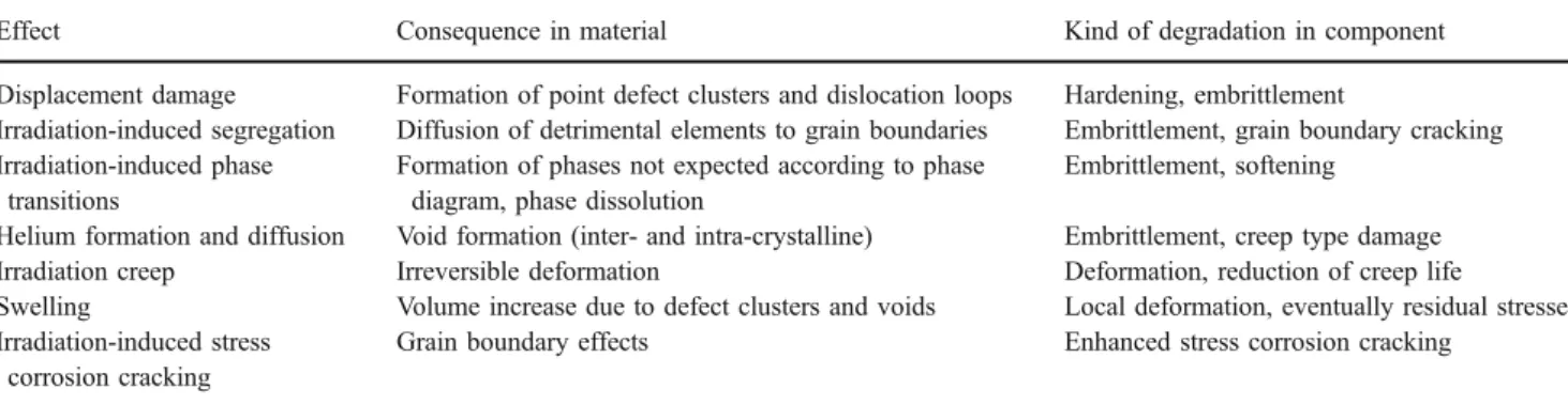
Materials for current and advanced nuclear installations are subject to a variety of exposures that degrade materials properties. In addition to creep, fatigue and corrosion also irradiation-induced effects are important. Degradation mechanisms caused by irradiation are listed in Table 1. A thorough understanding of these mechanisms is mandatory for accurate life time assessments of components with design life of up to 60 years.
According to the size of reactor components, the characterization of the materials involved is usually determined with large samples or with component type tests. In contrast to that many damage phenomena occur on a microscopic level. The multiscale approach tries to integrate the different scales to a sound assessment of component damage [1,2]. It uses a wide range of modeling techniques together with a wide range of sample sizes. Quantitative understanding of possible size effects and the link to component performance is mandatory for the success of this approach. Small samples are of particular importance for the investigation of irradiation damage because of three reasons: (1) Radiation exposure of experimentalists should be kept as low as possible. This allows only small active sample volumes to be analyzed or expensive and time consuming testing in hot cells; (2) damage due to ion irradiation which is often used for basic irradiation studies is limited to small penetration depths; (3) the possible use of sub-sized samples for damage assess-ment and condition monitoring with samples taken from specified plant locations in defined maintenance intervals.
DOI 10.1007/s11340-008-9214-5
Presented at the TMS 2008 Conference in New Orleans M.A. Pouchon
:
J. Chen:
W. Hoffelner (*)Laboratory for Nuclear Materials, Paul Scherrer Institute, CH-5232 Villigen-PSI, Switzerland
e-mail: [email protected]
URL:www.psi.ch
R. Ghisleni
:
J. MichlerEMPA Materials Science and Technology, CH-3602 Thun, Switzerland
Our investigations focus on materials for advanced future gas cooled reactors like the very high temperature reactor (VHTR) or the gas cooled fast reactor (GFR). Ferritic dispersion strengthened steels (ODS) are candidates for several in-core and out-of-core applications. In this paper we will concentrate on irradiation hardening and irradiation creep using sub-sized samples.
Materials Investigated
Work was performed with different types of oxide dispersion strengthened ferritic steels: The commercial PM2000 [3] in annealed condition and in severe plastically deformed (SPD) condition, as well as the Japanese development 19Cr ODS (K1) [4] were investigated. The main characteristics of the three materials are given in Table2.
Both qualities of PM2000 had comparable dispersoid sizes and distributions. In the annealed condition very large and elongated grains were present allowing the investiga-tion of single crystal properties. The SPD material had equiaxed grains of similar size as the ODS 19Cr grains.
Pre-treatments and Sample Preparation
A summary of pre-treatments and investigations performed is given in Table3. Ion implantation was performed at room temperature with a 4He++ beam at the Swiss Federal Institute of Technology in Zürich, using a Tandem Accelerator. To receive an acceptable damage distribution,
irradiation was performed under 4 different incident angles (ranging from 0° to 66°) with energy of 1.5 MeV. Damage as a function of depth covered a range from 0.7dpa (displacements per atom) at 1 micrometer from the surface to about 1.3 dpa at 2.5 μm from the surface. Additional details regarding irradiation procedure and associated damage profile have been previously published [5].
In situ irradiation creep under He-implantation was performed at the compact cyclotron of Forschungszentrum Juelich. Details of the experimental set up are described in Ref. [6]. The 0.1 mm thick samples were 3D-homoge-neously irradiated under constant uniaxial stress. Irradiation was performed with 24 MeV 4He++ions passing through a magnet scanning system and a degrader wheel with 24 Al-foils of variable thicknesses. More details about the experimental conditions can be found in literature [7].
Microhardness and indentation tests were performed on surfaces polished prior to irradiation. All pillars tested were fabricated with a focused ion beam instrument (FIB) using a Lyra Dual Beam from Tescan. The energy of the ion source was 30 keV Ga ion. Pillars were produced in two steps: Coarse (4 μm diameter pillars): 4.3 nA probe current, 25.1 keV condenser voltage, 400μm aperture, 50 nm spot size; fine (1 μm diameter pillars): 130 pA probe current, 24 keV condenser voltage, 50μm aperture, 10 nm spot size.
Strength and Irradiation Effects
Yield stress and ultimate tensile strength of ODS materials are mainly determined by size and distribution of the
Table 2 Chemical composition and microstructure of the investigated ODS steels
Material Dispersoid diameter [nm] Grain size [nm]3 Cr [wt%] Al [wt%] Ti [wt%] W [wt%] Y2O3[wt%] Fe
PM2000 annealed 28.0 106×106×(>107) 19.0 5.5 0.5 – 0.5 Bal.
PM2000 SPD 28.0 5003(average) 19.0 5.5 0.5 – 0.5 Bal.
19 Cr ODS 2.1 200×200×700 18.4 – 0.3 0.3 0.4 Bal.
Table 1 Most important irradiation-induced damage for structural materials in nuclear applications
Effect Consequence in material Kind of degradation in component
Displacement damage Formation of point defect clusters and dislocation loops Hardening, embrittlement
Irradiation-induced segregation Diffusion of detrimental elements to grain boundaries Embrittlement, grain boundary cracking Irradiation-induced phase
transitions
Formation of phases not expected according to phase diagram, phase dissolution
Embrittlement, softening Helium formation and diffusion Void formation (inter- and intra-crystalline) Embrittlement, creep type damage Irradiation creep Irreversible deformation Deformation, reduction of creep life
Swelling Volume increase due to defect clusters and voids Local deformation, eventually residual stresses Irradiation-induced stress
corrosion cracking
dispersoids. PM2000 annealed and PM2000 SPD have comparable dispersoid sizes and distributions (Table 2). From this point of view only a small difference between the yield stresses of PM2000 annealed and PM2000 SPD should exist. Additional contributions to the yield stress of PM2000 SPD can be expected from a higher dislocation density and grain size effects in this material. According to information from the laboratory producing this material, a 10–15% higher yield stress can be expected (Korb 2006, internal communication). The small diameter of dispersoids in the ODS 19Cr material point towards a remarkable increase in yield stress and strength. For the quality K1 a yield stress of 1142 MPa was reported [8]. These expect-ations for the as received materials were reproduced with micro-hardness tests shown in Table4.
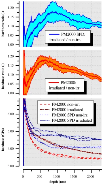
Irradiation creates point defects and leads to the formation of point-defect clusters and/or dislocation loops. These additional obstacles for dislocation movement increase the yield strength and decrease the ductility of the material. Ion implantation is a convenient way for introducing irradiation damage into a material. Damage depth is only in the micrometer range as already indicated in the introduction. The depth profile of this type of damage distribution depends on the irradiation conditions and is not homogeneous. Figure1
shows the measured hardness for PM2000 annealed and for PM2000 SPD as a function of indentation depth. The measurements were performed with a G200 nano indenter from MTS, using the continuous stiffness mode [9] and a Vickers-tip. The continuous stiffness was measured with a
superimposed sinusoidal signal of 45 Hz and 2 nm ampli-tude. The targeted indentation depth was 2.5 μm with a strain rate of 0.05 s−1. The samples were He-irradiated under the conditions already described above. The hardness profile
Table 4 Microhardness of the different ODS materials investigated (values relative to PM2000 annealed)
PM2000 annealed PM2000 SPD ODS 19Cr Micro-hardness relative to PM2000 annealed 1 1.11 1.54
Yield Stress [MPa] 720 (790–830) [(Korb 2006, internal communication
1,142 [8]
Yield stresses are given for comparison. PM2000 annealed represents the mean value from the tensile tests shown in Fig.3. For PM2000 SPD only assessments from the producer exist [Korb 2006, internal communication].
Table 3 Pre-treatments of samples and mechanical tests performed
Ion implantation Irradiation creep
Microhardness/indentation micropillar Thin strip creep
PM2000 annealed X X X X X PM2000 SPD X X ODS 19Cr X X 0 500 1000 1500 2000 3.00 4.00 5.00 6.00 PM2000 non-irr. PM2000 irradiated PM2000 SPD non-irr. PM2000 SPD irradiated hardness (GPa) depth (nm) 1.00 1.05 1.10 1.15 1.20 PM2000: irradiated / non-irr. hardness ratio (-) 1.00 1.05 1.10 1.15 1.20 PM2000 SPD: irradiated / non-irr. hardness ratio (-)
Fig. 1 Indentation profile measured with the continuous stiffness method [9] for two different qualities of PM2000 (annealed and SPD). For both qualities, an irradiated and an un-irradiated sample were measured. The upper two graphs present the hardness ratio of the irradiated and the non irradiated sample for each quality
reflects the expected profile of irradiation damage [10] except a slight shift towards the sample surface. This shift can be well understood by the plastic zone in front of the indenter tip which contains also information from material ahead. No significant differences in the irradiation profiles of the two materials was detected. This was expected because there was only a difference in grain size which should have no pronounced influence on the development of point defect clusters. More quantitative correlations can be expected from FE-analyses and further tests with different profiles.
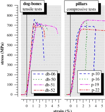
A quantitative determination of the stress–strain behavior can be obtained with micro-samples like micro-pillars. PM2000 annealed was used as sample material. As this material has very large grains it was possible to determine the stress–strain curve with single crystal tensile samples in which the development of slip bands could also be observed. In the tensile tests the load was applied parallel to the [111] direction. Micro-pillars were prepared in a way that the compressive load was also parallel to this crystallographic direction. Figure2 shows a pillar before and after deformation while Fig. 3 shows the engineering stress–strain diagram.
Micro-compression was performed with a commercial nanoindenter (MTS XP, load controlled) using a 16 um diameter diamond flat punch tip. Loading and unloading was done with a constant rate of 5μN/s. The average value of the yield stress measured with different pillars is in agreement with the yield stress determined by tensile test. This seems to be in
Fig. 2 Micro-pillar of PM2000 annealed tested parallel to the crystallographic [111]-direction before (a) and after (b) com-pression test 0 3 0 100 200 300 400 500 600 700 800 900 p-10 p-16 p-19 p-22 db-06 db-50 db-51 db-52 dog-bones tensile tests stress (MPa) strain (%) 0 3 pillars compressive tests 5 4 2 1 5 4 2 1
Fig. 3 Engineering stress–strain diagrams for PM2000 annealed, tested under tension and with micro-pillar compression. The load was applied parallel to the [111] direction for both types of experiments. The db and p values refer to sample designations
0 50 100 150 200 250 0.0000 0.0005 0.0010 0.0015 0.0020 0.0025 0.0030 573 K PM2000 19 Cr (K1)
strain-rate / dose-rate (dpa
-1)
stress (MPa)
Fig. 4 Irradiation creep of two ferritic ODS steels measured at 300°C (573 K). Steady-state creep rates per dose rate as a function of applied stress
contradiction with literature where pronounced size effects for micro-pillars and whiskers were reported (e.g. [11,12]). The absence of a clear size effect in our case may be attributed to the facts that the investigated samples are not expected to be defect free, they contain dispersoids and they do not contain any grain boundaries.
Preliminary tests with micropillars from irradiated mate-rials did not show clear results until now. Probable reasons for this could be inhomogeneity of defects in the gage section as well as high scatter of test data. Further tests with different pillar diameters, different irradiation profiles and different microstructures will help to clarify the situation.
Irradiation Creep and Thin Strip Samples
Creep of structural materials occurs not only at high temper-atures. It is also detected at moderate temperatures when irradiation and stress act simultaneously. Irradiation creep tests can be performed in accelerator beams with higher energies than the ones in which the irradiation tests described in section 4 were performed. Such tests are expensive but they are less expensive and less time consuming than creep experiments with neutrons. Neutron tests would also lead to highly activated samples. The drawback of this experimental procedure is still the limited penetration depth of ions requiring tests with thin strips (100–200 μm). Experimental constraints (availability of irradiation facilities, expenses of beam-time) are the reason why only a limited number of experiments can be performed. Questions like the relative influence of dispersoid size on irradiation creep of ODS alloys can be studied, however, also with limited amount of samples. According to earlier investigations under thermal creep conditions only negligible size effects for creep strain measurements are expected [13]. Figure 4 shows the dependence of the ratio between steady-state creep rate and dose rate as a function of the applied stress for PM2000 annealed and ODS 19Cr at 300°C. The difference between the conventional material and the advanced ODS 19Cr was not very pronounced although the difference in dispersoid size was more than one order of magnitude (Table2). This is in contrast to thermal creep where size and distribution of the dispersoids play a very important role. Mechanisms for irradiation creep are rather dependent on the nature of irradiation-induced defects then on conventional hardening mechanisms. A more detailed study of irradiation creep of these materials is given in [14].
Discussion and Conclusions
Damage characterization and life-time assessments of materi-als and components are extremely important for new
genera-tion nuclear plants (GENIV [15]). In contrast to current nuclear plants they will operate at higher temperatures (up to 1,000°C) and at high irradiation levels. Sub-sized samples provide a very good tool to study damage and damage evolution in small volumes. They can help to overcome irradiation-induced limitations (penetration depth of ions, high sample activity). However, they could also provide a tool for condition monitoring in real plants. A well substantiated understanding of possible size effects and/or other limitations of results gained with sub-sized samples is mandatory for conclusions concerning safety and reliability of components. In this paper the applicability of sub-sized samples for determination of irradiation damage was studied. Ferritic oxide dispersion strengthened steels, considered as future candidates for such plants, were taken as examples. Tests chosen were nanoindentation, micropillar compression and thin strip creep. The differences in yield strength of the materials could be well reproduced by conventional micro-hardness tests. Depth profiles of ion implanted samples determined with a nano-indenter in continuous stiffness method reproduced the expected damage profile. A determi-nation of the stress–strain response of single crystal samples with micro-pillars compression was possible and the mea-sured yield stress was in agreement with expectations from larger samples. Reasons for the absence of a size effect for this material still need further investigations. Scatter being in the range of the expected effects made it difficult to accurately determine irradiation hardening with the chosen micro-pillar size. Inhomogeneity of the damage along the gage section might be another reason. However, assuming more homogeneous damage in components let expect that micro-pillars are well suited for damage analysis under plant conditions. Further work is required to provide a thorough understanding of the stress–strain response of micro-pillars compression which is a necessary tool for component damage assessments. Thin strip creep tests can be used for the determination of creep rates under irradiation creep and/or thermal creep conditions. All together it seems that micro-samples would have a wide potential for damage assessments of highly loaded materials in future fission applications.
Acknowledgement This work was performed with in the Swiss Competence Center of Energy and Mobility (CCEM) through project “Platform for High Temperature Materials”, additional contributions came from the EU Framework 6 projects EXTREMAT and RAPHAEL.
References
1. Wirth BD, Odette GR, Stoller RE (2001) Recent progress toward an integrated multiscale-multiphysics model of reactor pressure vessel embrittlement. Mat Res Soc Symp Proc 677:AA5.2.1–AA5.2.6 2. Samaras M, Hoffelner W, Fu CC, Guttmann M, Stoller RE (2007)
Materials modeling—a key for the design of advanced high temperature reactor components. Rev Gén Nucl 5:50–57
3. Korb G, Sporer D (1990) Recrystallization behaviour of pm 2000 oxide dispersoid strengthened iron-base superalloy. In: Bachelet R, Brunetaud R, Coutsouradis D, Esslinger P, Ewald J, Kvernes I, Lindblom Y, Meadowcroft DB, Regis V, Scarlin R, Schneider K, Singer R (eds) High temperature materials for power engineering. Kluwer, pp 1417–1430
4. Kimura A (2005) Current status of reduced-activation ferritic/ martensitic steels R&D for fusion energy. Mater Trans 463:394– 404 doi:10.2320/matertrans.46.394
5. Pouchon MA, Chen J, Dobeli M, Hoffelner W (2006) Oxide dispersion strengthened steel irradiation with helium ions. J Nucl Mater 3521–3:57–61 doi:10.1016/j.jnucmat.2006.02.070
6. Jung P, Schwarz A, Sahu H (1985) An apparatus for applying tensile, compressive and cyclic stresses on foil specimens during light ion irradiation. Nucl Instrum Methods Phys Res 2342:331– 334 doi:10.1016/0168-9002(85)90925-8
7. Chen J, Jung P, Pouchon M, Rebac T, Hoffelner W (2008) Irradiation creep and precipitation in a ferritic ods steel under helium implantation. J Nucl Mater 373 1–3:22–27 doi:10.1016/j. jnucmat.2007.04.051
8. Lee J, Jang C, Kim I, Kimura A (2007) Embrittlement and hardening during thermal aging of high Cr oxide dispersion strengthened alloys. J Nucl Mat 367–370Part 1:229–233
doi:10.1016/j.jnucmat.2007.03.007
9. Li X, Bhushan B (2002) A review of nanoindentation continuous stiffness measurement technique and its applications. Mater Charact 481:11–36
10. Pouchon MA, Döbeli M, Schelldorfer R, Chen J, Hoffelner W, Degueldre C (2005) ODS steel as structural material for high temperature nuclear reactors. In: Physics of Radiation Effect and Radiation Materials Science, Vol. 86 of Problems of atomistic science and technology, Kharkov Institute of Physics and Technology, pp 122–127
11. Uchic MD, Dimiduk DM, Florando JN, Nix WD (2004) Sample dimensions influence strength and crystal plasticity. Science 13, 305(5686):986–989
12. Volkert CA, Lilleodden ET (2006) Size effects in the deformation of sub-micron Au columns. Philos Mag 86:5567–5579
doi:10.1080/14786430600567739
13. Hoffelner W, Chen J (2006) Thermal and Irradiation creep of advanced high temperature materials. Proceedings HTR2006: 3rd International Topical Meeting on High Temperature Reactor Technology October 1–4, 2006, Johannesburg, South Africa, Paper E 00000038see also: http://htr2006.co.za/downloads/ f i n a l _ d o w n l o a d _ p a p e r s / E 0 0 0 0 0 0 3 8 . p d f ? P H P S E S S I D = 38832e3d46b6d1e343651755c0025951
14. Chen J, Pouchon MA, Kimura A, Jung P, Hoffelner W (2009) Irradiation creep and microstructural change in an ods ferritic steel with very fine oxide particles after helium implantation under stress. J Nucl Mater in press
15. U.S. DOE Nuclear Energy Research Advisory Committee.Gener-ation IV InternCommittee.Gener-ational Forum, A technology roadmap for generCommittee.Gener-ation iv nuclear energy systems, Tech. Rep. GIF-002-00 03-GA50034 (Dec. 2002).http://www.gen-4.org/PDFs/GenIVRoadmap.pdf