HAL Id: hal-02388109
https://hal-mines-paristech.archives-ouvertes.fr/hal-02388109
Submitted on 1 Dec 2019
HAL is a multi-disciplinary open access
archive for the deposit and dissemination of
sci-entific research documents, whether they are
pub-lished or not. The documents may come from
teaching and research institutions in France or
abroad, or from public or private research centers.
L’archive ouverte pluridisciplinaire HAL, est
destinée au dépôt et à la diffusion de documents
scientifiques de niveau recherche, publiés ou non,
émanant des établissements d’enseignement et de
recherche français ou étrangers, des laboratoires
publics ou privés.
Nano-Structured Optical Fibers Made of
Glass-Ceramics, and Phase Separated and Metallic
Particle-Containing Glasses
Alexander Veber, Zhuorui Lu, Manuel Vermillac, Franck Pigeonneau, Wilfried
Blanc, Laëticia Petit
To cite this version:
Alexander Veber, Zhuorui Lu, Manuel Vermillac, Franck Pigeonneau, Wilfried Blanc, et al..
Nano-Structured Optical Fibers Made of Glass- Ceramics, and Phase Separated and Metallic
Particle-Containing Glasses. Fibers, MDPI, 2019, �10.3390/fib7120105�. �hal-02388109�
Fibers 2019, 7, 105; doi:10.3390/fib7120105 www.mdpi.com/journal/fibers
Review
Nano-Structured Optical Fibers Made of
Glass-Ceramics, and Phase Separated and Metallic
Particle-Containing Glasses
Alexander Veber 1,*, Zhuorui Lu 2, Manuel Vermillac 3, Franck Pigeonneau 4, Wilfried Blanc 2 and Laeticia Petit 1
1 Photonics Laboratory, Tampere University, Korkeakoulunkatu 3, 33720 Tampere, Finland; laeticia.petit@tuni.fi 2 Université Côte d’Azur, CNRS, Institut de Physique de Nice, UMR 7010, 06108 Nice, France;
zhuorui.lu@univ-cotedazur.fr (Z.L); wilfried.blanc@inphyni.cnrs.fr (W.B.)
3 ICI - Institut du Calcul Intensif Ecole Centrale de Nantes, BP 92101, 44321 Nantes, France; manuel.vermillac@ec-nantes.fr
4 MINES ParisTech, PSL Research University, CEMEF-Centre for material forming, UMR 7635, 06904 Sophia-Antipolis, France; franck.pigeonneau@mines-paristech.fr
* Correspondence: alexander.veber@tuni.fi
Received: 3 October 2019; Accepted: 25 November 2019; Published: 30 November 2019
Abstract: For years, scientists have been looking for different techniques to make glasses perfect: fully
amorphous and ideally homogeneous. Meanwhile, recent advances in the development of particle-containing glasses (PCG), defined in this paper as glass-ceramics, glasses doped with metallic nanoparticles, and phase-separated glasses show that these “imperfect” glasses can result in better optical materials if particles of desired chemistry, size, and shape are present in the glass. It has been shown that PCGs can be used for the fabrication of nanostructured fibers—a novel class of media for fiber optics. These unique optical fibers are able to outperform their traditional glass counterparts in terms of available emission spectral range, quantum efficiency, non-linear properties, fabricated sensors sensitivity, and other parameters. Being rather special, nanostructured fibers require new, unconventional solutions on the materials used, fabrication, and characterization techniques, limiting the use of these novel materials. This work overviews practical aspects and progress in the fabrication and characterization methods of the particle-containing glasses with particular attention to nanostructured fibers made of these materials. A review of the recent achievements shows that current technologies allow producing high-optical quality PCG-fibers of different types, and the unique optical properties of these nanostructured fibers make them prospective for applications in lasers, optical communications, medicine, lighting, and other areas of science and industry.
Keywords: optical fibers; glass; glass-ceramics; metallic nanoparticles; phase-separation; fabrication;
optical properties
1. Introduction
The ground-breaking discovery done in the 1960s by Charles K. Kao on fibers of very pure glass possessing very low absorption losses allowed fiber optics to transfer from the theoretical to the practical. High purity silica-glass fibers with losses of about 0.2 dB/km led to the development of fiber-optic
communications, which nowadays connect millions of people all over the world. Optical fibers became a perfect host for laser development. They can be used to measure strain, temperature, and pressure just to cite a few applications. Despite this tremendous success, the fiber-optics is still a rapid and active developing area of science.
Made of glass, optical fibers inherited all positive and negative properties of this material. Glasses are easy and inexpensive to produce on any scale and in any shape, they can possess high chemical stability and mechanical strength, and have high transparency. However, they could hardly compete, for example, with crystalline materials in thermal conductivity, or rare-earth elements’ absorption, emission cross-sections, and available transparency range. Recent advances in glass science showed that properties of this material can be significantly improved if some additional phases are formed or impregnated in the glass. In particular, advances have been achieved in the development of particle-containing glasses: glass-ceramic materials, glasses doped with metallic nanoparticles, and phase-separated glasses. To date, these particle-containing glasses have become quite common and actively used in case of the bulk materials, but are still rather new for fiber optics.
The purpose of this review is to summarize recent advances in the fabrication of structured fibers made of particle-containing glasses, their potential benefits, their actual properties, and their potential applications. The review covers three types of particle-containing glasses (PCG): crystalline dielectric particles, i.e., glass-ceramics; metallic nanoparticles (MeNPs); and dielectric amorphous particles, i.e., phase-separated glasses.
First, we consider properties of the PCG bulk materials, their potential benefits over the homogenous materials (Section 2), their fabrication (Section 3), characterization methods (Section 4) and factors influencing the transparency of these materials (Section 5). Since to a large extent we deal with the same material when referring to bulk glass and their corresponding optical fibers, ideas and methods used for the bulk materials can be applied to fibers too. Nevertheless, there are, of course, many peculiarities during the fiber fabrication process, which are considered in Section 6. The last part of the review is focused on the recent experimental advances in the fabrication of PCG fibers, their properties, and their applications available in the scientific literature (Section 7).
2. Potential Benefits of PCGs
2.1. Glass-Ceramics
The first glass-ceramic (GC) was discovered in the 1960s by Stookey who defined GCs this way: “Glass-ceramics are made by first melting and forming special glasses containing nucleating agents and then causing controlled crystallization of the glass” [1]. Since then, interest in novel GCs has increased. New GCs with promising properties have been developed in the past six decades leading to new knowledge and fundamental understanding of the nucleation and growth mechanisms in glasses and so to an updated definition for GC: “Glass-ceramics are inorganic, non-metallic materials prepared by controlled crystallization of glasses via different processing methods. They contain at least one type of functional crystalline phase and a residual glass. The volume fraction crystallized may vary from ppm to almost 100%” [2].
Glass-ceramics possess various advantages compared to glasses. They possess better mechanical and thermal properties than glasses. As the transparency of the first GC was sufficiently good (up to 90% in the visible wavelength range), imaging through short path lengths was possible, leading to the commercial cookware application [3]. This work became a baseline and led to discovery of many new transparent glass-ceramic systems [4–6], just to cite the first transparent GCs. It was shown that glass-glass-ceramics could be easily treated and also drawn into fibers [7].
Soon it became obvious that GC materials also have great potential for optical materials as the crystalline particles in the glass can affect the phonon spectra of the glass and its luminescence properties: the GCs can exhibit sharper and more intense luminescence than glasses with similar dopants if the rare-earth elements (REE) ions are located in the crystals. However, the scattering of the first REE-doped GCs was too intense, limiting their practical use for optical devices [8]. A novel REE-doped GC with transparency comparable to glass was reported in 1993 by Wang and Ohwaki [9]. The GC contained
crystalline PbxCd1-xF2 cubic fluoride phase doped with Er3+ and Yb3+ ions. This novel GC combined the
advantages of glasses and of crystals, especially the optical features of low phonon fluoride crystals with the advantages of aluminosilicate glass opening the path to new luminescent materials. Today, GCs are used for various applications from cookware to very large mirrors for telescopes. Therefore, one of the challenges lies in the control of the growth of the crystals with the aim of fabricating transparent GCs.
2.2. Phase-Separated Glasses
Early works on the immiscibility and phase separation within glass-forming systems were done in the 1920s [10,11]. In contrast to the formation of crystalline or metallic particles, a liquid–liquid separation occurs with the formation of two amorphous phases. Droplets of one glass are distributed within another. The Na2O–B2O3–SiO2 system is probably one of the most well-known examples of phase separation in
glasses. This chemical system has a wide miscibility gap, and the glasses can be easily phase-separated into boron and silica-rich phases.
Phase separation is an effect which people usually would like to avoid during the glass preparation. Indeed, the formation of a heterogeneous material significantly modifies the physical and chemical properties of the final glass. However, these heterogeneous materials may bring some advantages over traditional glasses. The glass–glass phase separation can be a precursor for subsequent crystal nucleation and growth, allowing a better control of the synthesis of the glass-ceramic materials [12–14]. The “Vycor”
type glasses are obtained by leaching out the boron-rich phase from the demixed Na2O–B2O3–SiO2 glass.
This technology can be used to form a broad-range anti-reflective coatings in borosilicate glasses, for example [15]. The formation of different phases can also significantly change the optical properties of the glass. The presence of the particles in the glass can lead to high scattering, and if the particles are too coarse, to opalescence of the material. The higher scattering could provide significant benefits for specific light propagation cases, illumination, or random lasing applications. At the same time, the dopants present in the host glass can be redistributed among the phases, resulting, for example, in a higher concentration of the REE in one of the phases [16]. This can induce additional concentration losses, as it was shown, for
example, for Er3+ in alkali borosilicate glasses [17] and enhancement of the up-conversion luminescence,
which was demonstrated recently for fluorosilicate glasses [18]. The liquid phase-separation of glass adds one more possibility to control the properties of the glasses and produce new unique optical materials.
2.3. Metallic Nanoparticles in Glasses
Since ancient times MeNPs have been used to improve the optical properties of glasses. At first, they were used to produce art objects made of beautiful coloured glasses. With time, these glasses became much more important for technological applications.
One of the most well-known effects originating from the MeNPs is metal enhanced fluorescence (MEF). Experiments in fluorescence enhancement in the proximity of metal surfaces and the development of the appropriate theoretical background have been reported since the 1970s [19]. It is known that the presence of MeNPs can increase the emission intensity several hundred times for fluorophores of different origins, including REE. To date, MEF has been successfully demonstrated in glass media with different REE-MeNPs combinations [20–25]. Silver and gold are the most common materials used for MeNPs. They are capable of enhancing emission intensity from the REE by several times. It is shown that the
enhancement factor depends on the emission wavelength: the closer is an optical transition to the localized surface plasmon resonance (LSPR) band, the higher is the increase [24]. Nevertheless, a significant effect
can be observed even far from the resonance frequencies, as it was demonstrated for Er3+4I13/2 → 4I15/2
transition (~1.54 µm)in presence of Ag- [25] and Au-NPs [26]. The presence of MeNPs can also affect and
enhance the up-conversion efficiency in Er3+-MeNPs co-doped materials [20,27].
To understand mechanisms laying behind these phenomena, many experiments with precise control of fluorophore-metal distances at the nanometre scale have been performed [28–33]. Today it is commonly accepted that there are three possible mechanisms responsible for the MEF effect. (1) The first is the enhancement of the local incident field in the presence of the metal particles in the proximity of the emitting centre [34]. The incoming electromagnetic waves excite collective oscillations of the nanoparticles’ conduction band electrons, known as LSPRs, producing electrical fields that are locally concentrated. In this case, metals operate like a nanoscale antenna allowing one to achieve the local field intensity enhancement up to ~12,000 [35], subsequently increasing the rate of excitation of the fluorophore [34]. (2) The second possible mechanism is that the metal in the vicinity of a fluorophore can influence its radiative decay rate [34]. This gives a possibility to control the decay rate; i.e., so-called radiative decay engineering.
Theory predicts that the increase in the decay rate can be up to 106-fold. This should result in the quantum
yield of the fluorophore near unity and very short emission lifetime [36]. (3) The last possible mechanism is fluorophore–metal resonance energy transfer. In this case, after excitation the fluorophore can induce oscillations in the metal and excite plasmons; i.e., the fluorophore–metal couple can be considered in terms of a donor–acceptor pair concept. The optical emission occurs not from the fluorophore but from the excited plasmon. However, in contrast to a classical donor–acceptor pair, the plasmon emission can match precisely with the usual emission spectrum of the fluorophores [37]. Thus, if the transfer is efficient and fast, the overall emission quantum yield becomes equal to the quantum yield of the plasmons, which can quench and enhance the emission of the system. The typical lifetimes of plasmons are very short (~10 fs), and this mechanism results in a decrease of the emission lifetime.
The dominant MEF mechanism depends on many factors. However, one of the key factors for different systems is fluorophore–metal distance. Excessive proximity often leads to a significant quenching of luminescence [33,38]. To achieve the maximum effect both the fluorophore and MeNPs should be at some optimal distance, which varies depending on the system from nm to tens of nm [32,39]. Recent research considers that the quenching is not fundamentally obligatory and mostly depends only on the ability of the induced surface plasmons to emit (or not) the light. Besides these three mechanisms, it is also proposed that the MeNPs could serve as chemical absorbents of OH-groups, increasing the number of hydroxyl-free optical centres; e.g., Er3+ ions [26].
The effect of local electromagnetic field enhancement due to LSPR in presence of MeNPs can be used for different types of surface-enhanced spectroscopies. In particular, surface-enhanced Raman scattering
(SERS) is characterized by enhancements of up to 108 in the Raman cross-section of analytes bound to
MeNPs [40,41]. The resonance wavelength of the LSPR depends on many factors, including the particle size and shape, chemical composition, and their dielectric environment [41–44]. The latter makes it possible to follow the changes in the MeNPs environment, controlling the LSPR band properties. Therefore, the effects observed in the presence of MeNPs are widely used for surface-enhanced spectroscopies techniques and sensing applications.
The local enhancement of the electromagnetic field close to the surface of the MeNPs also modifies the linear and nonlinear optical properties of the glasses. Particularly, the value of their Kerr coefficient can be enhanced by several orders of magnitude in comparison to the same host medium without the MeNPs [45]. It is suggested that the high optical nonlinearity is due to an increase of the electron temperature caused by the incident laser beam, which determines short response fast relaxation times of several to tens of
picoseconds [45,46]. These features make MeNP-doped glasses attractive for optical switching and computing.
3. Preparation of Particle-Containing Glasses
Glass-ceramics are usually fabricated using a two-step process. (1) The first step consists of preparing a homogeneous glass, which can be done using several methods, with the conventional melt-quench technique being the most common one. However, significant fluorine loss can occur when melting an oxyfluoride glass at high temperature (1400–1700 °C), limiting the fluorine content in the glass [47]. High
metal content silicate glasses, for example, glasses within the ZrO2–SiO2, HfO2–SiO2, and La2O3–SiO2
systems, have high melting temperatures (>1700 °C) [48], and their melts tend to demix or crystallize upon quenching [49]. The sol-gel technique is an alternative process to prepare glasses, especially oxyfluoride [50] and metal-silicate compositions [51,52]. It allows the preparation of novel glasses at a lower temperature compared to the conventional melt-quench process, achieving a wider range of compositions, in particular, a high amount of fluorine in the glass with better dispersion of the components. Additionally, the sol-gel technique is handy, flexible, and quite cheap. (2) The second step in the fabrication of glass-ceramics includes the heat treatment of the starting glasses under specific heating conditions. The heat-treatment can lead to surface and/or volume precipitation of the dielectric crystals (hereinafter just “crystals”), but volume crystallization is desirable for the preparation of transparent GCs. In most of the GCs, this volume crystallization can be favoured by adding nucleation agents. Usually, the heat-treatment is done using a two-step process. During the first heat treatment, the formation of the precursors of the crystalline phases, i.e., nucleation, is happening. The temperature during this step should be high enough to achieve mobility of the ions in the glass matrix, but not too high, to avoid dissolution of the nuclei or extensive growth of the crystals. After, the nucleated glass is heat-treated at a higher temperature so that the nuclei can grow into larger crystals. The temperature during the growth step should be close to the crystallization temperature of the glass, that the heat treatment leads to the precipitation of crystalline particles within the glass matrix. During this step, the nuclei grow continuously, and their volume increases, until they are impeded by neighbouring crystals. Then, secondary growth is observed, resulting in the fusion of smaller crystals to larger ones. The size and concentration of the crystals are determined by the temperature and the duration of the thermal treatments and by the chemical composition of the glass.
The heat treatment can lead to phase separation and to devitrification of the glass, resulting in the formation of amorphous or crystalline (dielectric or metallic) particles in the bulk material. Although these processes have been described in various papers and books [53–56], this conventional heat-treatment method is very complex to control experimentally. Phase separation in glass is a phenomenon in which a homogeneous glass separates into two or more glass phases of different compositions [57]. This effect is observed only for glasses of the compositions within an immiscibility gap. The binodal or spinodal mechanism of the demixing depends on the composition of the glass and usually results in the formation of isolated droplets or interconnected structures, respectively. For the moment, these ranges are rather well-known for borates [58], borosilicates [59], metal oxide–silica [60], tellurite [61,62], and other glass systems. Usually, the decomposition is performed in a single step by an isothermal heat-treatment at a temperature
above the glass transition temperature (Tg). The degree of the demixing depends on time and temperature
of the heat treatment and chemical composition. For more detailed information on the decomposition of the glasses, its mechanisms, and its nature, please refer to the reviews [57,63].
For the formation of the MeNPs, a glass should contain ions of the desired metal in their composition. Besides conventional melt-quenching and sol-gel techniques, the ions can be introduced by ion-exchange [64–66]. Not all metals tend to form clusters and can be easily reduced to metal under heat treatment. Therefore, the most common metals to form MeNPs in glass are gold and silver, sometimes copper, and nickel. The growth and nucleation of MeNPs can be controlled through subsequent annealing procedure
above the glass transition temperature, which is usually done by a single step isothermal heat-treatment. It is important to note, that being at the beginning in the form of ions, the metals need to be reduced to form MeNPs. This may require the introduction of additional polyvalent ions, such as antimony [67] or iron [66], capable of serving as an electron donor, limiting the yield of the MeNPs formed.
Unfortunately, as of today, there is no general and precise empirical or theoretical model, that would allow one to predict of the crystallization process or phase separation for a glass a given chemical composition. Phase separation, the formation of metallic nanoparticles and/or crystallization could occur simultaneously during the heat-treatment, having a huge influence of the resulting material. In particular, the influence of the phase separation on the crystallization behaviour of the glasses can enhance or suppress the devitrification depending on the composition and is still under active investigation. The formation of MeNPs could be accompanied by the precipitation of some dielectric crystals, as it was found by da Silva et al. [20]. Phase diagrams can be used to design and estimate the crystals precipitating in novel GCs. Numerical tools are also under development to simulate the formation of the nanoparticles. For instance, molecular dynamics allow simulating the formation of phase-separated nanoparticles in oxide [68], aluminosilicate [69], and oxyfluoride [70] glass optical fibers. Reviews on the preparation methods and properties of transparent glass-ceramics can be found in [71,72].
To overcome the limits of the classical heat-treatment approach, alternative methods and some modifications in the preparation technique have been proposed. MeNPs can be formed by direct ion implantation in the glass. This was demonstrated for Ag [73], Au [74,75], Cu [76,77], Ni [78], and for different metal pairs [77,79]. Commonly, positive ions are used for the implantation, which after requiring a charge compensation for the formation of the neutral particles, may cause glass elements migration [73]. Alternatively, the use of negative ions allows obtaining the charge balance due to the secondary electron emission from the sample [76,78]. Ion implantation makes it possible to achieve a concentration of Me-atoms higher than the solubility limit in target materials without any heat treatment. The technique is suitable and versatile since virtually any element can be introduced in the glass, and moreover, the method allows material direct patterning.
It was demonstrated that silver particles in ion-exchanged glasses could be obtained by electron-beam irradiation, allowing higher yield and concentration, speed and reproducibility, a homogeneous arrangement of particles, and a narrow distribution in size of the particles [80]. Laser irradiation also can
cause reduction of the ions. It was found that the irradiation of Au2O3-doped silicate glass samples with a
femtosecond laser could locally reduce Au+ to metal, which can serve as the nuclei for the formation of the
MeNPs during the subsequent heat-treatment [81]. This allows controlling the formation of the MeNPs inside a bulk sample with a high spatial resolution.
Lasers and electron beams (E-beams) have been also used to precipitate crystals within the glass matrix [82,83]. However, these techniques are not easy to use, as most of the glasses are stable against crystallization. GCs have been also obtained from controlled cooling of the melt which was found to be an alternative, effective approach to fabricate transparent GCs [84]. A REE-doped phosphosilicate transparent GC was obtained by melting followed by a devitrification during cooling [85]. Nakanishi and Tanabe prepared GCs using the ‘‘frozen sorbent method” [86]; the GC was prepared by quenching a melt of a composition outside the glass-forming region. Several oxide GCs were successfully prepared using this technique. These methods do not require additional isothermal treatment steps.
GCs can also be prepared by sintering glass powders. A variety of low-melting glasses, including borate and heavy metal oxide-based glasses, have been under investigation due to their sufficient chemical stability. Borosilicate glass was successfully sintered with the Y3Al5O12: Ce3+ (YAG: Ce3+) crystals [87].
However, it is important to note that the transparency levels of the GCs prepared using this technique are typically less compared to the GCs prepared by heat-treatment of the glasses, due to the scattering from the remaining pores and grain boundaries.
Another approach to prepare glass-ceramics is to incorporate REE-doped nanocrystals, also called active nanoparticles (NPs), in the glass. This approach provides a host lattice structure for rare-earth ions and specified, tuneable luminescence properties [88]. In this approach, the glass is prepared with active nanoparticles, so the rare-earth ions are uninfluenced from the host network [89]. Such glass combines the low cost and the mechanical stability of the glass and the augmented luminescence properties of the NPs. The crystalline nanoparticles can be dispersed in the doping solution when preparing a glass using the modified vapor chemical deposition technique or in the glass batch when using the standard melting process. However, an insufficient dispersion of the NPs was reported in melted glass [90]. The dissolution of the NPs can also occur in the glass melt [91,92]. The direct doping of NPs into glass melts was developed as an advanced modification of this technique [93]. In this approach, the NPs are added in the glass batch after the melting at a lower temperature than was used during the melting process. The temperature at which the NPs are added and the dwell time before quenching the glass melt need to be optimized to ensure the survival and dispersion of the NPs in the glass [94,95]. As reported in [96], the survival of the particles depends on the melting conditions and on the composition of the glass and the NPs.
4. Characterization of PCGs
Various techniques can be used applied to characterize the micro and nanostructures, the chemical compositions, and the optical properties of PCGs.
For the GC and MeNPs, X-ray diffraction (XRD) can be used to determine the crystalline phases formed in the material and the unit cell parameters. The Scherrer equation also allows one to calculate the average size of the crystals [97]. This equation takes into account the broadening of the corresponding X-ray diffraction lines due to finite size of coherent scattering area. As the XRD technique acquires the signal from a macro-sized sample, i.e., measuring an average over the sample, this technique does not allow one to characterize the morphology and distribution of the particles formed in the glass.
Detailed structural characterizations of the PCGs can be done using Raman scattering spectroscopy. The spectra are determined by the short-order structure of the materials; i.e., sensitive to amorphous and crystalline inclusions. The minimal spatial resolution of the method can achieve about 200 nm when using a confocal Raman microscope with a UV-laser excitation source [98]; even higher resolution (~50 nm) can be obtained using a nano-Raman implementation of the method [99]. This allows one to image sub-micron crystalline [99,100] and amorphous particles [101,102] in the PCGs. Raman scattering can be also applied to characterize the phase-separated glasses, where sizes of the structures can be well below 100 nm. However, no information about the spatial distribution of the phases can be obtained in this case [103,104].
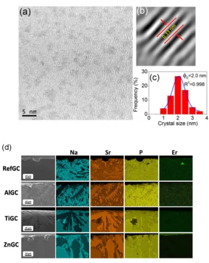
The nanostructure of the PCGs can be obtained using transmission electron microscopy (TEM) and its high-resolution analogue (HRTEM), as it is demonstrated in [105–108]. In particular, HRTEM can be used to reveal the lattice planes and the crystal-size distribution. An example of such analysis is shown in Figure 1a–c. Scanning electron microscopy (SEM) is also commonly used to image the surface of the PCGs from nano- to micrometre scale depending on the size of the crystallites and the resolution of the instrument. SEM can also provide information about the composition of the nanophase when combined with energy dispersive X-ray spectroscopy accessory (EDX) [17,109–112]. An example of combined a SEM/EDX analysis is shown in Figure 1d.
Figure 1. (a) High resolution transmission electron microscopy (HRTEM) micrograph, (b) lattice distance,
and (c) crystal-size distribution of 80SiO2–20LaF3 0.5Er3+ thin film treated at 550 °C for 1 min. Reproduced from [113], G. Gorni, J. Velázquez, J. Mosa, et al. “Transparent Sol-Gel Oxyfluoride Glass-Ceramics with High Crystalline Fraction and Study of RE Incorporation”, Nanomaterials 2019, 9, 530, CC BY 4.0. (d) FE-SEM images and energy dispersive spectroscopy (EDS) mapping of the cross-section of the GCs with compositions [0.25Er2O3−(0.5P2O5−0.4SrO−0.1Na2O)100-x−(TiO2/Al2O3/ZnO)x], x = 0 or 1.5. Reproduced from [112], P. Lopez-Iscoa, T. Salminen, T. Hakkarainen, et al. “Effect of Partial Crystallization on the Structural and Luminescence Properties of Er3+-Doped Phosphate Glasses”, Materials 2017, 10, 473, CC BY 4.0.
In the case of REE-doped materials, important information can be obtained by the use of absorption and fluorescence optical spectroscopies. Optical characterizations are very useful to discriminate the location of REE-ions as their emission and absorption spectra are strongly affected by the local environment of the REE: in the crystalline environment, the spectra consist of sharp peaks while they are broader when the REE is located in a glassy environment. Fluorescence spectroscopy can reach a sub-micron resolution if a confocal microscope is used for the measurement, allowing one to follow the changes in the optical properties between different phases in the PCGs, especially in the GCs. Similarities in the equipment needed for the Raman and photoluminescence spectroscopies make it possible to use a Raman confocal microscope to measure both the structural and the emission properties in the same area with high spatial resolution [104]. In this case, the type of signal depends on the wavelength of the excitation laser (Figure 2).
Raman spectroscopy Photoluminescence
Figure 2. Raman spectroscopy results: Distribution of different crystalline phases in sol-gel derived 30ZrO 2-70SiO2: Tb, Yb glass-ceramics obtained from analysis of the Raman spectra (λex = 532 nm): a microscopic image of the investigated area (a); distribution of tetragonal ZrO2, (b) SiO2 cristobalite, (c) and Yb2Si2O7 (d) phases. Photoluminescence results: emission intensities of Tb3+/λex = 488 nm (a), Yb3+/λex = 780 nm, (c) and relative intensities of the emission peaks calculated as I (555 nm)/I (544 nm) for Tb3+ (b), I (966 nm)/I (973 nm) for Yb3+ excited under 780 nm (d). All the spectra were obtained using a confocal Raman microscope using different excitation lasers. Adapted from [104], M. Isogai, A. Veber, M. R. Cicconi, et al. “Devitrification Behavior of Sol-Gel Derived ZrO2-SiO2 Rare-Earth Doped Glasses: Correlation between Structural and Optical Properties”, Ceramics 2018, 1, 274–286. CC BY 4.0
Special attention is paid to the determination of the nonlinear properties at 1.55 µm. In the case of the fibers, this is commonly done by the resonant optical nonlinearity measurement using a long-period fiber grating pair, initially proposed by Kim et al. [114]. The method is based on the fact that the change in the refractive index of the fiber core is related to the shift in wavelength arising from the interference between the core mode and the cladding mode of the fiber through the long-period fiber grating pair. For a more detailed description of this method, please refer to the original work [114].
The methods mentioned above have become commonly available nowadays in many laboratories. Additional characterization can be done using some more rare methods. X-ray absorption spectroscopy (XAS) can be used to determine the local environment and the redox of a specific element after a heat-treatment or in situ [113,115–118]. Small-angle neutron scattering (SANS) examines the structure of the PCGs with a characteristic scale of 1–100 nm [119–121]. Secondary ion mass spectrometry (SIMS) imaging can be used to characterize the chemical composition with high spatial resolution (60 nm). In particular, SIMS has been applied to evidence the partitioning of P, Mg, and Er elements in phase-separated nanoparticles formed in a silica-based optical fiber [122]. More recently, atom probe tomography (APT) has been employed to characterize, with a sub-nm spatial resolution, the composition of nanoparticles embedded in a glassy matrix [123].
5. Control of PCGs Transparency
One of the most important requirements when preparing transparent optical PCGs is the light scattering, including Rayleigh scattering, which should be minimized. When the size of the particles is close to the wavelength of the excitation radiation, micro-inhomogeneity occurs, leading to Mie scattering. Therefore, the size of the particles formed should be controlled. In the case of dielectric particles, the inclusions should have a refractive index similar to that of the host glass. According to Hopper [124] nanocrystals with a size <30 nm and a difference between the refraction coefficients of crystalline and glassy phases <0.3 can lead to transparent GCs.
In [125], four empirically determined requirements for ultra-transparency, as expected for optical fiber, were proposed: (i) particle size must be less than 15 nm, (ii) separation between the particles must be comparable to their size, (iii) particle size distribution must be narrow, and (iv) there must be no clustering of particles. Tick suggested that the transmission loss could be, also, minimized of the order of tens of decibels per kilometre by removing all the impurities. Later, Tick et al. demonstrated that the increase in the losses after heat treatment of fiber could be related to the different particle size distribution in the fibers and not to the mean particle size [126].
All these considerations on the characteristics of the nanoparticles aim to design a “transparent” fiber laser or amplifier; i.e., where nanoparticles would have a negligible impact on light scattering. However, light propagation in highly scattering media is a very active research area, leading to tailored light propagation in such media. For instance, by using a spatial light modulator (SLM) to shape the wavefront of the incident beam, light transmitted through a scattering medium can be focused at the output [127] or focused inside the scattering medium [128]. This approach opens new opportunities to promote nanoparticles-doped optical fiber lasers or amplifiers but necessitates one to use free space components such as SLMs which may impede their applications.
Scatterers can also be intentionally embedded in the fiber core to manage light properties during its propagation. For instance, the random fiber laser is a well-known example of photonic devices based on disordered-induced light scattering developed during the last decade. A random laser is a mirrorless laser where the properties of the light generated are defined by random multiple scattering of photons in the
optical gain medium. Various configurations have been investigated, such as the dispersion of TiO2
particles in a rhodamine 6G solution [129] or of polyhedral oligomeric silsesquioxanes nanoparticles and laser dye pyrromethene 597 in carbon disulphide [130], injected in the hollow core of a photonic crystal. In conventional telecommunications fiber, the intrinsic disorder (density and refractive index heterogeneities) has been exploited [131]. For a recent review on random fiber lasers, one can read [132]. When the size of the scatterers is about the wavelength, the light can be trapped between these randomly disordered heterogeneities through the Anderson localization mechanism [133]. If the transverse random distribution is longitudinally invariant along the fiber, the light can be guided through the transverse Anderson localization [134]. In such fiber, there is no core-cladding structure. As any location across the transverse section of the fiber guides the light, it can be used to transport an image [135]. One of the main issues related to this class of fiber relies on the ability to prepare long fiber length with invariant transverse random distribution. Several approaches are under investigation and reviewed in this paper [136].
6. Fiber Fabrication Methods
Most of the PCG fibers are drawn using the rod-in-tube technique [137]. In this technique, the prepared bulk glass is first made into a cylindrical rod through cold working and inserted into a prepared hollow glass tube with a sealed bottom to form a preform. Usually, clad and core glasses have similar compositions and the fiber is drawn near the core glass softening temperature. The use of bulk glasses for the preform preparation ensures tremendous versatility in the chemical composition of the fibers. Nevertheless, contamination on the surface of fiber core and cladding and residual surface defects can restrain its
practicability. Moreover, the softening temperature of the core glass is typically higher than its crystallization temperature, making it hard to control the crystallization process during the drawing step, which may result in the growth of large crystals and so in high transmission losses.
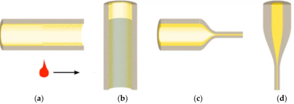
The preform can be, also, obtained by the modified chemical vapor deposition (MCVD) technique (see Figure 3), which is the most common process used to prepare special optical fibers in industry. First described by MacChesney et al. from AT&T Bell Laboratories [138], the method is based on the successive deposition of vitreous layers inside a silica glass tube (Figure 3). The chemical composition of the layers
can be controlled by use of different reactive gases (mainly SiCl4, GeCl4, and POCl3 and a fluorine carrier,
such as C2F6, SF6, or SiF4), which are carried in the tube by oxygen. However, due to the absence of volatile
precursors for many elements, the “pure” MCVD technique is mostly used for the fabrication of passive high-silica fibers with common dopants, such as Ge, P, B, and F [139]. Alternatively, the solution doping method can be used to introduce additive elements, among which are rare-earth elements, aluminium, and other modifiers [140]. In this method a porous silica layer, which is formed by MCVD at relatively low temperature, is soaked with a solution (alcoholic or aqueous) of salts of metal chlorides (ErCl3, AlCl3, etc.).
When the solution is removed, the porous layer is first dried, and, after, densified and vitrified at a high temperature (up to 1800 °C). It is also possible to introduce a crystalline phase during the doping step, e.g., using a “slurry doping method,” which is similar to the solution doping technique [141]. After, during so-called collapse step (at a temperature above 2000 °C), the tube is closed and a preform ready for the fiber drawing is obtained.
(a) (b) (c) (d)
Figure 3. Principle of the preparation of the rare-earth-doped fiber by MCVD and solution doping method:
(a) deposition, (b) solution doping, (c) collapsing, and (d) fiber drawing. Adapted with permission from [142], W. Blanc and B. Dussardier “Formation and applications of nanoparticles in silica optical fibers”, J.
Opt. 2016, 45, 247–254. Copyright 2015 The Optical Society of India.
The particle formation in the glass can be done before, after, or during the fiber drawing step, which is mostly dictated by the composition, type of the end-fiber, and particles to be stabilized. The optical preform is drawn into a fiber on a draw tower at the temperatures above the softening temperature of the glass, which is typically associated with high temperatures; e.g., around 2000 °C for high-silica glasses.
The additional heat-treatment steps, such as drawing (also vitrification and collapsing in the case of MCVD process), can change, drastically, the properties of a PCG: high temperature can lead to devitrification/demixing of the glass, transformation of the crystalline phases, and corrosion or dissolution of the particles. It can also affect the particles’ sizes and shapes. Therefore, in many cases, to avoid these uncontrollable effects, it is preferable and easier to perform an additional heat-treatment step after the drawing of a glass fiber. However, even this additional step can reduce the mechanical strength of the fiber, if surface or too-extensive a crystallization is induced.
To ensure the formation of glass (not PCG) during the drawing, the fiber can be obtained directly from a melt. This can be done using the double crucible technique. The optical fiber is fabricated by melting the core and cladding materials in two joint concentric crucibles and the fiber is drawn from the combined
melted glass. As shown in Figure 4, the core and cladding glasses are melted in the inner and outer crucibles, respectively. A somewhat intermediate method, which shares some resemblance with the rod in tube and double crucible methods is the melt-in-tube technique. Instead of using clad and core glasses of similar compositions, it is possible to use a combination of glasses. At the drawing temperature, the core is molten, whereas the clad glass is only softened [143], allowing one to avoid the undesirable crystallization of the fiber core glass. The duration of the heat treatment of the glass fiber also needs to be optimized to avoid the distortion of the fiber during the heat treatment.
(a) (b)
Figure 4. Principle (a) double-crucible techniques and (b) melt in tube techniques. Adapted with permission
from [142], W. Blanc and B. Dussardier “Formation and applications of nanoparticles in silica optical fibers”,
J. Opt. 2016, 45, 247–254. Copyright 2015 The Optical Society of India.
Since the light in the traditional core-clad fiber propagates mostly along the core, it is not sensitive to the environment of the fiber itself. Therefore, for sensing applications, it is necessary to form the MeNPs not in the bulk, but on the surface of the fiber. If no relevant charge compensation is provided under the heat-treatment of the glass the MeNPs can precipitate at the surface [144]; i.e., a standard post-annealing is capable of producing MeNPs at the surface. However, for better control of the precipitated MeNPs usually, the particles can be deposited at the surface separately. This can be done chemically. In this case, the glass surface is dipped into a solution with pre-synthesized MeNPs for the formation of a self-assembled monolayer of MeNPs on the surface [145–147]. Using this approach, it is not only possible to deposit MeNPs on the outer surfaces, but also to form layers of selected MeNPs inside the channels of microstructured optical fibers [146]. The MeNPs can be also obtained by the sputtering technique: first, a Me nano-layer is formed on the glass surface; then a subsequent annealing allows one to transform the layer into nano-particles and nano-islands [148], whereas the size of the MeNPs depends on the thickness of the initial Me-layer and the subsequent heat-treatment procedure.
7. Advances in the Fabrication of PCG Fibers
7.1. Glass-Ceramics Fibers
One of the first GC fibers was successfully obtained by Zheng, Hu, and Mackenzie in Bi–Ca–Sr–Cu–O system [149,150]. Slight modification of the glass properties by co-coping with Al or V decreased the crystallization tendency, whereas the drawing from a glass preform at the temperature above the crystallization temperature allowed the authors to avoid full devitrification of the materials during this
step. The devitrification occurring during the drawing led to precipitation of only very fine particles inside
the fibers, whereas a large number of spherical Bi2(Sr, Ca)2CuOx crystals with an average size of 0.5 µm
formed on the surface of the fibers [150]. These crystals did not affect the fiber drawing process. The final
ceramization was done by heat-treatment of the fibers. Heat treatment of the Al-containing fiber at 825 °C
for 12 h in air atmosphere led to the formation of the Bi4Ca3Sr3Cu4Oy crystals.
For optical applications, silicate GCs are the most popular among GC materials due to their unique thermo-mechanical properties, such as very low thermal expansion coefficients, combined with outstanding optical characteristics, as it is possible to stabilize small enough nanocrystals and in this way avoid the light scattering and achieve high optical transmission even in the UV-blue region. Examples of typical crystals formed in silicate glasses can be found in [71]. The first report on an GC silicate fiber laser
was reported in 2001 by Samson et al. [151]. Using the double-crucible and rod-in-tube techniques, NdF3
-doped GC fiber laser within the SiO2–AlO3/2–CdF2–PbF2–YF3–ZnF2 system was successfully prepared. It
was possible to obtain the Nd-doped fluoride crystals in the core of the single-mode optical fiber by its heat-treating at 450 °C for 30 min. The presence of the Nd-doped crystals in the fiber compromised the efficiency of the GC fibers. Such GC fibers could be obtained with low scattering losses as the crystal size
was ~10 nm. The work was then focused on transition-metal-doped GC fibers and especially on Cr4+-doped
forsterite nanocrystalline fiber which displayed luminescence similar to that of a single crystal [152]. This
GC combines the radiative properties of Cr4+-doped crystals with the advantages of glasses. Later, Samson
et al. developed novel Ni2+-doped nanocrystalline GC fibers within the SiO2–Ga2O3–Al2O3–K2O–Na2O–Li2O
system [153]. The preform was obtained using the rod-in-tube method. Heat treatment of the glass fiber at 850 °C for 2 h led to the precipitation of gallate-rich aluminogallate spinel crystals homogeneously
dispersed in the silicate glass matrix. In 2015, Ni2+ doped GC fiber was successfully prepared using the
melt-in-tube method [143]. The temperature of 1830 °C was used to fabricate the fiber; the core glass melted while the clad glass was softened. No signs of element inter-diffusion or crystallization were found in the
as-drawn glass fibers and the GC fiber was obtained by heat-treating the glass fibers; LiGa5O8 crystals were
found to precipitate in the fiber using a heat treatment at 800 °C for 10 h.
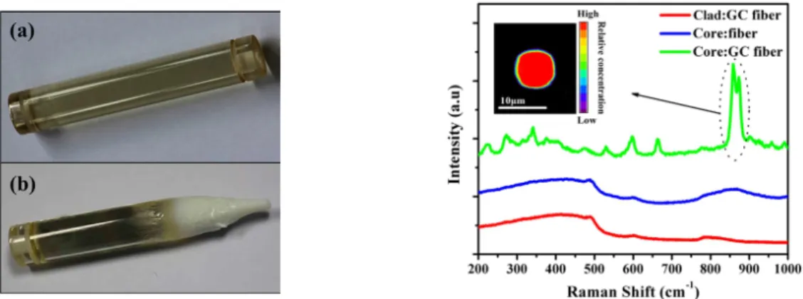
The melt-in-tube method was used recently to prepare GC optical fiber containing Ba2TiSi2O8 crystals
as the fabrication of such GC fiber using other techniques is challenging [154]. The authors noted that it was impossible to draw the fiber using the rod-in-tube technique due to the high crystallization rate of the
materials (see Figure 5, left panel). In the case of the amorphous fiber, Ba2TiSi2O8 nanocrystals could
precipitate in the fiber core evenly with a diameter between 1.0 and 6.0 nm to ensure low transmission loss using a heat treatment at a temperature of about 850 °C for 5 h (see Figure 5, right panel). These studies clearly show that the melt-in-tube fabrication method is a promising new process to obtain GC fibers, which cannot be fabricated using the conventional rod-in-tube method.
Yb-doped GC fiber was also successfully drawn from yttria–alumina–silica GC preform prepared using MCVD [118]. The collapsing step led to the formation of a phase-separated glass with two regions of different compositions. A heat treatment above 1300 °C led to the precipitation of nano-sized particles of
YbPO4, which were evidenced by X-ray absorption spectroscopy and by the shape of the emission band
which was typical of a structurally ordered phase.
Sakamoto and Yamamoto demonstrated that for Li2O–Al2O–SiO2 it is possible to draw the fibers using
pre-crystallized preforms [155]. In this work, it was shown that the drawing step could change the crystalline phase (from β-spodumene to β-quartz) and could reduce the crystallinity. Nevertheless, under optimized parameters, it was possible to get a GC fiber of good quality with a high amount of the crystalline phase.
Figure 5. Left panel: Images of the 45SiO2-5Al2O3-35BaO-15TiO2 glass preform (a) before and (b) after the drawing process using the rod-in-tube technique. Right panel: micro-Raman spectra of the precursor and GC fibers at different regions; the inset is the mapping pattern at the cross-section of GC fiber. Adapted from [154], Z. Fang, X. Xiao, X. Wang, et al. “Glass-ceramic optical fiber containing Ba2TiSi2O8 nanocrystals for frequency conversion of lasers”, Sci. Rep. 2017, 7, 44456. CC BY 4.0
Despite many successes for the silica glass, REEs do not incorporate well into the silicate glass structure. The low solubility of REE in silica glass directly results in a high probability of phase aggregation and even crystallization [156]. Clusters give rise to luminescence quenching at REE concentrations greater than 100 ppm [157]. Silica glass has relatively high phonon energy that increases the probability of non-radiative relaxation of the luminescent ions. As a consequence, this may decrease the emission quantum yield of certain optical transitions [158]. Then, several glasses were developed over time [159], such as, chalcogenides [160] and fluorides [161] which exhibit improved REE solubility and lower phonon energy. However, these glasses are prone to crystallization during the fiber making process. Additionally, they are not as compatible as silicates with the current common optical fiber cable network. In this context, oxyfluoride GC fibers have been also of great interest for the development of efficient amplifiers or lasers in glass-ceramics, as the fluoride environment is beneficial for the rare-earth ions keeping the chemical and thermal stability and the good mechanical properties of the oxide matrix [162]. The first oxyfluoride GC in
bulk form having high transparency was reported for the composition 30SiO2-15AlO1.5-24PbF2-20CdF2
-10YbF3-1ErF3. This GC was found to possess efficient up-conversion, which was up to several orders higher
when compared to the mother fluoride [9]. Since then, there has been much interest in developing novel transparent oxyfluoride glass-ceramics containing REE-doped fluoride crystals. Reviews on transparent oxyfluoride GCs in bulk form can be found in [163] and [108]. Some of the first transparent oxyfluoride GC
fibers were with the composition of 48SiO2-11Al2O3-7Na2CO3-10CaO-10PbO-11PbF2-3ErF3 and 48SiO2
-11Al2O3-7Na2CO3-10CaO-10PbO-10PbF2-3YbF3-1ErF3 [105]. They were obtained by heat-treating of the
glassy fiber at 700°C for various periods of time. The transparent GCs could be obtained when using the
treatment shorter than 32 h. Transparent GCs fibers with SrF2 and LaF3 crystals possessing intense Nd3+
emission were obtained within SiO2–Al2O3–ZnO–Na2O–SrF2 and SiO2–Al2O3–ZnF2–Na2O–LaF3 systems
[164]. In this work, Reben et al. showed that the most important parameters to control during fiber drawing
were temperature and heating time during the drawing, leading to precipitation of SrF2 nanocrystals in the
core of the fiber.
Recently, transparent oxyfluoride Nd3+ doped fibers with the composition 55SiO2–20Al2O3-15Na2
O-10LaF3 GCs were successfully prepared using a single crucible method [165]. After drawing, fibers of 5–
10 cm in length were heat-treated between 620 and 680 °C for 5 to 120 h in order to precipitate Nd3+ doped
LaF3 crystals with a size of 10–20 nm. The fibers exhibit a slower crystallization rate than the parent bulk
in order to precipitate crystals with similar size and similar crystal fraction. After, the GC fibers were
covered with SiO2 cladding using the sol-gel method. In this way, a multimode fiber with losses of about
20 dB/m at 633 nm at the doping level of 0.1% NdF3 was obtained.
Ytterbium-doped oxyfluoride GC fibers were also obtained within the SiO2-Al2O3-CdF2-PbF2-YF3 [166].
It was shown that partial devitrification of the glass occurs during the conventional glass preform drawing process. Alternatively, the glass fiber could be obtained directly from the melt, whereas the crystallization was done by an additional controlled heat-treatment step. The latter approach was found to be preferable to produce transparent GCs with nanocrystals homogeneously distributed along the fiber, as the drawing of a GC preform did not allow fine tailoring of the crystals’ sizes, shapes, and distribution along the fiber. Pb1-x-y-zCdxYyYbzF2 (x + y + z ≈ 0.3–0.4) nanocrystals with an average size of ~10 nm were found to precipitate
in the fiber heat-treated at 460 °C for 20 h, increasing the photoluminescence quantum yield in the near-infrared region compared with the glass-fiber.
GCs oxyfluoride fibers with remarkably enhanced Er3+ 2.7 µm emission under 980 nm excitation were
first reported in [167]. The fibers with the core composition 40B2O3-25SiO2-18Na2O-7NaF-10YF3-2ErF3 were
obtained using melt in tube technique. Heat treatment at 470–500 °C for 5 h led to precipitation of NaYF4:
Er3+ nanocrystals in the core. The increase in the transmission loss values at 1310 nm from 7.44 to 11.81
dB/m after heat treatment was related to the scattering caused by the precipitated nanocrystals.
Efforts have been also focused on the preparation of GCs transparent up to 12 µm using chalcogenide glasses. The crystallization of chalcogenide glasses has been of great interest [168–174]. However, the crystallization of these glasses is difficult to control, as reported in [173]; Zhang et al. reported that, as for oxide glasses, the control of the nucleation and crystal growth is very sensitive to temperature and to the glass composition. The temperature of the heat treatment should not be too high so the crystal growth can be controlled. If not controlled, the GC loses its transparency. A reasonable nucleation rate was obtained by varying the duration of the treatment, which could last for up to 15 days in order to observe a significant decrease of the expansion coefficient of the final glass-ceramics. In [175], Zhang et al. reported that it is
possible to draw the GC with the composition Ga5Sb10Ge25Se60 into infrared transmitting GC fibers. During
the fiber drawing, they noticed that the crystals in the GCs continue to grow. Although the scattering losses in short wavelengths increased, the transmission of the GC fibers beyond 6 µm remained unchanged despite the growth of the crystals during the fiber drawing.
The other technique developed to control the rare-earth optical response independently of the host glass composition involves the incorporation of rare-earth-doped nanoparticles in a glass. This new nanoparticle doping MCVD-process was implemented to fabricate REE-doped fibers. Use of erbium-doped
nanoparticles allows one to control better Er3+ local environment, decreasing the probability of the
pair-formation and up-conversion level, providing longer luminescence lifetimes; achieving high homogeneity of the dopant along the fiber length erbium-doped fibers; and reducing light attenuation level in the fiber [176–179]. This approach also works for other REEs [179,180]. Fibers have been prepared by adding other
NPs, such as REE-doped Y3Al5O12 (YAG) [181] and LaF3 [182,183] nanocrystals. These nanocrystals, used
as precursors, allow one to improve the REE luminescence properties. However, direct proof of the existence of the initial nanocrystals in the final fiber is rarely presented. In the case of LaF3 nanoparticles, it
has been clearly demonstrated that the integrity of these nanocrystals is not maintained during the MCVD
process [183]. Fluor ions react with silicon and form the gaseous SiF4 compound. Even if the nanoparticles
could be imaged in the fiber, their composition was La-silicate, not LaF3. Summary information about
various nanoparticles suitable host material composition and their characteristics can be found in [184].
7.2. Phase-Separated Fibers
Fabrication of phase-separated fibers is a quite novel area, still having a lot of things to discover. Advances in this area were achieved by the group of W. Blanc. During the fabrication of the silica core
using the MCVD process, the sintering of the soaked porous core layer, the collapsing of the tube, and the preform drawing steps require many thermal cycles with temperatures up to more than 2000 °C. These thermal cycles last for only a few seconds to a few minutes at each pass or step at specific point of the fiber. Nevertheless, due to this thermal treatment, inherent to the MCVD process, nanoparticles can be formed
in situ through the phase separation mechanism by introducing, through the doping solution, alkaline earth
elements, such as magnesium [185], calcium [186], or scandium and yttrium ions [187], resulting in the particles of nm-range size. Later, phase separation was obtained for Mg and La-doped silicate fibers [188,189]. The small size of the nanoparticles allows one to ensure low scattering losses, and at the same
time, a significant broadening of the Er3+ emission spectrum was observed (Figure 6a). It is important to
note, that the formation of the nanoparticles in these works did not require additional post-heat treatment of the fibers as the nanoparticles formed during the collapsing step of the MCVD process [190]. The particles survive the high-temperature drawing process. However, from the geometrical considerations, it is clear that their shape should evolve. Recently, to shed more light on this question, Vermillac et al. studied the morphologies of oxide particles in optical fibers [191,192]. It was found that during the drawing step, the spherical particles present in the preform could be elongated and even broken up into smaller particles (Figure 6b). The break-up phenomenon can be favoured by decreasing the drawing temperature (increasing drawing tension). This top-down approach (starting from “big” particles in the preform and finishing with “small” nanoparticles in the fiber) opens a new strategy to control the final size of the nanoparticles in the fibers.
(a) (b)
Figure 6. (a) Normalized Er3+ emission spectra of magnesium-doped phase-separated optical fibers. Different lines correspond to samples with various Mg-content ranging from 0.23 to 2.7 atom %; the violet line (the narrowest spectrum) corresponds to the reference fiber without Mg. (b) SEM images of the core of the La-doped sample containing 1 atom % of La. The core section corresponds to the longitudinal view (along the drawing axis). Reproduce from [189], M. Vermillac, J.-F. Lupi, S. Trzesien, et al. “On the Enlargement of the Emission Spectra from the 4I13/2 Level of Er3+ in Silica-Based Optical Fibers through Lanthanum or Magnesium Co-Doping”, Ceramics 2018, 1, 364–374. CC BY 4.0
The size control of nanophases in fibers provides a great opportunity for new applications. One of the most trivial examples is the development of the light-diffusing fibers used for illumination [193]. In these fibers, the scatterers (which can be air bubbles with a typical size of 50–500 nm) are located in a ring around the fiber core. Despite the apparent simplicity of this approach, one of the main issues relies on the ability to keep the scattered light intensity constant all along the fiber [194]. Sensors were recently developed, based on the enhanced nanoparticle-induced backscattered light and the optical backscatter reflectometry. The fabrication method for these sensors is simplified since there is no need for inscribing reflective
elements (such as fiber Bragg gratings) or fabricating microstructures in the fiber. A fiber-optic refractive index sensor was demonstrated by simply etching a high-scattering nanoparticle-doped fiber in hydrofluoric acid [195,196]. A setup for multiplexed distributed optical fiber sensors, which are capable to measure temperature in the range of up to 140 °C (of interest for biomedical applications such as thermo-therapy) with a spatial resolution of 2.5 mm over the several fibers simultaneously, has been reported in [197]. Finally, this approach is also applicable for strain measurements and 3D shape sensing [198,199].
7.3. MeNP-Containing Fibers
To date, most of the efforts have been focused on the fabrication of MeNP-doped silica fibers. Temperatures of about 2000 °C used for the drawing of high silica fibers are lower than the boiling point but high above the melting point of most of the metals. Therefore, MeNPs can survive, and the precipitation of the MeNPs is often performed by heat-treating the preform before the drawing; however, the drawing can change the nanoparticle characteristics dramatically. It is complicated to control the particle size and distribution, making the fabrication of the fibers with particular optical properties more challenging. Ju et al. demonstrated that the MCVD technique can be used for fabrication of Au-NP-doped silica-fibers, but, a shift of the Au-resonance absorption band was observed after the drawing when compared to the preform [200]. This shift was attributed to the recrystallization of the Au metal at high temperatures. Recently de Oliveira et al. studied different ways to produce Au-NP-doped silica fibers in detail, and mentioned that the drawing of a preform, that already has MeNPs inside (see Figure 7a), could result in the fluctuations in the NPs concentration over the length of the fiber, with the formation of regions with higher concentrations of gold clusters. These gold clusters are highly scattered and increase optical losses [201]. Several studies showed that this problem could be solved by co-doping with Al, which was found to lead to a better dispersion of Au-NPs in the final fiber and so to better optical performance [200– 202].
In the recent work of de Oliveira et al. [201] it was demonstrated that annealing of the fiber under reducing conditions results in the particles similar to the case for nanoparticles formed in the preform, allowing one to reach the concentration of the Au-NPs with resonance absorption band intensity >800 dB/m. At the same time, the fiber is fully spliceable and can be handled in a common way. Better control of
the NPs growth process can be achieved if the fiber is exposed to local heating using a CO2 laser instead of
being heat-treated in a furnace. The IR irradiation is well absorbed by silicate glasses, allowing one to locally change the temperature and to achieve resolution in the NPs nucleation regions of about 100 µm in fiber length. Changes in the laser power and in the number of scans can be used to precisely control the process of the MeNPs formation via one or two-step procedure, producing fibers with different NP concentrations and size distributions (see Figure 7b).
Despite the difficulties in the fabrication of MeNPs containing fibers, potential enhancement in the luminescence properties inspires scientists to improve the spectroscopic properties of REE-doped fibers using MeNPs. Significant efforts in the development of MeNP-doped optical fibers were performed by the
group of W.-T. Han [203–205]. In particular, it was demonstrated that co-doping of Er3+-doped
germano-silicate optical fiber with Au-NPs allowed increasing the emission intensity under 980 nm excitation about 20% [203]. Authors ascribed the observed enhancement to the absorption of hydroxyl groups by Au-NPs. However, the MeNPs co-doping also can lead to a decreased radiative emission rate; i.e., suppressing the REE luminescence [206]. The other possible reasons for this are the extensive scattering and the additional losses caused by the high MeNPs concentration [206,207].
(a) (b)
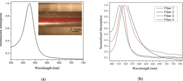
Figure 7. (a) Preform absorption spectrum after annealing and nanoparticle growth and (inset) side view of
the preform with a red-coloured core. (b) Normalized plasmon resonance absorption spectra for fibers with nanoparticles nucleated via different processes. Fiber 1: nanoparticles nucleated in the preform stage (peak at 536 nm). Fiber 2: nanoparticles nucleated in the fiber. Fiber 3: one-step nucleation with a CO2 laser (peak at 526 nm). Fiber 4: two-step nucleation with a CO2 laser (peak at 514 nm). Adapted with permission from [201], Rafael E. P. de Oliveira, Niclas Sjödin, Michael Fokine, et al. “Fabrication and Optical Characterization of Silica Optical Fibers Containing Gold Nanoparticles”, ACS Appl. Mater. Interfaces 2015, 7, 370–375. Copyright 2015 American Chemical Society.
In comparison to traditional surface sensing systems based on the plasmon resonance effect and including an optical prism in the setup, sensing configuration based on an optical fiber allows one to fabricate a small sensing element with a simplified optical design, which requires only a small sample volume and has great potential for use as disposable fiber-optic sensors and the capability for use in remote sensing [208]. For a sensor fabrication, an unclad region of the fiber can be coated with metal-layer or MeNPs. Commonly, the sensing is based on the evanescent light field absorption in the fiber, which is analogous to attenuated total reflection (ATR) spectroscopy. The sensitivity of the method depends on the length of the sensing (modified) part of the fiber [145] and the morphology of the deposited nanoparticles [209]. A LSPR-sensor based on a modified standard telecommunication single-mode fiber can achieve the sensitivity of about 10−5 RIU [210].
As an alternative to the outer surface, the MeNPs can be deposited on the inner surfaces of a microstructured fiber—the theoretical consideration of such a configuration has predicted its high sensitivity [211]. This approach was successfully realized in the work of A. Csaki et al. [146]. In this study, Ag and Au nanoparticles of different sizes and shapes were deposited inside the channels of microstructured optical fibers with high coating uniformity (see Figure 8). Experimental results agreed well with the theoretical calculations. Moreover, a proof-of-principle sensing experiment demonstrated high
Figure 8. SEM images of the inner walls of the MOFs coated with gold particles (30-nm-diameter spheres):
(a) An overview and (b) zoomed in. (c) Tilted front view of one hole’s cross-section at the starting point. (d) A view of the fiber end. (A homogeneous particle density-independent of curvature is apparent.). Reprinted with permission from [146], Andrea Csaki, Franka Jahn, Ines Latka, et al. “Nanoparticle Layer Deposition for Plasmonic Tuning of Microstructured Optical Fibers”, Small 2010, 6, 2584–2589. Copyright 2010 WILEY-VCH Verlag GmbH & Co. KGaA, Weinheim.
Nowadays NIR lasers based on different REEs dominate various practical applications. In particular, Er-doped lasers and amplifiers emitting at around 1.55 µm are used for telecommunications—the application area where the MeNP-doped fibers could be used for optical switching. It is important to note here that the enhancement of the nonlinear properties is the most pronounced for the laser wavelengths, which are in resonance with the plasmon modes of the MeNPs [212]. For the most common Au and Ag particles, the resonance band is typically observed in the visible range. The position of the resonance band can be controlled by the size of the MeNPs and the precipitation of bigger particles can shift the resonance band towards lower energies. The broader tunability range of the resonance can be achieved by an extensive control of the particles geometry and using multipolar plasmon oscillations. In particular, it was demonstrated that the resonance band in the region up to 1 µm can be achieved with a change in length of the Ag nanorods [213]. Nevertheless, even far from the resonance frequencies, e.g., at 1064 nm, nonlinear
susceptibilities of the MeNPs in colloids are in order of 10−14 ESU [212], which is about two orders higher
when compared to amorphous SiO2 at the same wavelength [214]. Therefore, the properties of the MeNPs
will determine the final nonlinear susceptibility when embedded in commonly used optical glasses, such as silica.
In practice, it was demonstrated that the formation of Au-NPs in silica glass fiber permits one to
achieve the nonlinear refractive index (n2) of about 10−16 m2/W, which is several times higher in comparison
to the reference fiber without the MeNPs [215]. To date, it has been shown that the final nonlinearity depends on the chosen metal, the concentration, and the dispersion of the NPs [202,216,217]. As was already mentioned above, co-doping with Al usually improves the dispersion of the MeNPs in the fiber and can enhance the nonlinear properties [202]. However, this is not always the case. According to Lin et al., high resonant nonlinearity in Ag-NP-doped fibers can be obtained in Al-free fibers [216]. Later, the authors demonstrated that this level of nonlinearity is enough for all-optical switching applications at 1.55 µm [217]. In more recent study on Au-NP-doped fibers it was demonstrated that a higher concentration of the nanoparticles can be achieved in the fiber, resulting in n2 = (6.75 ± 0.55) × 10−15 m2/W; i.e., five orders of

![Figure 4. Principle (a) double-crucible techniques and (b) melt in tube techniques. Adapted with permission from [142], W](https://thumb-eu.123doks.com/thumbv2/123doknet/13405498.406649/13.892.198.752.314.599/figure-principle-double-crucible-techniques-techniques-adapted-permission.webp)