HAL Id: hal-00509553
https://hal-mines-paristech.archives-ouvertes.fr/hal-00509553
Submitted on 11 Dec 2012HAL is a multi-disciplinary open access archive for the deposit and dissemination of sci-entific research documents, whether they are pub-lished or not. The documents may come from teaching and research institutions in France or abroad, or from public or private research centers.
L’archive ouverte pluridisciplinaire HAL, est destinée au dépôt et à la diffusion de documents scientifiques de niveau recherche, publiés ou non, émanant des établissements d’enseignement et de recherche français ou étrangers, des laboratoires publics ou privés.
Shear induced structuration of liquid crystalline epoxy
thermosets
Alice Mija, Patrick Navard, Christian Peiti, Dan Babor, Nathanael Guigo
To cite this version:
Alice Mija, Patrick Navard, Christian Peiti, Dan Babor, Nathanael Guigo. Shear induced structuration of liquid crystalline epoxy thermosets. European Polymer Journal, Elsevier, 2010, 46 (6), pp.Pages 1380-1387. �10.1016/j.eurpolymj.2010.04.001�. �hal-00509553�
1 Shear induced structuration of liquid crystalline epoxy thermosets
Alice Mija1*, Patrick Navard2, Christian Peiti2, Dan Babor3, Nathanael Guigo1
1
Thermokinetic Group, Laboratory of Chemistry of Organic and Metallic Materials C.M.O.M., Institute of Chemistry of Nice (CNRS FR3037), University of Nice - Sophia Antipolis, 06108
Nice Cedex 2, France
2Ecole des Mines de Paris, Centre de Mise en Forme des Matériaux, UMR CNRS/Ecole des
Mines de Paris no 7635, B.P. 207, 06904 Sophia Antipolis, France
3 “Gheorghe Asachi” Technical University, Department of Concrete Structures,
Building Materials, Technology and Management 700050 Iasi, Romania
ABSTRACT: Low-molecular weight liquid crystals (LC) have wide technological applications due to their self-assembly in the mesophase. An azomethine nematic monomer based on diglycidyl functionalized mesogenic core and without spacers has been cured with a diamine. The great affinity of LC epoxy to the formation of ordered structures introduces a spatial driving force into the process of curing. Thermal and LC behaviours were investigated by differential scanning calorimetry (DSC) and polarized optical microscopy (POM). The nature of the LC phases was confirmed by X-ray diffraction. Rheological experiments were conducted during crosslinking at different shear stresses. The viscosity of the mixture is strongly decreasing by three orders of magnitude when the solid epoxy is melting into a LC phase, and is increasing again due to the curing. Unexpected results were found. Applying a stress during curing had a profound influence on the ordering of the structure. The material becomes isotropic if a small shear stress is applied. Then, the higher the stress is, more ordered the final material is. For the highest stresses, the final material is in a highly ordered, quasi-crystalline, smectic structure.
KEYWORDS: liquid crystalline thermoset, epoxy, shear, smectic, structuration
I. Introduction
2 Liquid crystalline (LC) thermosetting resins have been under study for more than 35 years after the first suggestion by P.G. de Gennes in 19751 that crosslinking a liquid crystal could bring
some new materials. The work was pioneered by Finkelmann2, 3, 4 for LC elastomers, Carfagna5,
6, 7, 8, 9
for LC thermosets and, more recently, by Tschierske10, 11, 12 for nanoscale patterning,
mesophase engineering and new complex LC structures. A growing interest has been focused on liquid crystalline epoxy thermosets (LCETs) because of their opportunities to develop ordered, anisotropic network structure. Such opportunities consist in their applications in electronic, packaging, non-linear optics, as matrix materials for advanced composites and insulating layers.13,14 Epoxy resins with aromatic mesogens attracted much attention for preparation of LCETs because of their enhanced properties such as: anisotropic orientation, high modulus and tensile strength, low thermal and expansion coefficient and low dielectric constant.15, 16 One way to obtain LCETs is the curing reaction of some functionalized potentially mesogenic rigid molecules with a suitable curing agent. Biphenyl, naphthalene, α-methylstylbene and esters are the compounds that have been most frequently studied to obtain LCETs.17, 18, 19, 20 There is a widespread interest in the synthesis of azomethine LCETs, conjugated polymers, because of their useful electronic, optoelectronic, electrochemical, non-linear optical properties as well as of their potential applications in optical switching and information storage.21, 22, 23, 24 Azomethine LC epoxy resins have been extensively studied by Mormann and his co-workers25, 26, 27, 28, 29 who obtained LCETs by curing azomethine epoxy monomers with amines.
However, the high cross-linking density of thermosets is not very compatible with a long range ordering, and the improvement of mechanical properties is not so spectacular, especially when the LC thermoset is reinforced with fibers.30 Nevertheless, a striking effect on one specific property, fracture toughness, was seen with pure LC epoxy thermosets. An increase from a resilience of 1.3 J.cm-2 to more than 170 J.cm-2 was observed when going from an isotropic to a
3 LC epoxy.30 Such an increase was thought to be due to the polydomain texture of the LC epoxy thermoset.30, 31 Fracture is not propagating easily through the domains, due to the formation of numerous segmented unlinked microcracks. The crack path length is thus strongly increased. For conventional uncrosslinked liquid crystal (polymer or not), an external field has a profound influence on the texture organisation. Providing that the dielectric and magnetic susceptibilities have the proper anisotropies, an electric or a magnetic field is orienting a LC phase, reducing the number of orientational defects and moving the texture towards a monodomain. This also occurs with LC elastomers32 and LC thermosets33, 34 the obtained structures being frozen during the cross-linking reaction. This is increasing the tensile module and strength, and gives high fracture toughness, high ductility, low moisture absorption, outstanding chemical and solvent resistances, high Tg, unusual optical, electrical and thermal properties.31, 32, 33, 35
Another way to produce a change in the texture is to use a mechanical field, namely a flow. The use of an elongational flow during the curing of thermosets has been reported5 without specifying how it was produced and which results it was giving. Shear is known to induce complicated effects on the orientation of nematic polymer liquid crystals.5, 36, 37 It does not necessarily bring a nematic polymer in a more oriented state since it may destroy an initial monodomain and breaks it into many domains, not correlated in orientation. This is due to the so-called director tumbling that may occur at low shear rates. Only high shear rates may orient macroscopically a LC polymer. The shear of smectic polymers is a nearly unknown area.38
The aim of this work is to investigate the effect of a shear during curing of a LC epoxy thermoset. To our knowledge, shear has never been tried as a method to modify the texture of a LC thermosets during curing. This requires us to devise a way to perform the experiments and to monitor the texture after imposing a controlled shear flow. The choice of the LC thermoset was an epoxy monomer based on azomethine mesogen crosslinked with an aromatic diamine. The
4 choice of the curing agent was motivated by the relatively slow crosslinking process that allows enough time to perform the shear experiments. The epoxy monomer develops a nematic state once molten. Many systems where the liquid crystalline state is obtained during curing (i.e. starting with an isotropic system) were tested without success because of the too long time needed to thermally equilibrate the sample in the rheometer, which was not leaving enough time to shear the sample in a controlled way. The shear experiments were performed during curing at different stresses (50, 100, 200, 400, and 600 Pa). The resulting textures were observed by optical microscopy and analysed by wide angle X-ray scattering.
II. Experimental Part II.1. Materials
The epoxy monomer N, N'-bis[4-(2,3-epoxypropoxy)benzylidene]1,4-phenylenediamine, (called E1): N N HC CH O CH2 CH O O CH2 CH2 CH CH2 O
was prepared using the method described by Wheeler and Gore.39 An azomethine based bisphenol A1:
HO HC N N CH OH
is obtained from 1,4-phenylenediamine and 4-hydroxy-benzaldehyde. The E1 diglycidyl is then synthesized by the epoxydation of A1 with epichlorohydrine using tetrabutylammonium bromide as catalyst.40
A 500 mL two-necked flask with a reflux condenser was filled with 0.1 mol of bisphenol (A1), 3 mol of epichlorohydrine and 0.15 g of catalyst. The mixture was stirred at 60°C for 1 h. At 60°C
5 and 130 mbar was added dropwise 0.2 mol of a 45% wt. aqueous NaOH solution and the reaction was continued for 2 h. The sodium chloride formed was filtrated and the volatile products distillated. The final product was redistillated with toluene. IR and 1H-NMR spectra confirmed the chemical structure.41 The diepoxy monomer has a molar mass of about 428 g.mol-1 and a melting temperature of 192°C, above which it is a nematic liquid crystal.
Methylene bis-chloro-diethylaniline (MCDEA) used as curing agent was provided by Lonza and it was used without further purification.
NH2 H2N CH2 C2H5 C2H5 C2H5 C2H5 Cl Cl
MCDEA has a molar mass of 380.5 g.mol-1 and a melting temperature of 90.5°C to an isotropic liquid.
The E1/MCDEA mixtures were prepared by mixing in a stoechiometric ratio the two components in the solid powdered state. The chemical reaction takes place upon heating, in the melt, without need of an external catalyst. More details about the characterisation of the monomers and the curing process are given in reference 41.
II.2. Shear experiments protocol
Experiments were conducted in isothermal mode, at 170°C, below the melting temperature of E1 (192°C). This low temperature was chosen because it slowed down the reaction, leaving enough time to be able to shear the sample for a quite long time before the complete curing. The constraint of having a long time, and thus a low kinetics of reaction, was one of the difficulties that had to be overcome since the equilibration time of the rheometer is quite long. Shear was done in a plate-plate geometry with a StressTech rheometer from Rheologica. Two other
6 difficulties had to be overcome. First, because the epoxies are thermosets, it was difficult to perform the experiments with the normal plates. This would have brought problems for separating the plates after curing. Second, the objective is to analyse and texture of the final cured material, which had to be removed from the rheometer and studied without being destroyed. For these reasons, we choose to use disposable plates that were machined in order to have three windows as shown in Figure 1. A circular glass slide was then glued on each plate. The plate diameter was 25 mm and the gap between the two glass slides where the sample was placed as a powder was 0.4 mm.
The procedure was as follows: around 0.22 g of the solid mixture (in the form of pre-mixed E1/MCDEA powder) was placed on the bottom plate. The rheometer was closed and heated at 190°C, kept 10 s at this temperature in order to melt the powder and ensure homogeneity of the mixture. It was then cooled down to 170°C. After several seconds for equilibrating the apparatus a stress controlled shear was imposed at different stress levels (50, 100, 200, 400 and 600 Pa). A careful temperature calibration of the system was performed, since curing is very sensitive to it. As it will be shown later, the cooling resulted in a partial recrystallisation of the mixture. The shearing process was taking place until stopping. The shear stopped before the end of the curing for two reasons. At lowest stress, the mixture is first melting and then curing. At a certain curing stage, the material becomes so viscous that the shear stopped. At high stresses, another completely different reason prevents the shearing during curing. After the melting of the epoxy, the system was so fluid that the imposed large stresses lead to very high rotational velocities. The shear had to be stopped and the curing continued in the rheometer at rest.
Once the curing finished, the whole system was cooled down at 10°C.min-1 to room temperature. The two plates, glued by the epoxy curing, were removed as a single piece from the rheometer. With the plate arrangement of Figure 1, there were always in all the experiments two windows
7 facing each other, allowing optical microscopy and X-ray scattering to be performed directly without destroying the sample.
II.3. Methods
DSC measurements were performed on a Perkin-Elmer DSC-7. Temperature and enthalpy calibrations were done by using indium and zinc standards. Samples of approximately 5 mg of E1/MCDEA mixtures were placed into aluminium pans. The DSC measurements of curing have been conducted at the same heating program as in the shear experiments: heated at 190°C, kept 10 s at this temperature and then cooled down to 170°C.
The textures were observed with an optical microscope Reichert Jung in transmitted light, equipped with cross polarizers and with a hot stage Linkam, model TH 600.
Wide-angle X ray diffraction patterns were obtained from a Philips PW 1830 generator, at 45 kV and 30 mA, with a Ni filtered Cu anticathode tube. The exposure time of the Kodak DEF-5 films was about 1.5 h. The X-ray scattering was performed through the two glass slides sandwiching the sample.
III. Results and Discussions III.1. Curing without shearing
Curing of E1 with MCDEA takes place through the following sequence of reactions:
N N HC CH O CH2 CH O O CH2 CH2 CH CH2 O NH2 H2N CH2 C2H5 C2H5 C 2H5 C2H5 Cl Cl + E 1 MCDEA) ( ( )
8 ) (E1 Cl Cl C2H5 C2H5 C2H5 C2H5 CH2 NH2 O CH2 CH CH2 O HC N N CH O CH2 CH CH2 HN OH + OH N N HC CH O CH CH2 O CH2 CH2 CH CH2 CH2 C2H5 C2H5 C2H5 C2H5 Cl Cl OH OH CH2 CH CH2 O HC N N CH O CH2 CH CH2 OH N N OH CH CH2 CH2 CH OH Cl Cl C2H5 C2H5 C2H5 C2H5 CH2 N N OH OH N HC O CH2 CH2 O HC N N HC O CH2 CH2 O HC N OH OH
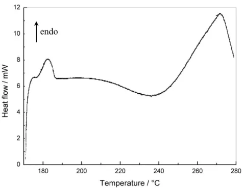
To look inside the thermal events occurring during shear experiments DSC measurements were conducted in the same temperature program. Figure 2 shows the DSC data of the E1/MCDEA mixture brought to 190°C, then cooled down to 170°C, then heated again. We can observe three distinct thermal DSC events that occur in the 170-280°C temperature range. The first event is endothermic and occurs in the 175-185°C interval. This endothermic peak was attributed to the melting of the epoxy monomer and shows that it recrystallises during above mentioned procedure. As seen in Figure 2, an exothermic DSC peak associated to the curing reaction is observed in 190-270°C temperature range. After the completion of the melting, another exothermic peak appears above 275°C. At this temperature thermal degradations can start.
The epoxy prepolymer recrystallization at 170°C depends on the real temperature cycle (for example how long the sample stays at 170°C). The cooling in the rheometer being slow, it can be easily predicted that E1 will be crystallized at the beginning of the shearing. In this case, the curing is occurring even though the temperature is below the melting temperature of the epoxy,
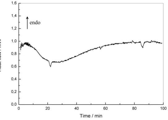
9 and a dissolution process is also seen for other epoxy compounds.41 If put in a situation where the two components are molten, by cooling down quickly from 190°C to 170°C and then recording the DSC trace, it shows a smooth curing reaction spanning over 75 min (Figure 3).
After the isothermal reaction at 170°C, the obtained textures were studied by X-ray scattering and optical microscopy. Optical microscopy (Figure 4) shows a very tight texture that is typical of a smectic structure as confirmed by the X ray pattern shown in Figure 5 with clearly visible five diffraction rings.
III.2. Reactions during shear
The original aim of this study is to examine the influence of the shear during crosslinking. As already mentioned, if the curing is performed in a region where both materials are molten, i.e. above 195°C, the reaction proceeds too quickly to be able to perform a shear in a controlled way. So, the reaction was conducted at 170°C, but in a region where E1 is recrystallized. This means that the state of the mixture is a suspension of solid E1 particles in the molten MCDEA with very high viscosity. The viscometer being stress controlled, only high stresses are able to noticeably rotate the plate. But with the dissolution of the E1 in MCDEA, the viscosity is dropping to very low values, where these high stresses are leading to high rotation speeds, ejecting the material out of the gap. We are thus forced to separate our procedure into two parts. The first one conducted at high stresses has been applied only to the dissolution process. In practice, the shear will be stopped before the beginning of the curing stage. When the lowest stress was applied, it was also possible to monitor the texture during the curing. The second is when low stresses are applied. Its effect will not be seen during dissolution (no rotation), but will be effective during the curing.
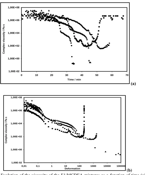
10 Figure 6 shows that the complex viscosity mixture reacts in different manner in function of the shear stress. We observed that the curing behavior could be separate in two major: one of low (50 and 200Pa) and another of high (400 and 600Pa) shear stress. Figure 6 highlighted a very high complex viscosity at the beginning of the shears ( 106 Pa.s), typically of a highly filled suspension. The viscosity drops down to very low values (10-1 Pa.s) during the dissolution, but there is no possible shearing afterwards, the rheometer having to be stopped. Only the low stresses (50 and 200Pa) show the increase of the viscosity due to the curing. Figure 6(a) shows that the viscosity is not changing much during the first 20 min of the experiments. Low stresses produce dissolution, melting and permit to develop the curing reaction. As mentioned above42 we have a complex reaction system. In the first time, we have observed a thermodynamical competition between melting of reactants and chemical reactions. As shown in Figure 2 this competition is illustrated in the allure of DSC curve by the rapid succession of endotherm (melting) and exotherm (chemical reactions). At the beginning of the process dissolution and orientation of LC phase occur, leading to a decrease of viscosity. Figure 6(b) shows that during this period of time, the viscosity is so high that a very limited deformation is applied to the sample, less than 0.1 deformation units. As soon as E1 is dissolved enough, the viscosity drops down dramatically in a few minutes, decreasing by three orders of magnitude. This allows the mixture to flow and the deformation starts to be effective. There is no doubt that this shear is inducing even more dissolution, and thus a further drop of viscosity. For the lowest stresses, since the time spent is longer, curing reactions start so the viscosity increases. This is very clear for the 50 Pa where the viscosity rose abruptly with a strong decrease of deformation. According to rheological measurements presented in Figure 6(a), further progress reaction is accompanied by some increase in the viscosity with increasing extent of reaction. Formation of growing branched
11 polymers occurs for this stage which is expressed by a quasi-exponential increase of viscosity of the medium. This increase is generally observed for the curing of thermosets before gelation. A plateau is reached after ~55 min indicating that the system is in the glassy state.
The high stresses (400 and 600 Pa) cause an important increase in molecular mobility leading to the orientation of the LC phase. This occurs at the early stages of curing and dramatically changes the reaction medium. Since the rate of a chemical reaction generally depends on the transport properties of the reaction medium, one may expect the orientation of the LC phase to significantly affect the kinetic parameters of the curing reaction. Indeed, under high shear level the curing system shows a dramatic decrease of the complex viscosity about seven orders of magnitude. The alignment of the oligomers creates an advantageous situation for their cross-linking that results in acceleration of the overall curing rate.
What can be concluded from these experiments is that for the lowest stresses, shear occurs first in the dissolution stage, and then in the curing stage. For the two highest stresses, shear occurs only during the dissolution stage and the mixture polymerise without shear.
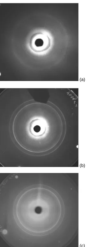
Let us come now to the interesting result, already noticed, that there is no orientation. This is quite clear on all the X-ray patterns that were obtained (Figure 7 (a-c)). In no case was a sign of orientation found. It means that the flow is not able to place all the mesogenic units at a given orientation, contrary to what is known for liquid crystalline materials and block copolymers,43 similar classes of materials. This can be due to the fact that a shear neither during dissolution and curing nor during dissolution alone enables the material to show orientation. But the flow has a strong influence on the level of order that the mesophase reaches after having been sheared. Table 1 shows that applying a low stress during the dissolution and the curing stages destroys the smectic order of the final material, while applying a high stress increases the order. At stresses of 400 and 600 Pa, the system solidifies in more ordered smectic phases. It is interesting to note that
12 there are two groups of X-ray results. The lower stress (50 and 100 Pa) destroys the smectic order phase of materials (cured without shear), while the highest stresses transform the structure strongly. The inter-mesogen distance is changed. The structure is highly ordered, with up to six clear sharp rings seen at 400 and 600 Pa, showing a quasi-crystalline structure. Such an organisation has not been seen yet with LC thermosets.
There is not so much difference between the pure E1 monomer characteristic distance (4.33 Å) and the mean intermesogen distance at rest or at low stresses (4.29 Å). But at high stresses, this distance is much smaller, down to 4.07 Å. A more compact structure is generated with the increase of ordering. An example of a texture obtained under a shear stress of 200 Pa is given in Figure 8.
What can be imagined as an explanation for these phenomena? The shear rates attained during the final stage of shearing at high stresses are very high (until about 500 s-1 at 400 Pa and 200 s-1 for 600 Pa). These high shear rates may force chain to align very well while they are dissolving in the MCDEA liquid, leading to a favourable structure for a subsequent ordering of the smectic phase. Why this is broken into small monocrystals (the peaks are very fine) remains to be studied.
IV. Conclusion
A shear imposed at the beginning of the curing of the E1/MCDEA thermoset has a profound influence on the structure and texture of the final product. The diffusion effect of the medium becomes important at the high stresses when the reacting system undergoes orientation and faster curing rates in a very ordered smectic phase.The dramatic restriction of the molecular orientation induced by the low stresses is reflected in decreasing the level of order.
One of the reasons of the very good fracture toughness resistance of LC thermosets is their polydomain structure. The fact that a shear can lead to a polydomain structure with highly
13 ordered domains can bring some advantages in the search for better composite matrices. Other types of thermosets and other types of shear (oscillatory shear could be a good candidate) must be studied to see if such shear-induced ordering is a general feature.
14 Table 1. Bragg distances of E1 or E1/MCDEA samples measured by WAXS at room
temperature.
Material Phase Bragg distance in Å
E1 nematic 6.69 4.33 E1/MCDEA without shearing cured at 180°C smectic 6.69 4.78 4.59 4.29 3.67 E1/MCDEA 50 Pa and 100 Pa cured at 170°C isotropic 6.69 E1/MCDEA 200 Pa cured at 170°C nematic 6.69 4.29 E1/MCDEA 400 Pa cured at 170°C smectic 6.69 4.59 4.43 4.07 3.62 3.03 2.94 E1/MCDEA 600 Pa cured at 170°C smectic 6.69 4.59 4.43 4.07 3.62 3.03 2.94
15 Captions for the figures
Figure 1. Schematic drawing of the experimental shear fixture.
Figure 2. DSC data of the heat release during non-isothermal curing of E1/MCDEA. Mixture annealed for 10s at 190°C, cooled to 170°C and heated between 170 - 280°C at 10°C.min-1. Figure 3. DSC data of the heat release during isothermal curing of E1/MCDEA mixture at 170°C Figure 4. Texture of E1/MCDEA thermosets cured at 170°C without shear under the depolarized microscope.
Figure 5. X-ray pattern at room temperature for the E1/MCDEA sample isothermally cured at 170°C.
Figure 6. Evolution of the viscosity of the E1/MCDEA mixtures as a function of time (a) and shear deformation (b) for the four stresses, ■50 Pa, 200 Pa, 400 Pa and
600 Pa.Figure 7. X-ray patterns of structuration of E1/MCDEA LC thermoset cured under shear at 200 (a), 400 (b) and 600 Pa (c).
16
Glass slide
Figure 1. Schematic drawing of the experimental shear fixture.
Figure 2. DSC data of the heat release during non-isothermal curing of E1/MCDEA. Mixture annealed for 10s at 190°C, cooled to 170°C and heated between 170 - 280°C at 10°C.min-1.
17 Figure 3. DSC data of the heat release during isothermal curing of E1/MCDEA mixture at 170°C
Figure 4. Texture of E1/MCDEA thermosets cured at 170°C without shear under the polarized microscope.
3 300 mm
18 Figure 5. X-ray pattern for the E1/MCDEA sample isothermally cured at 170°C.
19 1,00E-02 1,00E+00 1,00E+02 1,00E+04 1,00E+06 1,00E+08 0 10 20 30 40 50 60 70 Time / min C o m p le x v is c o s ity / Pa s (a) 1,00E-02 1,00E+00 1,00E+02 1,00E+04 1,00E+06 1,00E+08 0,01 0,1 1 10 100 1000 10000 100000 Deformation C o m p le x v is c o s ity / Pa s (b)
Figure 6. Evolution of the viscosity of the E1/MCDEA mixtures as a function of time (a) and shear deformation (b) for the four stresses, ■50 Pa, 200 Pa, 400 Pa and
600 Pa.20
(a)
(b)
(c)
Figure 7. X-ray patterns of structuration of E1/MCDEA LC thermoset cured under shear at 200 (a), 400 (b) and 600 Pa (c).
21 Figure 8. Texture of E1/MCDEA thermosets cured under shear at 170°C and 200 Pa
22
References
1 de Gennes, P.G. C.R. Acad. Sc. Paris, 1975, 281B, 101-103.
2 Finkelmann, H.; Kock, H. J.; Rehage, G. Makromolekulare Chemie, Rapid Communications,
1981, 2(4), 317-322.
3
Greve A, Finkelmann H,Macromol. Chem. Phys., 2001, 202, 2926.
4
Hiraoka K, Uematsu Y, Stein P, Finkelmann H, Macromol. Chem. Phys., 2002, 203, 2205.
5 Carfagna C, Nicolais L, Amendola E, Carfagna C. JR, Filippov AG, J. Appl. Polym. Sci. 1992,
44, 1465.
6 Carfagna C, Amendola E, Giamberini M, Filippov AG, Macromol. Chem. Phys. 1994, 195, 279. 7
Carfagna C, Amendola E, Giamberini M, Prog. Polym. Sci., 1997, 22, 1607.
8
Giamberini M, Amendola E, Carfagna C, Macromol. Rapid Commun. 1995, 16 (2), 97.
9
Frigione M, Calo`E, Maffezzoli A, Carfagna C, Malucelli G, Macromol. Chem. Phys., 2004, 205, 2175.
10
Tschierske C, Nature, 2002, 419, 681.
11
Tschierske C, Chem. Soc. Rev., 2007, 36, 1930.
12
Keith C, Dantlgraber G, Reddy RA, Baumeister U, Prehm M, Hahn H,Lang H, Tschierske C,
J. Mater. Chem., 2007, 17, 3796.
13
Barclay GG, Ober CK, Prog. Polym. Sci. 1993;18, 899.
14 Shiota A, Ober CK, Prog. Polym. Sci. 1997; 22, 975.
15 Chen M, Ren AS, Wang JF, Lee MS, Dalton LR, Zhang H, Sun E, Steiner WH, Polym. Prepr.
1999;40:162.
16 Shiota A, Ober CK, Polymer 1997;38, 5857.
17 Mititelu A, Hamaide T, Novat C., Dupuy I., Cascaval CN, Simionescu BC, Navard P.,
Macromol Chem Phys, 2000; 201, 1209.
18 Mititelu-Mija A, Cascaval CN, Navard P, Design Monom. Polym., 2005; 8, 487.
19 Barclay GG, Ober CK, Papathomas KJ, Wang DW, J Polym Sci Part A:Polym Chem, 1998,
30, 1831.
20 Szepaniak B, Frish KC, Penczek P, Leszezynska I, Cholinska M, Rudnik E, J Polym Sci Part
A:Polym Chem, 1995, 33, 1275.
21 Iwan A., Sek D.,Prog. Polym. Sci., 2008, 33, 289–345
22 Ribera D, Montecón A, Serra A, Macromol. Chem. Phys.; 2001, 202, 1658. 23 Choi E-J, Ahn H-K, Lee JK, Jin J-II, Polymer, 2000, 41, 7617.
24 Castell P, Galiá M, Serra A, Macromol. Chem. Phys.; 2001, 202, 1649. 25
Mormann W, Zimmermann JG, Macromolecules, 1996, 29, 1105.
26 Mormann W, Bröcher M, Polymer, 1998, 40, 193.
27 Mormann W, Bröcher M, Macromol. Chem. Phys.; 1998, 199, 1935.
28 Mormann W, Bröcher M, Schwarz M, Macromol. Chem. Phys.; 1997; 198, 3615. 29 Mormann W, Pokropski T, Macromol. Mater. Eng., 2005, 290, 891.
30 Carfagna, C.; Meo, G.; Nicolais, L.; Giamberini, M.; Priola, A.; Malucelli, G. Macromol.
Chem. Phys., 2000, 201, 2639.
31 Sue, H. J.; Earls, J. D.; Hefner Jr., R. E. J. Mater. Sci., 1997, 32, 4031.
23
33 Barclay GG, Ober CK; Papathomas KI; Wang DW. J. Polym. Sci.(A), 1992, 30,1831.
34 Barclay GG, McNamee SG; Ober CK; Papathomas KI; Wang D.W. J. Polym. Sci. (A), 1992,
30, 1845.
35 Giamberini M, Cerruti P, Ambrogi V, Vestito C, Covino F, Carfagna C.Polymer, 2005, 46
9113.
36 Larson, R.G. Macromolecules, 1989, 23, 3983.
37 Marrucci G.; Maffetone, P.L.Macromolecules, 1989, 22, 4076. 38 James SG; Navard P; Noel C. Rheol. Acta, 1990, 29, 366
.
39 Wheeler OH; Gore PH. J. Org. Chem., 1961, 26, 3298. 40 Mikroyannidis J. Polymer Internationnal, 1995, 25, 91.
41 Mititelu A. Résines époxydes mésomorphes, thèse de doctorat, Ecole des Mines de
Paris/Universitatea Tehnica ''Gh. Asachi'' Iasi, 2001.
42 Vyazovkin S, Mititelu A, Sbirrazzuoli N, Macromol. Rapid Commun. 2003, 24, 1060.
43 de Moel K.; Maki-Ontto R.; Stamn M.; Ikkala O.; ten Brinke G. Macromolecules, 2001, 34,