HAL Id: hal-00784289
https://hal.archives-ouvertes.fr/hal-00784289
Submitted on 4 Feb 2013
HAL is a multi-disciplinary open access
archive for the deposit and dissemination of sci-entific research documents, whether they are pub-lished or not. The documents may come from teaching and research institutions in France or abroad, or from public or private research centers.
L’archive ouverte pluridisciplinaire HAL, est destinée au dépôt et à la diffusion de documents scientifiques de niveau recherche, publiés ou non, émanant des établissements d’enseignement et de recherche français ou étrangers, des laboratoires publics ou privés.
Nizar Aouina, F. Balbaud-Célérier, François Huet, Suzanne Joiret, Hubert
Perrot, F. Rouillard, Vincent Vivier
To cite this version:
Nizar Aouina, F. Balbaud-Célérier, François Huet, Suzanne Joiret, Hubert Perrot, et al.. A flow microdevice for studying the initiation and propagation of a single pit. Corrosion Science, Elsevier, 2012, 62, pp.1-4. �10.1016/j.corsci.2012.05.002�. �hal-00784289�
1
A flow microdevice for studying the initiation
and propagation of a single pit
N. Aouinaa,b, F. Balbaud-Célérierc, F. Hueta,b, S. Joireta,b, H. Perrota,b, F. Rouillardc,*, V. Viviera,b,*
a CNRS, UPR15, Laboratoire Interfaces et Systèmes Electrochimiques, F-75005 Paris, France b
UPMC Univ Paris 06, UPR15, LISE, 4 place Jussieu, F-75005 Paris, France
c
CEA/DEN/DANS/DPC/SCCME/LECNA, 91191 Gif sur Yvette, France
Abstract
A novel experimental setup in which a glass microcapillary can be precisely positioned close to a metallic electrode has been developed to locally inject aggressive solutions at will. It has been used for studying the pitting corrosion of a 316L stainless steel in 0.5 M H2SO4 medium.
The amount of chloride ions released by the capillary could be controlled and the analysis of the corrosion products by scanning electron microscopy and energy dispersive X-ray spectroscopy showed there was no selective dissolution of the 316L stainless steel. This device was shown to be an efficient tool for understanding localized corrosion.
*Corresponding authors.
V. Vivier Tel.: +33-1-44274158; fax: 33-1-44274074 E-mail address: [email protected]
F. Rouillard Tel.: +33-1-69081614; fax: 33-1-69081586 E-mail address: [email protected]
2 1. Introduction
Pitting corrosion has been in the focus for many decades of research providing valuable information on the mechanisms, the shapes of growing pits, and the relationships linking various parameters such as temperature, pH and potential to the corrosion rate. Most of these researches were carried out directly in chloride ions containing solutions, giving rise to several pits on the metal surface. Research groups involved in stainless steel (SS) investigations distinguished three phases in the development of a pit, namely nucleation, metastable growth and stable growth. Most of the pits last no longer than a few seconds and never reach a stable phase [1-4]. Some authors have described the stable phase as a diffusion controlled dissolution process, totally independent of the polarization potential, which proceeds through the formation of a high electrical resistant, saturated metal salt film in the bottom of the pit [5-8]. The presence of the film decreases the dissolution rate, changing the rate limiting process from an activation controlled process at the metal-electrolyte interface to a diffusion controlled process in the electrolyte. In case of a partially covered or sufficiently deep pit, the salt film could withstand dissolution to keep the pit active [9, 10]. According to Pistorius and Burstein [11, 12], stable pits generated on 304 SS in 1 M NaCl + 0.1 M H2SO4
(pH = 0.7) have a pit stability factor x i (where x is the pit depth and i is the pit current density) of 3.2 ± 0.2 mA cm-1. Open hemispherical pits having generally an x i factor lower than 3.2 mA cm-1 are prone to rapid repassivation.
One of the main drawbacks of the experimental approach described above is that data collected by means of global electrochemical techniques correspond to the overall surface of the sample rather than to the local behaviour of individual pits. Attempts to correlate the corrosion current to the evolution of a particular pit were limited by the complexity and variability of the collected data. Recently, focus has been laid on the generation of a single pit at a preselected site of the electrode surface in order to avoid the occurrence of random pits
3 anywhere on the electrode surface and to allow a single event to be observed from its birth to its death. For instance, Vuillemin et al. [13] used a microcapillary to inject 250 nL of an aggressive solution of HCl, NaCl or H2SO4 over a predefined single MnS inclusion on 316L
SS. Subsequently, the scanning vibrating electrode technique (SVET) was used for monitoring the local current flow due to corrosion of the activated MnS inclusion. It was shown that a single pit could only be initiated using HCl, whereas H2SO4 partially dissolved
the inclusion. Other groups have used a scanning electrochemical microscope (SECM) to initiate single pits either on iron [14-16] or on SS [17]. In that case, the SECM tip was used to release chloride ions close to the metallic substrate by reducing either trichloroacetic acid [16] or AgCl deposits on the tip [14, 15]. On iron, the formation of a local aggressive chemical environment after the chloride ions release leads to the initiation of a single pit that propagates differently, depending on the solution pH. In basic solutions, the pit seemed to last indefinitely whereas in sulfuric acid solutions, it remained active for a short period before the pitting current suddenly decreased, suggesting that chloride ions were consumed along with iron dissolution[15, 18]. On SS [17], the initiation of a single pit required a higher amount of chloride ions than for pure iron in 0.5 M H2SO4, especially at high noble potential in the
passive domain where the passive layer is thicker. Whatever the substrate potential, all the single pits remained active only for few minutes. Sustaining the pit activity by adding chloride ions into the probe-substrate thin layer was technically unfeasible because of the limited amount of chloride ions available with an Ag/AgCl probe.
In this work, the Ag probe was substituted by a glass microcapillary, positioned close to the electrode surface, in which chloride ions were injected at will from a syringe pump. Maintaining the chloride ions supply makes the study more relevant to describe atmospheric corrosion where pollutants such as chlorides and SO2 ceaselessly cross the gas-to-liquid
4 capillary above the metal, which enables initiating the single pit systematically at the electrode center, is described.
2. Experimental
2.1 Instrumentation
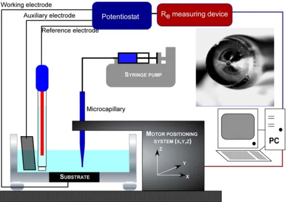
The glass microcapillary positioning was performed using the SECM setup sketched in Fig. 1. It consisted in a lab-made potentiostat and a 3-axis positioning system (VP-25XA, Newport) driven by a 100 nm spatial-resolution motion encoder (ESP300, Newport). The entire setup was controlled by a software developed under Labview®. The precise positioning of the capillary was performed by measuring the electrolyte resistance, Re, between the substrate and the reference electrode (RE) [19, 20]. This technique was shown to be sensitive enough to monitor the position of an insulating material (a small glass sphere) in the close vicinity of the substrate [21]. Briefly, a function generator (TG550, TTi) was used to superimpose a sinusoidal voltage at high frequency (fHF = 100 kHz; peak-to-peak amplitude
Vp-p of 10-50 mV) to the dc-potential of the substrate. The current flowing to the substrate was
sent to a home-made analogue device that delivers a voltage signal, VRe, proportional to the amplitude of the ac-current and, therefore, to the reciprocal of the electrolyte resistance, 1/Re. Following the Re variation by this way allowed the capillary tip to be precisely positioned above the center of the disk substrate without adding any redox mediator in the electrode. This technique was already used in a previous work to position the SECM probe above the electrode center but in the present work the glass microcapillary was an insulator so that Re was measured between the substrate and the RE instead of between the SECM probe and the RE.
5 The electrochemical investigations were performed using a conventional three-electrode electrochemical cell with a 316L SS disk of 0.2 cm2 surface area as working electrode. The nominal composition of the SS was obtained by averaging energy dispersive X-ray spectroscopy (EDAX) values measured at various locations: Fe (66.9 at.%), Cr (18.9 at.%), Ni (11.5 at.%), Mo (1.8 at.%), and Si (0.9 at.%). The disk was ground with 1200, 2400, and 4000 SiC abrasive paper, and then cleaned with a mixture of water/ethanol in an ultrasonic bath for 5 min prior to be used as the substrate material. A 6 cm2 surface area platinum grid acted as the counter electrode. A Mercury Sulfate reference Electrode (MSE) saturated in potassium sulfate was used and all potentials were referred to this electrode. All experiments were performed in a 0.5 M H2SO4 solution. The input of the glass capillary was
connected to a 100 L Hamilton® syringe filled with a 2 M NaCl + 0.5 M H
2SO4 solution. A
KD Scientific® syringe driver was used to gradually push the syringe piston with a release rate of 10 L/h. The glass capillary shown in the inset of Fig. 1 had a 100 m inner diameter and a 900 m outer diameter produced with a micropipette puller (Sutter P2000). Since the smaller the inner diameter of the tube, the greater the flux of injected solution, no soluble corrosion products could diffuse into the 100 m inner diameter capillary, as observed when testing capillaries with 250 m and 150 m inner diameters (not shown here).
2.3 Physical characterization
All pits were characterized ex-situ with a Leica Stereoscan 440 scanning electron microscope (SEM) coupled to an EDAX analysis. The pit depth was measured using a differential focusing technique with an optical microscope.
3. Results and discussion
In order to obtain passive films of same thickness for all samples, the native oxide layer was firstly reduced by applying a potential of -0.8 V/MSE for 60 s. Then, a passive layer
6 was formed in-situ by sweeping the electrode potential under quasi steady-state conditions (1 mV s−1) from −0.8 V/MSE to 0 V/MSE. The latter potential was held during 30 min allowing further growth of the passive layer.
The capillary tip was positioned at a height h = 10 m above the center of the SS working electrode. Indeed, a preliminary set of experiments showed that when injecting the chloride ions solution at a rate of 10 L/h, generalized corrosion around the site was avoided when the vertical tip-to-substrate distance did not exceed 10 m. To position the capillary tip at such height above the center of the SS substrate, the approach developed by Bouazaze et al. [21] to measure the electrolyte resistance Re variation due to the presence of alumina spheres of 1 mm and 2 mm in diameter above or in contact with a 1 cm in diameter platinum disk electrode, was used. By moving the sphere laterally along the electrode diameter, the authors showed that Re reaches a maximum above the edge of the disk electrode because of the current discontinuity. Re also tends to a maximum when approaching the sphere vertically above the disk electrode center. Figure 2 shows the approach curve of the capillary tip using the VRe monitoring. The contact point between the capillary tip and the substrate is observed
at z = 0 m, that is after a slight change in the slope of the approach curve (indicated by the arrow in Fig. 2). The shape of the curve is thoroughly discussed in [21]. Figure 3 presents the
VRe variations during two successive scans of the capillary tip at h = 50 m along the x and y axes. From the minimum VRe values in the two scans, the capillary tip could be positioned
above the substrate center with a good precision. With this technique, pit can nucleate beneath the capillary by breaking the passive layer.
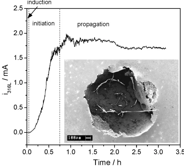
Figure 4 shows a typical curve of the current variations of the SS electrode in a 0.5 M sulfuric solution during the initiation and the propagation of a single pit. At time t = 30 s chloride ions were released at a rate of 10 L/h. The curve can be divided into three distinct parts:
7 (i) the induction phase between the chloride ions release to the onset of the pitting current during which the chloride ions worked their way through the passive layer to reach the metal surface. As noticed in our previous work, the electrode potential during the passive layer formation markedly affects the protectiveness of the passive layer [17]. The lower the potential; the easier the breakdown of the passive film and the shorter the induction period. As noted above, the passive film was formed in-situ by holding a potential of 0 V/MSE during 30 min, leading to an induction period of 15 seconds. According to Haupt and Strehblow [22], the passive layer thickness in this case should be comprised between 1.0 and 1.5 nm. Higher potential values, giving rise to thicker hardly penetrable layers, were intentionally avoided in order to obtain a single pit at the center of the electrode, but also to shorten the induction phase and consequently make easier the correlation between the amounts of injected of chloride ions and dissolved SS. However,
(ii) the pit initiation phase in which the bare metal zone started to dissolve at a high rate. The dissolution current increased progressively during 45 min to reach a threshold marking the beginning of the last phase.
(iii) the pit propagation phase. The latter phase may last for long duration time (some experiments were performed for more than 5 hours) as long as chloride ions are being brought into the capillary-substrate thin layer. Of importance in the propagation phase is the steadiness of the corrosion current, offering the prospect of studying this phase by means of electrochemical impedance spectroscopy (EIS).
The as-obtained single pit shown in the inset of Fig. 4 was located expectedly beneath the capillary. It grew under the surface layer of the SS below a cover. Removing the cover revealed a nearly hemispherical pit. Over a period of 3 hours, the pit grew to 1.4 mm in diameter and 450 m in depth. Numerous researchers have already observed such perforated layer covering pits on SS [9, 10, 23-28]. Among them, Mankowski and
Szklarska-8 Smialowska [23] noticed colored streams of the solution escaping from time to time the pits initiated on 316 Ti. A similar stream was observed in this study as the solution turned green in the vicinity of the pit because of the salt film output. When in-situ probed using microprobe X-ray fluorescence [5] and most recently by synchrotron X-ray diffraction [29], FeCl2 was
found to be the main constituent of the salt film formed over dissolving 316L SS in acidic media, beside little nickel and chromium. In our experiment, a syringe was introduced inside the pit in order to collect the green salt solution. Subsequently, the withdrawn solution was dried and the as-obtained powder was analyzed by EDAX spectroscopy. The EDAX spectrum shows a composition of about 70 at.% of iron, 19 at.% of chromium, and 11 at.% of nickel, indicating that there was no selective dissolution of the 316L SS, in good agreement with a previous quantification of the elements involved in the dissolved corrosion products using inductively coupled plasma mass spectrometry [17].
4. Conclusion
A novel set-up suited to uniformly initiate a single pit with chloride ions was designed. All the as-obtained pits were observed to grow hemispherically under a metallic cover. The single pit dissolution current increased progressively to reach a threshold marking the beginning of a steady current phase that might be further studied by means of EIS. To date, the role of the Cl- ions in the solution remains not yet fully understood. Hence, monitoring the Cl- ions supply to a single active pit would contribute to shed some light on their role in the metal dissolution process. The results of our on-going work on this topic will be the topic of a detailed article.
Acknowledgements
10 REFERENCES
[1] G.T. Burstein, P.C. Pistorius, S.P. Mattin, The nucleation and growth of corrosion pits on stainless steel, Corros.Sci., 35 (1993) 57-62.
[2] G.T. Burstein, S.P. Mattin, The nucleation and early stages of growth of corrosion pits, Proc.- Electrochem.Soc., 95-15 (1996) 1-14.
[3] G.S. Frankel, L. Stockert, F. Hunkeler, H. Boehni, Metastable pitting of stainless steel, Corrosion (Houston), 43 (1987) 429-436.
[4] P.C. Pistorius, G.T. Burstein, Growth of corrosion pits on stainless steel in chloride solution containing dilute sulfate, Corros.Sci., 33 (1992) 1885-1897.
[5] H.S. Isaacs, J.H. Cho, M.L. Rivers, S.R. Sutton, In situ x-ray microprobe study of salt layers during anodic dissolution of stainless steel in chloride solution, J.Electrochem.Soc., 142 (1995) 1111-1118.
[6] T.R. Beck, R.C. Alkire, Occurrence of salt films during initiation and growth of corrosion pits, J.Electrochem.Soc., 126 (1979) 1662-1666.
[7] J.W. Tester, H.S. Isaacs, Diffusional effects in simulated localized corrosion, J.Electrochem.Soc., 122 (1975) 1438-1445.
[8] H.S. Isaacs, Behavior of resistive layers in the localized corrosion of stainless steel, J.Electrochem.Soc., 120 (1973) 1456-1462.
[9] P. Ernst, R.C. Newman, Pit growth studies in stainless steel foils. I. Introduction and pit growth kinetics, Corros.Sci., 44 (2002) 927-941.
[10] H.S. Isaacs, G. Kissel, Surface preparation and pit propagation in stainless steels, J. Electrochem. Soc., 119 (1972) 1628-1632.
[11] P.C. Pistorius, G.T. Burstein, Metastable pitting corrosion of stainless steel and the transition to stability, Philos.Trans.R.Soc.London, Ser.A, 341 (1992) 531-559.
[12] P.C. Pistorius, G.T. Burstein, Detailed investigation of current transients from metastable pitting events on stainless steel - the transition to stability, Mater.Sci.Forum, 111-112 (1992) 429-452.
[13] B. Vuillemin, X. Philippe, R. Oltra, V. Vignal, L. Coudreuse, L.C. Dufour, E. Finot, SVET, AFM and AES study of pitting corrosion initiated on MnS inclusions by
microinjection, Corros.Sci., 45 (2003) 1143-1159.
[14] K. Fushimi, M. Seo, Initiation of a local breakdown of passive film on iron due to chloride ions generated by a liquid-phase ion gun, J. Electrochem. Soc., 148 (2001) B450-B456.
[15] C. Gabrielli, S. Joiret, M. Keddam, N. Portail, P. Rousseau, V. Vivier, Single pit on iron generated by SECM, Electrochim. Acta, 53 (2008) 7539-7548.
[16] J.W. Still, D.O. Wipf, Breakdown of the iron passive layer by use of the scanning electrochemical microscope, J. Electrochem. Soc., 144 (1997) 2657-2665.
[17] N. Aouina, F. Balbaud-Celerier, F. Huet, S. Joiret, H. Perrot, F. Rouillard, V. Vivier, Single pit initiation on 316L austenitic stainless steel using scanning electrochemical microscopy, Electrochim. Acta, 56 (2011) 8589-8596.
[18] C. Gabrielli, S. Joiret, M. Keddam, H. Perrot, N. Portail, P. Rousseau, V. Vivier, Development of a Coupled SECM-EQCM Technique for the Study of Pitting Corrosion on Iron, J. Electrochem. Soc., 153 (2006) B68-B74.
[19] M.A. Alpuche-Aviles, D.O. Wipf, Impedance feedback control for scanning electrochemical microscopy, Anal. Chem., 73 (2001) 4873-4881.
[20] C. Gabrielli, F. Huet, M. Keddam, P. Rousseau, V. Vivier, Scanning Electrochemical Microscopy Imaging by Means of High-Frequency Impedance Measurements in Feedback Mode, J. Phys. Chem. B, 108 (2004) 11620-11626.
11 [21] H. Bouazaze, J. Fransaer, F. Huet, P. Rousseau, V. Vivier, Electrolyte-resistance change due to an insulating sphere in contact with a disk electrode, Electrochim. Acta, 55 (2010) 1645-1655.
[22] S. Haupt, H.H. Strehblow, A combined surface analytical and electrochemical study of the formation of passive layers on Fe/Cr alloys in 0.5 M H2SO4, Corros.Sci., 37 (1995) 43-54.
[23] J. Mankowski, Z. Szklarska-Smialowska, Accumulation of chloride ions in pits growing during anodic polarization, Corros.Sci., 15 (1975) 493-501.
[24] I.L. Rosenfeld, I.S. Danilov, Electrochemical aspects of pitting corrosion, Corros.Sci., 7 (1967) 129-142.
[25] R. Ke, R. Alkire, Surface analysis of corrosion pits initiated at manganese sulfide inclusions in 304 stainless steel, J.Electrochem.Soc., 139 (1992) 1573-1580.
[26] N.J. Laycock, S.P. White, J.S. Noh, P.T. Wilson, R.C. Newman, Perforated covers for propagating pits, J.Electrochem.Soc., 145 (1998) 1101-1108.
[27] P. Ernst, N.J. Laycock, M.H. Moayed, R.C. Newman, The mechanism of lacy cover formation in pitting, Corros.Sci., 39 (1997) 1133-1136.
[28] S.M. Ghahari, A.J. Davenport, T. Rayment, T. Suter, J.P. Tinnes, C. Padovani, J.A. Hammons, M. Stampanoni, F. Marone, R. Mokso, In situ synchrotron X-ray
micro-tomography study of pitting corrosion in stainless steel, Corros.Sci., 53 (2011) 2684-2687. [29] T. Rayment, A.J. Davenport, A.J. Dent, J.P. Tinnes, R.J.K. Wiltshire, C. Martin, G. Clark, P. Quinn, J.F. Mosselmans, Characterisation of salt films on dissolving metal surfaces in artificial corrosion pits via in situ synchrotron x-ray diffraction, Electrochem.Commun., 10 (2008) 855-858.
Figure 1. Experimental setup used to generate and sustain the growth of a single pit on a 316 L SS substrate. Inset: 100 m inner diameter and 900 m outer diameter glass capillary.
-80
-60
-40
-20
0
-0.425
-0.420
-0.415
-0.410
-0.405
-0.400
V
Re/ V
z / µm
Figure 2. Probe approach curve with the electrolyte resistance technique. The probe was moved at a scan rate v = 10 m s-1
Figure 3. Electrolyte resistance scans over the 316 L stainless steel electrode. The tip was moved at a scan rate v = 10 m s-1
, E316L = 0 V/MSE. Black line: along the x-axis (left and
Figure 4. Evolution of the current generated by a single pit on a 316L substrate in 0.5 M H2SO4. Tip-to-substrate distance z = 10 m, E316L = 0 V/MSE. Inset: SEM observation of the
pit generated and sustained during 3 hours. The pit was uncovered prior to SEM observation.