Cycle-by-Cycle Analysis of Cold Crank-Start in a GDI Engine
The MIT Faculty has made this article openly available. Please share
how this access benefits you. Your story matters.
Citation
Rodriguez, J. Felipe, and Wai K. Cheng. “Cycle-by-Cycle Analysis of
Cold Crank-Start in a GDI Engine.” SAE Int. J. Engines 9, no. 2 (April
5, 2016).
As Published
http://dx.doi.org/10.4271/2016-01-0824
Publisher
SAE International
Version
Author's final manuscript
Citable link
http://hdl.handle.net/1721.1/102389
Terms of Use
Creative Commons Attribution-Noncommercial-Share Alike
Page 1 of 11
2016-01-0824
Cycle-by-cycle analysis of cold crank-start in a GDI engine
Author, co-author (
Do NOT enter this information. It will be pulled from participant tab in
MyTechZone
)
Affiliation (Do NOT enter this information. It will be pulled from participant tab in MyTechZone)
Abstract
The first 3 cycles in the cold crank-start process at 20°C are studied in a GDI engine. The focus is on the dependence of the HC and PM/PN emissions of each cycle on the injection strategy and combustion phasing of the current and previous cycles. The PM/PN emissions per cycle decrease by more than an order of magnitude as the crank-start progresses from the 1st to the 3rd cycle, while the HC emissions stay
relatively constant. The wall heat transfer, as controlled by the combustion phasing, during the previous cycles has a more significant influence on the mixture formation process for the current cycle than the amount of residual fuel. The results show that the rise in HC emissions caused by the injection spray interacting with the intake valves and piston crown is reduced as the cranking process progresses. Combustion phasing retard significantly reduces the PM emission. The HC emissions, however, are relatively not sensitive to combustion phasing in the range of interest.
Introduction
In response to growing concerns over global warming and climate change, the CO2 emissions legislations around the world have become
increasingly stringent. Figure 1 shows the evolution of the CO2
legislation for light duty vehicles (LDV) in different parts of the world as they strive towards a goal of approximately 100 grams of CO2 per
kilometer during the next decade.
Figure 1. Light duty vehicles CO2 emissions regulations around the world.
Data normalized to NEDC. Adapted from [1]
The tightening of the fuel consumption standards has been a driver for the adoption of new technologies during the past decade; among them gasoline direct injection (GDI) engines. According to EPA and NHTSA estimates [2], downsized turbocharged GDI engines with cooled EGR have a potential for CO2 emissions reduction between
16% and 25% compared to the 2008 gasoline engine (PFI, NA) used as a baseline. As this potential has been tapped during the past decade the market penetration of GDI engines has grown at an accelerated pace (see Fig. 2). Despite the advantages in fuel consumption of GDI engines, the liquid fuel injection into the combustion chamber poses emissions challenges, particularly during the cold-start phase where over 95% of the HC [5] and over 75% of the PM/PN [6] tailpipe emissions take place.
Figure 2. Market penetration of GDI engines in the US and the EU for the past decade. Data source: US [3]; EU [4]
Figure 3 shows the engine behavior during a typical cold crank-start of a GDI engine. Prior to the first combustion cycle the engine is driven by the starter motor at approximately 280 rpm. After the 1st combustion
event the engine speed increases rapidly and reaches its maximum speed (a.k.a. speed flare) within 1 second. After the speed flare, the engine speed decreases to the targeted cold fast-idle speed. As can be seen from the cumulative engine out emissions in Fig. 4, the engine cold crank-start is responsible for a disproportionate amount of the cold-start phase emissions. During the initial 4 seconds (0.2% of the total FTP-75 duration) 110 mg of HC and 5 mg of PM were emitted, corresponding to 32% and 15% of the T3B50 limit respectively. In comparison to all the other operation points during the certification driving cycle, the cold crank-start is subject to the lowest temperature and lowest engine speed. As a result, the fuel evaporation and mixture formation process are compromised and significant over-fueling is necessary to produce an ignitable fuel-air mixture. Because of the large
Canada China India Japan EU g C O2 / k m n o rm al iz ed t o N E D C 100 140 180 220 260 Year 2000 2005 2010 2015 2020 2025 USA G D I m ar k et s h ar e / % 0 10 20 30 40 Year 2002 2004 2006 2008 2010 2012 2014 EU USA
Page 2 of 11
amount of fuel injected, a significant portion of the injected fuel lands on the cold combustion chamber surfaces, resulting in fuel films that fail to evaporate before combustion. Optical investigations conducted by Costanzo et al. [7] provide evidence of the significant role that these fuel films play on HC emissions and PM formation. Additionally, the low temperature impacts negatively the classical HC emissions mechanisms identified by Cheng et al. [8]; low temperature results in larger crevice volumes, increases the solubility of hydrocarbons into the lubricant oil layer, and intensifies the heat transfer rates from the hot gases into the cylinder walls. The latter increases the flame quenching distance and reduces the post-flame oxidation rate of the resulting pollutants after combustion.
Figure 3. Cylinder pressure, engine speed and intake manifold pressure traces during cold crank-start.
Figure 4. Cold crank-start cumulative emissions as percentage of the T3B50/ULEV50 limit [9]. The HC limit of T3B50 assumes the same HC/NOx
ratio as the T2B5 standard
This study seeks to expand the understanding of the HC and PM/PN emissions behavior during the cold crank-start process of a GDI engine. For that purpose the initial 3 engine cycles are analyzed individually under a set of parameters that include the mass of injected fuel, the start of injection (SOI), and the ignition timing. Additionally, the interactions between cycles are also considered by studying the impact that the heat transfer history and the residual fuel from previous injection events have on the mixture formation and fuel enrichment requirement of the current cycle.
The research presented on this paper is a natural extension of previous studies by the authors focusing on 1st cycle emissions and fuel pathway
during cold crank-start [9, 10]. This study also builds upon the methodology developed at the Sloan Automotive Laboratory at MIT for experimentally studying the first combustion cycle and the cranking process in PFI engines [11, 12, 13, 14, 15, 16, 17].
Experimental Methodology
Engine set up
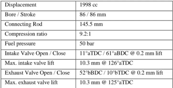
The experiments were carried out using a commercial 4-cylinder, 2 liter GDI engine featuring side-mounted electromagnetic injectors, with a 52° cone angle, a 25° inclination from the horizontal and 6 holes. The variable valve timing (VVT) system was deactivated and a fixed valve timing was used for all of the experiments (see Table 1).
Table 1. Specifications of the GM – LNF engine Displacement 1998 cc Bore / Stroke 86 / 86 mm Connecting Rod 145.5 mm Compression ratio 9.2:1 Fuel pressure 50 bar
Intake Valve Open / Close 11°aTDC / 61°aBDC @ 0.2 mm lift Max. intake valve lift 10.3 mm @ 126°aTDC
Exhaust Valve Open / Close 52°bBDC / 10°bTDC @ 0.2 mm lift Max. exhaust valve lift 10.3 mm @ 125°aTDC
In real GDI applications the typical fuel pressure for the initial injection events during cranking ranges between 30 and 70 bar [18, 19] and is heavily dependent on engine speed. In the experimental setup used in this study, the fuel pressure was kept independent from engine operation and was maintained at a constant value of 50 bar by a hydro-pneumatic accumulator (see Fig. 6). A Tier II EEE certification gasoline was used with a carbon mass fraction of 86.5%, 29% aromatics content and a Reid vapor pressure of 62.7 kPa. The distillation curve can be found in Fig. 5. Three independent chillers for the fuel, intake air, engine oil and coolant were used to keep the cold crank-start conditions, with all temperatures at 20°C.
Figure 5. Distillation curve of the used Tier II EEE certification gasoline
The pollutant emissions were monitored at the exhaust runner of cylinder 4 using fast response analyzers. The wet HC mole fraction was measured by a fast FID (Cambustion HFR400) with a 10 to 90% time response of 1 ms. The CO and CO2 wet mole fractions were
measured by a fast NDIR (Cambustion NDIR500) with a 10 to 90% time response of 8 ms. Lastly, the particulate spectrum was measured using a differential mobility spectrometer (Cambustion DMS500) with a size range of 5-1000 nm and a 10 to 90% response of 300 ms.
C y li n d e r P re ss u re / b a r 0 5 10 15 20 25 30 35 M A P / b a r 0.0 0.5 1.0 E n g in e S p ee d / r p m 300 600 900 1200 Time / s 0 1 2 3 4 Neng MAP Pcyl P e rc e n ta g e o f T 3 B 5 0 l im it / % 15 32 PM emissions C u m u la ti v e E m is si o n s HC emissions Cummulative values: HC = 110 mg PM = 5 mg Time / s 0 1 2 3 4 T em p er at u re / ° C 30 60 90 120 150 180 210 Evaporated fraction / % 0 20 40 60 80 100
Page 3 of 11
Figure 6. Diagram of the experimental setup and the sensor locations
In comparison to the fast FID and fast NDIR analyzers, the time response of the DMS is two orders of magnitude slower, precluding crank-angle resolved measurements of the particle spectrum. Still, at t10-90% = 300 ms, the instrument’s response time is sufficient to allow
cycle-resolved measurement. However, as the engine speed increases during crank-start, the time interval between two consecutive exhaust events might not be long enough to allow the DMS to completely differentiate between the emissions of two adjacent engine cycles. To overcome this obstacle for performing a cycle-resolved analysis of the initial 3 cycles, an exhaust gas sampling system (EGSS) is used.
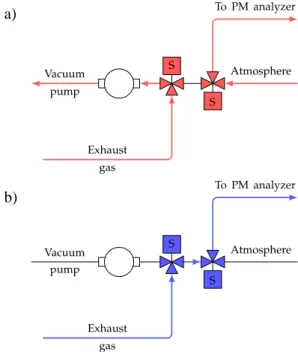
Figure 7. Exhaust gas sampling system (EGSS) for cycle-resolved particle spectrum measurement. a) Closed position feeds ambient air to the analyzer and circulates the exhaust gases to minimize the dead volume. b) Open
position feeds exhaust sample to the analyzer
The objective of the EGSS is to supply to the analyzer only the exhaust gases from the desired cycle, while blocking the exhaust gases from previous and following cycles. The EGSS is located upstream of the DMS (Fig. 6) and consists of two three-way solenoid valves connected in series. In the “closed” position (Fig. 7-a), the exhaust gas is
circulated around the system by a rotary vane vacuum pump to in order to minimize dead volumes, while the DMS is allowed to sample ambient air in order to maintain its internal pressure within range. In the “open” position (Fig. 7-b) the exhaust and sample flows are connected, and the DMS is able to perform the particle spectrum measurement for the desired engine cycle. The solenoid valves have a 3/32’’ orifice and an opening time of 10 ms, which is fast enough to capture the exhaust flow period of 30 – 100 ms. The EGSS is controlled by a programmable microcontroller that uses the crankshaft encoder signal as an input for the timely triggering of the solenoid valves.
The emission values reported in this paper are presented in terms of mass per cylinder per cycle. Due to the transient nature of the experiments, it is difficult to measure the time-resolved exhaust flow rate using an air-flow meter. Instead, the in-cylinder pressure during the exhaust stroke was used to calculate the exhaust mass flow rate. The latter was then integrated with the concentration measurements over the exhaust stroke. Further details on the methodology used to convert the mole fraction and concentration values to mass emissions per cycle can be found in Ref. [9].
Experiment description
As pointed out in the experimental layout description (see Fig. 6), the study was done via cylinder #4 with the engine operating in single-cylinder mode. A direct consequence of this approach is the inability to achieve a speed transient that is representative of a 4-cylinder engine during crank-start. To circumvent this, the engine was torque-assisted by a 10hp electric motor during the simulated crank-start experiments. The motor control and speed-ramp were adjusted to achieve similar speed traces between multi-cylinder and single-cylinder crank-start (Fig. 8).
In all cases, an experimental run started with the engine motoring at cranking speed while the temperatures and the exhaust HC background concentration were monitored until steady state condition was achieved. After the steady-state motoring, and depending on the engine cycle of interest, one, two or three combustion events took place in cylinder 4 (see Fig. 8 a-c). Thereafter, engine was motored at a fixed speed for 50 additional engine cycles while the exhaust flow composition and temperatures were recorded. The engine was brought again to cranking-speed motoring until the purging of residual HC was completed and the steady-state condition was attained. Five experiments were performed for each experimental condition; the average values are reported.
Table 2. Operation parameters for the 1st, 2nd, and 3rd cycles
Parameter 1st cycle 2nd cycle 3rd cycle
Engine speed / rpm 280 800 1050
MAP (mbar) 900 750 600
Fuel mass (FEF=1) / mg 29.5 26 21 FEF / - 1.7 … 3.3 1.5 … 2.1 1.3 … 1.9 SOI / °CA aTDCintake. 45 … 315 45 … 315 45 … 315
Spark timing / °CA aTDCcomp. -45 … 5 -45 … 5 -45 … -5
Throughout all of the experiments the throttle opening was fixed at the fast-idle position (2 bar NIMEP, 1200 rpm). The engine operated in the open-loop mode with the fuel amount being a function of the
a)
Page 4 of 11
demanded enrichment, the engine speed and the intake manifold pressure (speed-density calibration). Table 2 contains a summary of the typical values of the relevant parameters for the initial 3 engine cycles.
Figure 8. Representative engine speed and pressure traces for the 1st (a), 2nd
(b), and 3rd (c) cycle experiments
Results and discussion
The results contained in this section deal with the effects of different parameters on the HC and PM/PN emissions performance of the initial 3 cycles during cold crank-start. The parameters studied are the spark timing, start of injection (SOI), and the fuel enrichment factor (FEF). The FEF is a dimensionless parameter used to quantify the fuel mass injected compared to the amount of fuel required to form a stoichiometric mixture with the inducted air; it is defined as follows:
𝐹𝐸𝐹 = 𝑚𝑓,𝑐𝑦𝑙
𝑉𝑐𝑦𝑙∙ 𝜂𝑣𝑜𝑙∙ 𝜌𝑖𝑛𝑡∙ (𝐹/𝐴)𝑠𝑡𝑜𝑖𝑐ℎ (1)
The volumetric efficiency ηvol is referenced to the intake manifold
condition; it is calibrated by motoring at steady state with the same engine speed as the instantaneous value during cranking.
Fuel enrichment factor effect
1st cycle of cranking dependence on FEF1st
The impact of the FEF1st on the 1st cycle HC and PM emissions has
been covered in detail in a previous publication by the authors [9]. It is discussed here in connection to the 2nd cycle of cranking. Some of
the most important results and trends are shown in Fig 9.
Figure 9. Calculated λ, CO, HC and PM emissions as a function of FEF1st for
the 1st cycle; λ calculated using the measured CO
2 and CO mole fractions
At FEF1st=1.7 the resulting mixture is too lean and the cycle is a
misfire. From FEF1st =2.1 complete combustion takes place and the
emissions plateau at 1.2 mg HC, 10 µg PM and 0.4 mg CO. For FEF1st
greater than 2.7 all emissions increase rapidly, even though the overall λ of combustion ( based on the exhaust CO and CO2 values) is larger
than 1.2. Based on these results FEF1st=2.5 was selected as nominal 1st
cycle FEF for further testing.
E n g in e S p ee d / r p m 280 1200 Multi-cylinder crank-start Motor-assisted single-cylinder mode P re ss u re ( cy l. 4 ) / b ar 0 20 40 60
Cycle number (cyl. 4) /
-1 2 3 4
Single combustion event
E n g in e S p ee d / r p m 280 830 Multi-cylinder crank-start b) P re ss u re ( cy l. 4 ) / b ar 0 20 40 60
Cycle number (cyl. 4) /
-1 2 3 4
Two combustion events
E n g in e S p ee d / r p m 280 1050 Multi-cylinder crank-start c) Motor-assisted single-cylinder mode P re ss u re ( cy l. 4 ) / b ar 0 20 40 60
Cycle number (cyl. 4) /
-1 2 3 4
Three combustion events
a)
1st cycle. Cyl. 4. SOI = 195°CA aTDC intake
Spark = -10°CA aTDCcomp.
FEF 1st cycle / -1.7 2.1 2.5 2.9 3.3 P M e m is si o n s / µ g 0 50 100 150 200 H C e m is si o n s / m g 0.5 1.0 1.5 2.0 C o m b u st io n / -1.0 1.2 1.4 1.6 1.8 2.0 C O e m is si o n s / m g 0 1 2 3 4 5
Page 5 of 11
2nd and 3rd cycle dependence on FEF2nd and FEF3rd
Figure 10. Values of λ, CO, HC and PM emissions as a function of FEF for the 2nd and 3rd cycle. The green band corresponds to the FEF selected for the
subsequent SOI and spark timing sweep experiments
As it is the case with the 1st cycle, which is already discussed at the
beginning of this section, the 2nd and 3rd cycle pollutant emissions are
also dependent on the current cycle’s FEF. Figure 10 shows combustion λ, CO, HC and PM emissions for the 2nd and 3rd cycles as
a function of FEF. Both 2nd and 3rd cycles exhibit similarities in the
trends. The combustion λ decreases linearly with FEF, and with similar slopes in both cases (increasing FEF by 0.2 would decrease combustion by approximately 0.1). As the combustion λ decreases to below 1.1, the CO emissions show a steep increase (Fig. 10-a and 10-c). The HC emissions show a slight increase with FEF; the 2nd and
3rd cycles HC emissions increase in 0.07 mg for an increase in 0.2 in
FEF. The PM emissions also increase with FEF, although they exhibit different slopes for the 2nd and 3rd cycles. For a 0.2 increase in FEF,
the 2nd cycle PM emissions increase in approximately 2.5 µg, while the
3rd cycle PM emissions do it in 0.7 µg.
The observed trends for the initial 3 cycles can be summarized as follows. For a 0.2 increase in FEF:
1st cycle: HC increase ~ 0.1 mg. PM increase ~ 30 µg
2nd cycle: HC increase ~ 0.07 mg. PM increase ~ 2.5 µg
3rd cycle: HC increase ~ 0.07 mg. PM increase ~ 0.7 µg
2nd cycle dependence on 1st cycle strategy
As can be inferred from the 1st cycle analysis in Fig. 9, more than half
of the fuel injected in the 1st cycle does not participate in combustion.
The remaining fuel is either pushed back into the intake manifold before IVC, absorbed into the lubricant oil, stored in the combustion chamber in the form of fuel films or lost to the crank-case in the form of blow-by gases. Some of this fuel will return to the cylinder, desorb from the oil layer or evaporate from the fuel films before the 2nd
ignition event and participate in combustion. Given the importance of the residual fuel on the mixture formation process, it must be included in the analysis of the 2nd cycle FEF
2nd requirement. In a previous study
by the authors [10] the residual fuel available for combustion was quantified for the 2nd cycle by means of fuel carbon accounting using
the HC exhausted from a non-firing 2nd cycle (see Fig. 11 bottom).
Figure 11. Top: 2nd cycle equivalent fuel mass exhausted as a function of the
residual fuel for several 2nd cycle FEF
2nd. Bottom: Residual fuel from the 1st
cycle as a function of the 1st cycle’s FEF 1st.
The concept of the equivalent fuel mass exhausted (EFME) is introduced to facilitate the study of the impact that the residual fuel from the 1st cycle has on the mixture formation of the 2nd cycle. The
EFME represents the amount of fuel necessary to produce the observed carbon mass exhausted, in the form of CO2, CO and HC, in a given
cycle (see Eq. 2).
𝐸𝐹𝑀𝐸 = 𝑚𝐻𝐶+ 1 𝑥𝐶,𝑓𝑢𝑒𝑙(𝑚𝐶𝑂2 𝑀𝐶 𝑀𝐶𝑂2+ 𝑚𝐶𝑂 𝑀𝐶 𝑀𝐶𝑂) (2)
Thus EFME represents the amount of fuel vapor available for combustion in the cycle.
Figure 11 (top) shows the EFME of the 2nd cycle as a function of the
residual fuel for the case FEF2nd = 1.7. The EFME increases linearly
with the residual fuel. The resulting slope shows that an increase in 1 mg in residual fuel would result in an increase of 2.9 mg in EFME. The experiment was repeated at FEF2nd values of 1.5, 1.9 and 2.1, and a
similar slope was observed.
Figure 12. Wall heat transfer as a function of FEF1st for the 1st cycle SOI = 180°CA aTDCintake
Spark = -10°CA aTDCcomp.
FEF 1st cycle = 2.5 2nd cycle. Cyl. 4. FEF 2nd cycle / -1.3 1.5 1.7 1.9 2.1 FEF 3rd cycle / -1.3 1.5 1.7 1.9 H C e m is si o n s / m g 0.5 1.0 1.5 2.0 C O e m is si o n s / m g 0.3 0.7 1.1 1.5 C o m b u st io n / -1.0 1.1 1.2 1.3 c) H C e m is si o n s / m g 0.5 1.0 1.5 2.0 d) P M e m is si o n s / µ g 1 3 5 7 9 b) C o m b u st io n / -1.0 1.1 1.2 1.3 1.4 1.5 a) C O e m is si o n s / m g 0.5 1.0 1.5 2.0 2.5 SOI = 180°CA aTDCintake
Spark = -10°CA aTDCcomp.
FEF 1st cycle = 2.5 FEF 2nd cycle = 1.7 3rd cycle. Cyl. 4. P M e m is si o n s / µ g 1 3 4 FEF2nd = 1.7 slope: 2.9 mgEFME / mgres. fuel
Residual fuel from 1st cycle available for 2nd cycle combustion / mg 3.5 4.0 4.5 5.0 FEF 1st cycle / -2.1 2.5 2.9 3.3 2 n d c y cl e eq u iv al en t fu el e x h au st ed / m g 20 21 22 23 24 25
Residual fuel from 1st cycle / mg 3.5 4.0 4.5 5.0 W al l h ea t tr an sf er r at e / k W 0 10 20 30 40
Piston position / - EVO Increasing FEF 1st cycle W al l h ea t tr an sf er / J 500 700 900 FEF 1st cycle / -2.1 2.5 2.9 3.3 slope: 385 J /
-Page 6 of 11
That the increase of EFME is faster than the increase in residual fuel is explained as follows. The impact of the 1st cycle FEF
1st on the 2nd
cycle mixture formation goes beyond the contribution of residual fuel from the 1st to the 2nd cycle. The 1st cycle fuel amount has a significant
effect on the NIMEP1st and on the combustion phasing at fixed spark
timing [9]. As the heat release increases and is shifted to earlier points with higher 1st cycle FEF
1st, the wall heat transfer during the 1st cycle
increases as well. Figure 12 shows the total wall heat transfer as a function of FEF1st during the 1st cycle. The heat transfer rate was
calculated using the Woschni [20] correlation corrected for low engine speeds [21].
The corresponding increase in cylinder wall temperature has an influence on the mixture formation process of the 2nd cycle, as it favors
the evaporation of the injected fuel. In order to assess the impact of the wall heating during the 1st cycle on the 2nd cycle mixture formation,
the effect of residual fuel is separated from that of wall heating via two sets of experiments:
1. 1st cycle wall heat transfer sweep, controlled with 1st cycle spark
timing, at constant FEF1st and residual fuel.
2. Residual fuel sweep at constant wall heat transfer in the first cycle. The procedure is achieved by suppressing the spark so that the 1st cycle does not fire; i.e. there is no combustion heat
transfer.
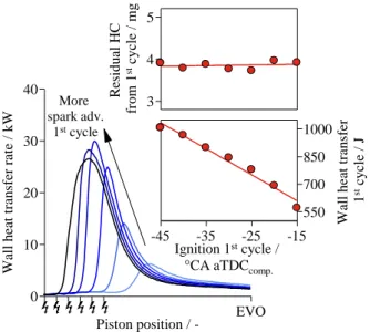
Figure 13. Wall heat transfer and residual fuel as a function of spark timing for the 1st cycle
For the first set of experiments, the wall heat transfer increases with spark advance; at the same time the residual fuel mass remains approximately unchanged; see Fig. 13. The spark timing sweep range was selected to achieve a similar heat transfer range as the one resulting from the 1st cycle FEF
1st sweep (Fig. 12). The dependence of
the 2nd cycle equivalent fuel mass exhausted as a function of the 1st
cycle total wall heat transfer for the case FEF2nd = 1.7 is shown in Fig.
14. As the 1st cycle wall heat transfer is increased (through 1st cycle
spark advance) the 2nd cycle EFME increases. Using a linear fit, the
slope indicates that a 100 J increase in heat transfer would result in a 1mg increase in EFME. To further confirm the validity of these observations, the experiment was repeated at FEF2nd values of 1.5, 1.9
and 2.1; similar dependences of the EFME on the 1st cycle heat transfer
were observed.
Figure 14. 2nd cycle equivalent fuel mass exhausted as a function of the wall
heat transfer during the 1st cycle at constant residual fuel
For the second set of experiments, the 2nd cycle EFME as a function of
the residual fuel, at constant 1st cycle wall heat transfer is shown in Fig.
15. The constant heat transfer condition was obtained by suppressing the ignition during the 1st cycle. In this way, the wall heat transfer is
only a result of the mixture compression. The residual fuel range achieved with this approach is between 3.5 and 6.5 mg (Fig. 15 bottom). As shown in Fig. 15 (top), the increase in 2nd cycle EFME
exhibits a monotonic trend with residual fuel. When the results are fitted linearly, the observed slope shows almost a 1-to-1 correspondence. Thus in the absence of change in wall temperature due to change in heat transfer, the increase in EFME corresponds to the increase in residual fuel from the previous cycle.
For consistency, the experiment was repeated at FEF2nd values of 1.9
and 2.1, and a similar trend of 2nd cycle EFME against the residual fuel
from the 1st cycle (constant 1st cycle heat transfer) was observed.
Figure 15. 2nd cycle equivalent fuel mass exhausted as a function of the
residual fuel from the 1st cycle at constant heat transfer (1st cycle misfire)
The relative importance of the residual fuel and the wall heating effects on EFME of the 2nd cycle may be assessed as follows:
∆𝐸𝐹𝑀𝐸 =𝜕𝐸𝐹𝑀𝐸𝜕𝑚 𝑅 ∆𝑚𝑅+ 𝜕𝐸𝐹𝑀𝐸 𝜕𝑄 𝜕𝑄 𝜕𝐹𝐸𝐹1𝑠𝑡 ∆𝐹𝐸𝐹1𝑠𝑡 (3) W al l h ea t tr an sf er r at e / k W 0 10 20 30 40
Piston position / - EVO
More spark adv. 1st cycle W al l h ea t tr an sf er 1 st c y cl e / J 550 700 850 1000 Ignition 1st cycle /
°CA aTDCcomp.
-45 -35 -25 -15 R es id u al H C fr o m 1 st c y cl e / m g 3 4 5 slope: 1 mgEFME / 100 J 2 n d c y cl e eq u iv al en t fu el e x h au st ed / m g 21 22 23 24 25 26
Wall heat transfer during 1st cycle / J
550 700 850 1000 FEF2nd = 1.7
Residual fuel from 1st cycle misfire
available for 2nd cycle
combustion / mg 3.5 4.5 5.5 6.5 FEF 1st cycle / -(No combustion) 0.9 1.1 1.3 1.5 1.7 2 n d c y c le e q u iv a le n t fu e l e x h a u st e d / m g 17 18 19 20
Residual fuel from 1st cycle / mg
3.5 4.5 5.5 6.5 slope:
0.9 mgEFME / mgres. fuel
Page 7 of 11
Here mR is the residual fuel mass from the 1st cycle and Q is the wall
heat transfer in the 1st cycle. On the right-hand-side of Eq. (3), the first
term represents the change of EFME in the second cycle due to the presence of the residual fuel from the first cycle; the second term represents the change of that due to the change in wall heat transfer in the first cycle.
The partial derivatives may be obtained from the experimental data:
From Fig. 15, 𝜕𝐸𝐹𝑀𝐸 𝜕𝑚 𝑅 ⁄ = 0.9 From Fig. 14, 𝜕𝐸𝐹𝑀𝐸 𝜕𝑄⁄ = 10−2 mg/J From Fig. 12, 𝜕𝐸𝐹𝑀𝐸 𝜕𝐹𝐸𝐹 1𝑠𝑡 ⁄ = 385 J
For the data shown in Fig. 11, for a change of 1st cycle FEF
1st from 2.1
to 3.3 (ΔFEF1st = 1.2), mR increases from 3.6 to 4.95 mg (ΔmR = 1.35
mg). Then numerical values for Eq. (3) become:
∆𝐸𝐹𝑀𝐸 = 1.22 𝑚𝑔 + 4.62 𝑚𝑔 = 5.84 𝑚𝑔 (4)
The above value is in line with the observed value of ΔEFME = 4.1 mg in Fig. 11. More importantly, Eq. (4) shows that the effect of the change of the wall heat transfer in the 1st cycle on the second cycle
EFME is approximately 4 times that of the residual fuel amount.
Start of Injection (SOI) effect
The injection timing is an important parameter for the GDI cold-start calibration. The effect of SOI on the mixture formation process and engine out emission has been studied in the past for the 1st combustion
cycle [9] and for the cold fast-idle period [22, 23]. In this section the analysis is extended to the 2nd and 3rd cycles. The FEF and spark timing
were held constant for each cycle as well as the SOI of the preceding cycles. The relevant experimental parameters used can be found in Table 3. The choice of these values would give good HC and PM emissions for the reference cases; see Fig. 9 and 10.
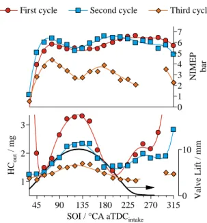
Figure 16. NIMEP and HC emissions as a function of SOI for the 1st, 2nd and
3rd cycles during crank-start
Table 3. Start of injection sweep parameters for the 1st, 2nd, and 3rd cycles
Parameter 1st cycle 2nd cycle 3rd cycle
FEF / - 2.5 1.7 1.5
Fuel mass / mg 74 44 32
Injection duration / °CA 11 15 16 Spark timing / °CA aTDCcomp. -10 -10 -10
SOI (previous cycles) / °CA aTDCintake 180 180 -
The NIMEP and HC emissions as a function of the injection timing are shown in Fig. 16 for the initial 3 cycles. The trends observed in the SOI sweeps are similar in shape for the initial 3 cycles, although the magnitudes differ. The following discussion applies to all 3 cycles studied. Injection timings earlier than SOI = 45°CA aTDCintake cause
significant piston impingement and poor mixture formation. As SOI is retarded the piston impingement is reduced, favoring the mixture preparation and resulting in a sharp increase in NIMEP. At SOI = 75°CA aTDCintake the NIMEP reaches a local maximum and the HC
emissions start to increase rapidly. From SOI = 75 to 180°CA aTDCintake the interaction between the injection spray and the intake
valve has a noticeable effect on the NIMEP and HC emissions. The intake valve lift profile is shown in Fig. 16 (bottom). The maximum intake valve lift corresponds with a local minimum in NIMEP and a local maximum in HC emissions. However, as the crank-start progresses from the 1st to the 3rd cycle, the spray/valve interaction has
a diminishing impact on HC emissions and an increasing effect on NIMEP (see Table 4).
Table 4. Effect of spray/valve interaction on NIMEP and HC emissions for the initial 3 cycles.
Parameter 1st cycle 2nd cycle 3rd cycle
NIMEP @ SOI = 75°CA aTDCintake 5.8 bar 6.4 bar 4.4 bar
NIMEP @ SOI = 120°CA aTDCintake 5.4 bar 5.2 bar 2.7 bar
NIMEP reduction -7 % -19 % -39 % HC @ SOI = 60°CA aTDCintake 1.5 mg 1.3 mg 1.2 mg
HC @ SOI = 120°CA aTDCintake 3.3 mg 2.3 mg 1.6 mg
HC emissions increase +120 % +77 % +33 %
Injection timings in the initial part of the compression stroke, where the intake valve lift is lower than 6 mm, result in a flat region of low HC emissions. As the SOI is further delayed between 240 and 300°CA aTDCintake, the HC emissions increase due to the decay in turbulence
intensity and its negative effect on mixture formation [22]. In the case of the 3rd cycle, the engine misfired and the results are not reported.
After SOI=300°CA aTDCintake, the spray/piston interaction results in
mixture stratification in the vicinity of the spark plug, enabling robust combustion but with an increase in HC emissions.
Figure 17 shows the PM/PN emissions as a function of the SOI for the initial 3 cycles. Common to all 3 cycles, injection timings in the first half of the intake stroke result in higher PM/PN emissions in comparison to SOI in the late intake stroke. In contrast to the HC emissions, the interaction between the injection spray and the intake valve leads to a reduction in PM emissions. In the case of the 1st cycle,
the minimum PM/PN emissions are achieved for SOI during the early compression stroke. After this point the PM emissions increase monotonically with SOI retard, mainly due to interaction with the piston. The 2nd cycle PM/PN dependence on SOI shows a similar
behavior. The SOI for minimum PM/PN is located in the region of
N IM E P b ar 0 1 2 3 4 5 6 7 First cycle Second cycle Third cycle
V al v e L if t / m m 0 10 H Co u t / m g 1 2 3
SOI / °CA aTDCintake
Page 8 of 11
maximum intake valve lift, at approximately SOI=135°CA aTDCintake.
After this point, the decrease in turbulence intensity and the interaction with the piston crown drives the PM/PN emissions up. Lastly, the 3rd
cycle SOI sweep features a region of constant PM emissions for SOI between 120 and 225°CA aTDCintake.
Figure 17. PM emissions and median particle diameter as a function of CA50 for the 1st, 2nd and 3rd cycles during crank-start
The changes observed in PM emissions with SOI and cycle number are significant, covering orders of magnitude. The observed increase in PM with SOI retard is driven by the increase in particle nucleation (PN emissions). The reduction in PM from the 1st to the 3rd cycle is a result
of both lower particle nucleation and reduced agglomeration rate (smaller particle size).
Combustion phasing effect
The use of retarded spark timing during the cold fast-idle period (first 20 sec. of FTP-75) is a common strategy in the cold-start calibration of LDVs [24] for accelerating the catalyst light-off time and reducing the engine-out HC emissions. The reduction in HC emissions with spark retard is mainly associated with the in-cylinder consumption of the fresh mixture stored in the crevice volumes by the flame, with post-flame and exhaust runner oxidation playing less important roles [25]. During the cold crank-start of GDI engines, the significant over-fueling necessary to form a combustible mixture results in the formation of fuel films. The liquid fuel films become a dominant source for HC emissions, comparable to or greater than the crevice storage mechanism [7]. Higher burned gas temperatures in the expansion process with retarded timing promotes both the evaporation and oxidation of the HC contained in the fuel films. Thus, the impact of late combustion phasing on crank-start HC emissions in not straight forward.
Table 5. Spark timing sweep parameters for the 1st, 2nd, and 3rd cycles
Parameter 1st cycle 2nd cycle 3rd cycle
FEF / - 2.5 1.7 1.5
Fuel mass / mg 74 44 32
SOI / °CA aTDCintake. 195 180 180
CA50 (previous cycles) / °CA aTDCcomp. 10 17 -
Figure 18. NIMEP and HC emissions as a function of CA50 for the 1st, 2nd and
3rd cycles during crank-start
Figures 18 and 19 show the dependence of NIMEP, HC and PM emissions on the combustion phasing, quantified by the point for 50% of heat release (CA50). The FEF and SOI were held constant for each cycle; the CA50 of the preceding cycles were also held constant (see Table 5). The selection of the nominal FEF and SOI for each cycle was based on the emissions and NIMEP trends presented on the preceding sections.
Due to the low engine speed and the rapid change in speed during crank-start, especially for the 1st cycle, the usual notion of combustion
phasing for MBT (CA50 ~ 7° aTDCcomp.) does not apply [26]. Figure
18 (top) shows the NIMEP as a function of CA50 for the first 3 cycles. The maximum NIMEP is achieved at CA50 ~10° aTDCcomp. for the 1st
cycle, and at CA50 ~5° aTDCcomp. for the 2nd and 3rd cycles.
The HC emissions of the 1st cycle are insensitive to combustion
phasing, the values remain constant at 1.3 mg/cyl./cycle for the entire sweep. This observation suggests that the 1st cycle HC emissions
predominantly derive from the liquid film. Unlike the crevice stored HC, the fuel vapor from liquid films is not premixed with air, and its oxidation is less sensitive to increased post-flame temperatures associated with the combustion retard. In contrast, the HC emissions for the 2nd and 3rd cycles are reduced with later combustion phasing,
undergoing a 30% reduction for the range of combustion phasing delay in this study. The observation suggests an increasing importance of the crevice mechanism as the liquid film is much reduced in the 2nd and
3rd cycle. P N ( cy l. 4 ) / # /c y cl e 109 1010 1011 M ed ia n p ar ti cl e d ia m et er / n m 50 80 110 140 170
SOI / °CA aTDCintake
45 90 135 180 225 270 315 P M ( cy l. 4 ) / µ g /c y cl e 0.5 5 50 500
First cycle Second cycle Third cycle
H Co u t ( cy l. 4 ) / m g /c y cl e 1 2
CA50 / °CA aTDCcomp.
-25 -5 15 35 55 N IM E P / b ar 1 3 5 7 First cycle Second cycle Third cycle
Page 9 of 11
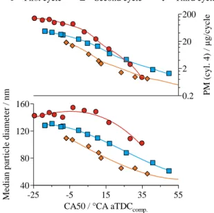
Figure 19. PM emissions and median particle diameter as a function of CA50 for the 1st, 2nd and 3rd cycles during crank-start
The PM/PN emissions as a function of combustion phasing are presented in Fig. 19. The formation of the particulates is driven by the pyrolysis of the fuel rich mixture created by evaporation of the liquid fuel films [22]. As combustion is delayed, the time available for the mixing of the vapor originating from the liquid fuel films increases while the time for particulate nucleation through fuel vapor pyrolysis and accumulation through HC condensation is reduced. As a result, for each of the 3 cycles studied the PM is reduced by more than one order of magnitude with late combustion phasing, due to lower particulate number and smaller median particulate size.
Conclusions
The effects of fuel amount, injection timing and spark timing on the HC and PM emissions of the first 3 cycles during cold crank-start (20°C) were studied in a wall guided gasoline direct injection engine. The main results can be summarized as follows:
1. The adverse conditions of low temperature and limited charge motion (because of the low speed) during cold crank-start result in mixture inhomogeneity. Consequently, aiming for an overall combustion λ of 1 is not a viable strategy as it increases the CO, HC and PM emissions. The amount of fuel injected needs to be large enough to reduce the risk of misfire or partial burn, and sufficiently small to control the engine out emissions. The results show that the optimum fuel enrichment factor (FEF) for the initial 3 cycles are FEF1st =
2.5, FEF2nd = 1.7 and FEF3rd = 1.5.
2. For the range of FEF studied, the HC emissions for the initial 3 cycles are of the same order of magnitude; between 1 and 1.5 mg/cyl./cycle. In contrast, the PM emissions per cycle are reduced by more than an order of magnitude as the crank-start progresses form the 1st to the 3rd cycle.
3. The FEF history has an influence on the mixture formation through two mechanisms. First, as the FEF of previous cycle increases, so does the residual fuel mass. Second, the amount
and point of heat release for the previous cycles is a function of FEF. The heat release increase of the previous cycles translates into wall heating, impacting the fuel evaporation and mixture formation process of the current cycle. The effect of wall heating is estimated to be approximately 4 times that of the residual fuel mass on the amount of combustible fuel vapor prepared in the current cycle. 4. The SOI selection for minimizing the pollutant emissions
presents a tradeoff. The lowest HC emissions are achieved for SOI during the first half of the intake stroke, for intake valve lifts lower than 5 mm. Contrary, the minimum PM emissions are achieved for SOI during the intake stroke with the intake valve lift greater than 5 mm. Injection during the early compression stroke results in a good compromise for both HC and PM emissions.
5. The effect of fuel spray interaction with the intake valve on HC emissions is reduced as the crank-start progresses from the 1st to the 3rd cycle because less fuel is injected in the later
cycles.
6. The HC emissions of the 1st cycle are insensitive to
combustion phasing. For the 2nd and 3rd cycles, spark timing
retard results in approximately a 30% reduction as CA50 goes from -10 to 30° aTDCcomp.. For the 3 cycles studied, the
observed PM reduction with combustion retard is larger than an order of magnitude as CA50 goes from -10 to 30° aTDCcomp..
References
1. Façanha, Cristiano, Kate Blumber, and Josh Miller. “Global Transportation Energy and Climate Roadmap.” International Council on Clean Transportation, 2012.
2. EPA; NHTSA. “Final Rulemaking for 2017-2025 Light-Duty Vehicle Greenhouse Gas Emission Standards and Corporate Average Fuel Economy Standards.” 2012.
3. Davis, Stacy, Susan Diegel, Ridge Boundy, and Sheila Moore. “Vehicle Technologies Market Report 2014.” Oak Ridge National Laboratory, 2015
4. “European Vehicle Market Statistics, 2014.” International Council on Clean Transportation, 2014.
5. Chen, Hai-Ying, and Hsiao-Lan (Russell) Chang. “Development of Low Temperature Three-Way Catalysts for Future Fuel Efficient Vehicles.” Johnson Matthey Technology Review 59, no. 1 (January 1, 2015): 64–67. doi:10.1595/205651315X686011.
6. Myung, Cha-Lee, Juwon Kim, Wonwook Jang, Dongyoung Jin,
Simsoo Park, and Jeongmin Lee. “Nanoparticle Filtration Characteristics of Advanced Metal Foam Media for a Spark Ignition Direct Injection Engine in Steady Engine Operating Conditions and Vehicle Test Modes.” Energies 8, no. 3 (March 9, 2015): 1865–81. doi:10.3390/en8031865.
7. Costanzo, Vincent S., and John B. Heywood. “Effect of In-Cylinder Liquid Fuel Films on Engine-Out Unburned Hydrocarbon Emissions for an SI Engine,” SAE Technical Paper 2012-01-1712, 2012. doi:10.4271/2012-01-1712.
8. Cheng, Wai K., Douglas Hamrin, John B. Heywood, Simone Hochgreb, Kyoungdoug Min, and Michael Norris. “An Overview of Hydrocarbon Emissions Mechanisms in Spark-Ignition
Engines,” SAE Technical Paper 932708, 1993.
doi:10.4271/932708.
9. Rodriguez, J. Felipe, and Wai K. Cheng. “Effect of Operation Strategy on First Cycle CO, HC, and PM/PN Emissions in a GDI
M ed ia n p ar ti cl e d ia m et er / n m 40 80 120 160
CA50 / °CA aTDCcomp.
-25 -5 15 35 55 P M ( cy l. 4 ) / µ g /c y cl e 0.2 2 20 200 First cycle Second cycle Third cycle
Page 10 of 11
Engine.” SAE International Journal of Engines 8, no. 3 (April 14, 2015). doi:10.4271/2015-01-0887.
10. Rodriguez, J. Felipe, and Wai K. Cheng. “Fuel Carbon Pathway in the First Cranking Cycle of a Gasoline Direct Injection Engine.” International Journal of Engine Research, October 5, 2015. doi:10.1177/1468087415609852.
11. Cheng, Wai K., and Fuquan Zhao. “Transient Engine Startup and Shutdown Processes.” In Technologies for Near-Zero-Emission Gasoline-Powered Vehicles, 1–29. SAE International, 2006. 12. Lang, Kevin R., Wai K. Cheng, Mark Borland, Chris Thomas,
and Fuquan Zhao. “Effect of Intake Cam Phasing on First Cycle Fuel Delivery and HC Emissions in an SI Engine.” SAE Technical Paper 2004-01-1852, 2004. doi:10.4271/2004-01-1852.
13. Lang, K. and Wai K. Cheng, "Effect of Fuel Properties on First Cycle Fuel Delivery in a SI Engine," SAE Technical Paper 2004-01-3057, 2004. doi:10.4271/2004-01-3057.
14. Cowart, J., "Air-Fuel Ratio Measurement Diagnostics During Cranking and Startup in a Port-Fuel-Injected Spark-Ignition Engine," SAE Technical Paper 2004-01-1915, 2004. doi:10.4271/2004-01-1915.
15. Santoso, H. and Wai K. Cheng, "Mixture Preparation and Hydrocarbon Emissions Behaviors in the First Cycle of SI Engine Cranking," SAE Technical Paper 2002-01-2805, 2002. doi:10.4271/2002-01-2805.
16. Klein, D. and Wai K. Cheng, "Spark Ignition Engine Hydrocarbon Emissions Behaviors in Stopping and Restarting," SAE Technical Paper 2002-01-2804, 2002. doi:10.4271/2002-01-2804.
17. Chen, Kuo Chiang, Wai K. Cheng, Jane M. Van Doren, James P. Murphy, Matthew D. Hargus, and Sarah A. McSweeney. “Time-Resolved, Speciated Emissions from an SI Engine During Starting and Warm-Up,” SAE Technical Paper 961955, 1996. doi:10.4271/961955.
18. Burke, David, David Foti, James Haller, and William J. Fedor. “Fuel Rail Pressure Rise during Cold Start of a Gasoline Direct Injection Engine,” SAE Technical Paper 2012-01-0393, 2012, doi:10.4271/2012-01-0393.
19. Tang, Huayin, Richard Burke, Sam Akehurst, Chris Brace, et al. “Behaviours of a GDI Gasoline Engine during Start,” SAE Technical Paper 2014-01-1374, 2014. doi:10.4271/2014-01-1374.
20. Woschni, G. “A Universally Applicable Equation for the Instantaneous Heat Transfer Coefficient in the Internal Combustion Engine,” SAE Technical Paper 670931, 1967. doi:10.4271/670931.
21. Lejsek, David, Andre Kulzer, Günter Hohenberg, and Michael Bargende. “Novel Transient Wall Heat Transfer Approach for the Start-up of SI Engines with Gasoline Direct Injection.” SAE
International Journal of Engines 3, no. 1 (April 12, 2010): 1053–
70. doi:10.4271/2010-01-1270.
22. Ketterer, Justin E., and Wai K. Cheng. “On the Nature of Particulate Emissions from DISI Engines at Cold-Fast-Idle.” SAE
International Journal of Engines 7, no. 2 (April 1, 2014): 986–
94. doi:10.4271/2014-01-1368.
23. Cedrone, Kevin, and Wai K. Cheng. “SI Engine Control in the Cold-Fast-Idle Period for Low HC Emissions and Fast Catalyst Light Off.” SAE International Journal of Engines 7, no. 2 (April 1, 2014): 968–76. doi:10.4271/2014-01-1366.
24. Ball, Douglas, Corey Negohosian, Deven Ross, David Moser, and Richard McClaughry. “Comparison of Cold Start Calibrations, Vehicle Hardware and Catalyst Architecture of 4-Cylinder Turbocharged Vehicles.” SAE International Journal of Engines 6, no. 4 (October 14, 2013): 1922–33. doi:10.4271/2013-01-2593.
25. Eng, James A. “The Effect of Spark Retard on Engine-out Hydrocarbon Emissions,” SAE Technical Paper 2005-01-3867, 2005. doi:10.4271/2005-01-3867.
26. Cheng, Wai K., and Fuquan Zhao. “Transient Engine Startup and Shutdown Processes.” In Technologies for Near-Zero-Emission
Gasoline-Powered Vehicles, 1–29. SAE International, 2006.
Contact Information
Felipe Rodríguez, [email protected] Wai Cheng, [email protected]
Acknowledgments
The authors would like to acknowledge the support for this research by Borg-Warner, Fiat Chrysler Automobiles, Ford Motor Company, and General Motors Company through a Consortium on Engine and Fuels Research.
Abbreviations
AFR Air Fuel Ratio
aTDCcomp. After Top Dead Center Compression aTDCintake After Top Dead Center Intake
BDC Bottom Dead Center
CA50 Point for 50% of heat release
CMD Count Median Diameter
DMS Differential Mobility Spectrometer
EFME Equivalent Fuel Mass Exhausted;
see Eq. (2)
EGSS Exhaust Gas Sampling System
FEF Fuel Enrichment Factor; see Eq.
(1)
FFID Fast Flame Ionization Detector
FTP Federal Test Procedure
(𝑭/𝑨)𝒔𝒕𝒐𝒊𝒄𝒉 Stoichiometric fuel air ratio
GDI Gasoline Direct Injection
GPF Gasoline Particle Filter
IVC Intake Valve Closing
IVO Intake Valve Opening
LDV Light Duty Vehicle
MAP Manifold Absolute Pressure
MBT Maximum Brake Torque
𝒎𝒇,𝒄𝒚𝒍 Injected fuel mass per cylinder
𝒎𝒚 Mass exhausted of species y
𝑴𝒚 Molecular weight of species y
Page 11 of 11
NEDC New European Driving Cycle
NIMEP Net Indicated Mean Effective Pressure
PM Particulate Mass
PN Particulate Number
SOI Start of Injection
𝑽𝒄𝒚𝒍 Cylinder volume
TWC Three Way Catalyst
TDC Top Dead Center
𝒙𝑪,𝒇𝒖𝒆𝒍 Carbon mass fraction of fuel
𝜼𝒗𝒐𝒍 Volumetric efficiency