HAL Id: hal-01432057
https://hal.archives-ouvertes.fr/hal-01432057
Submitted on 11 Jan 2017HAL is a multi-disciplinary open access archive for the deposit and dissemination of sci-entific research documents, whether they are pub-lished or not. The documents may come from teaching and research institutions in France or abroad, or from public or private research centers.
L’archive ouverte pluridisciplinaire HAL, est destinée au dépôt et à la diffusion de documents scientifiques de niveau recherche, publiés ou non, émanant des établissements d’enseignement et de recherche français ou étrangers, des laboratoires publics ou privés.
Rough Hydrophobic Surfaces
Li-Hua Luu, Yoël Forterre
To cite this version:
Li-Hua Luu, Yoël Forterre. Giant Drag Reduction in Complex Fluid Drops on Rough Hydropho-bic Surfaces. Physical Review Letters, American Physical Society, 2013, 110, pp.184501 - 184502. �10.1103/PhysRevLett.110.184501�. �hal-01432057�
Giant Drag Reduction in Complex Fluid Drops on Rough Hydrophobic Surfaces
Li-Hua Luu and Yoe¨l ForterreIUSTI, CNRS UMR 7343, Aix-Marseille Universite´, 5 rue Enrico Fermi, 13453 Marseille Cedex 13, France (Received 22 May 2012; revised manuscript received 17 October 2012; published 30 April 2013) We describe a new spreading regime during the drop impact of model yield-stress fluids (Carbopol microgel solutions) on rough hydrophobic surfaces, in a range of parameters where classical Newtonian drops usually splash. For large surface roughness and high impact velocity, we observe that the maximal inertial spreading diameter of the drops can be as much as twice larger than on smooth surfaces in the same conditions, corresponding to apparent basal friction reductions of more than 80%. We interpret this large drag reduction using a simple energy balance model and a dynamic slip length that depends on both the surface roughness and the drop’s dynamics.
DOI:10.1103/PhysRevLett.110.184501 PACS numbers: 47.57.!s, 47.55.D!, 47.85.lb
In fluid dynamics, microscopic details at the solid-liquid interface can have a dramatic influence on the macroscopic flow behavior. Wetting and roughness properties of solid surfaces play a key role in many phenomena involving the static and dynamics of the contact line [1,2], from coating flows to fast inertial flows like drop impact [3,4], penetra-tion of solid bodies into liquids [5], or flow separation from solid surfaces [6]. Surface properties can also affect the classical no-slip hydrodynamic boundary condition at a solid surface [7]. Of particular interest is the possibility to achieve a large effective slip length using textured superhydrophobic surfaces, owing to the strong reduction of the solid-liquid contact area when the liquid is in a ‘fakir’ or Cassie state [8]. This strategy has proven suc-cessful to produce significant skin-friction drag reduction in microfluidic flows or in macroscale turbulent channel flows [9], when the size of the flow gradients becomes comparable to the slip length. However, the extension of this drag-reduction mechanism to other macroscale hydrodynamic configurations—a central issue in many applications—remains largely unexplored.
In this Letter, we address this question in the context of drop impact. When a drop hits a solid surface, a very thin lamella is generated that rapidly spreads radially, providing a unique means to probe the friction drag between a free-surface boundary layer and a solid free-surface. With Newtonian drops, this goal is however hampered by the instability and splashing of the lamella as the velocity increases, especially on textured nonwetting surfaces [3]. Here we show that the use of highly elastic complex fluids (Carbopol microgel solutions) enable us to overcome this splashing limit, giving rise to a new spreading regime. At high impact velocities, Carbopol drops impacting a rough hydrophobic surface (RH) can spread twice farther than when they hit a smooth surface in the same conditions (see Fig. 1 and the movie in the Supplemental Material [10]). This observation strongly contrasts with the case of impacting drops of Newtonian fluids or dilute polymer solutions, for which the maximal (inertial) spreading
diameter Lm is found to be almost independent of the
surface wetting properties [3,11,12] or surface microstruc-ture [13]. Such an increase of spreading, called ‘super-spreading’ in the following, can be interpreted as an apparent reduction of the basal friction between the spread-ing lamella and the rough hydrophobic surface. Assumspread-ing that the initial kinetic energy of the drop"!L3
0V02(! is the
mass density of the drop, L0the drop diameter, and V0the
impact velocity) is balanced by the work of the basal shear stress""bL2mLm(Lm# L0) gives "b/ L!3m , where "bis
the typical magnitude of the basal shear stress. In our case, a twofold increase of the maximal spreading diameter thus corresponds to an apparent drag reduction ð"smooth
b !
"RH
b Þ="smoothb " 85%, a value that greatly exceeds drag
reductions reported previously in steady flow configura-tions using microfabricated superhydrophobic surfaces [9,14].
To study this phenomenon in detail, we measure the maximal spreading diameter as a function of the impact velocity for a wide range of Carbopol concentrations and drop sizes [15], both on a smooth surface (glass) and on a
FIG. 1 (color online). Spreading of a microgel drop (Carbopol ETD 2050 1 wt%, drop size L0¼ 22 mm) impacting at high
velocity (V0¼ 6:15 m=s) a glass surface (left) or a rough hydro-phobic surface (Teflon-coated sandpaper surface P120 grit size) (right). On the coated sandpaper, the maximal spreading diame-ter Lm is about twice that on glass (see also the movie in the
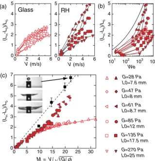
rough hydrophobic surface made with hydrophobic sand particles [see Fig. 2(a)]. At low velocities and/or high concentrations, the normalized maximal drop deformation ðLm! L0Þ=L0 is the same on both kinds of surfaces, as
observed with Newtonian fluids [11]. However, at large velocities and/or low concentrations, the drop deformation is systematically larger on the rough hydrophobic surface. Note that in most experiments, the maximal drop extension is well below the capillary limit controlled by the Weber number We¼ !L0V02=#, where # is the surface tension of
the drop [11]. This means that bulk rheological properties and not surface tension are responsible for the arrest of the spreading in our study. In a previous work [16], we have shown that for a soft yield-stress fluid like Carbopol, elasticity controls the impact dynamics even above the yield stress, because the impact time is much shorter than the fluid relaxation time (large Deborah numbers). In Fig. 2(c), we plot the maximal drop deformation for all data as a function of the elastic Mach number M¼ V0=pffiffiffiffiffiffiffiffiffiffiG=!, where G is the typical elastic shear modulus
of the material (see Fig. 1 in the Supplemental Material [17] for typical rheological curves and a definition of G). A collapse of the data for each impacted surface is observed, confirming the dominant role of elasticity in our study. At low Mach numbers, both master curves coincide. However, above M" 10 a transition is observed and the maximal diameter increases much more rapidly on the rough hydro-phobic surface than on the glass surface.
When seeing pictures of the drop’s dynamics in the superspreading regime [see Fig. 1], one may wonder to what extent the fluid lamella actually touches the solid surface or simply floats over an air layer. Such a thin air cushion is present during the early time dynamics of low viscous drops hitting smooth [18] or micrometer textured surfaces [13], and is believed to play an important role in the splashing transition [19]. Although our very rough surfaces prevent a precise visualization of the contact area, it is possible to test the role of the surface on the spreading by performing impact experiments on small targets [see the inset of Fig. 2(c)]. In this case, the basal friction is negligible during most of the spreading dynamics and the drop’s extension is solely controlled by extensional elasticity and/or capillary effects [20,21]. Figure 2(c) shows that the maximal drop extension on the solid surfaces is always smaller than on the small targets, even in the superspreading cases. Air friction alone cannot explain this difference, as shown by estimation of the bottom viscous drag created by an air layer of thickness "Rq [rms surface roughness] trapped between surface
asperities [22]. It is also unlikely that the superspreading comes from a squeezed air effect between the drop and the solid surface that would push the lamella outward, since the spreading is maximal on the small targets for which squeezed air effects are minimized.
Systematic experiments using coated sandpaper surfaces over a wide range of grit sizes [23] reveal that surface roughness is actually the key parameter in our study. By increasing the surface roughness $ [defined as the mean peak spacing] while keeping all other parameters fixed, it is possible to continuously tune the maximal drop extension between the low value obtained on the glass surface to the superspreading case observed previously on a very rough surface [see Fig. 3(a)]. Importantly, shifting the surface from hydrophobic (% > 90') to hydrophilic (% < 90') does not suppress the superspreading effect, although hydro-phobicity tends to enhance the maximal drop extension for a given roughness [see Fig. 3(a)]. This crucial role of surface roughness points to the question of the relevant length scale needed to rescale $. To investigate this, we performed experiments with different drop sizes, impact velocities, and elasticities, while keeping the Mach number fixed. Figure3(b)shows large dispersion between the three sets of experiments when the surface roughness is simply normalized by the drop size, which means that $=L0 (and
any of its combinations with the Mach number) is not the
(Lm -L0 )/L 0 (Lm -L0 )/L 0 V (m/s) V (m/s) M = V / (G/ ) (a) (c) We (b) (Lm -L0 )/L 0 G=28 Pa L0=7.6 mm G=47 Pa L0=8 mm G=61 Pa L0=8.7 mm Glass RH G=85 Pa L0=12 mm G=135 Pa L0=17.5 mm G=270 Pa L0=25 mm 5 4 3 2 1 0 6 4 2 0 5 4 3 2 1 0 6 4 2 0 5 4 3 2 1 0 101 102 103 104 7 6 5 4 3 2 1 0 30 25 20 15 10 5 0
FIG. 2 (color online). (a) Normalized maximal drop deforma-tionðLm! L0Þ=L0as a function of the impact velocity on a glass
surface (left) and a rough hydrophobic surface made of 222 &m mean diameter hydrophobic sand (right) for different drop sizes and Carbopol concentrations (0.2–3 wt%). (b) Same data as a function of the Weber number We¼ !L0V02=# (taking !¼
1015 kg m!3 and #¼ 0:07 J m!2, see Ref. [16]). The solid
line gives the law Lm=L0¼ 0:9 We1=4 found for low viscosity
Newtonian drops impacting solid surfaces in the capillary regime [11]. (c) Rescaling of the data using the elastic Mach number M¼ V0=pffiffiffiffiffiffiffiffiffiffiG=!, where G is the low-frequency elastic shear
modulus of the fluids. The black squares give the maximum sheet extension for a Carbopol drop (0.5 wt%, L0¼ 9 mm)
impacting a small disc (15 mm in diameter) at different veloc-ities (pictures). The solid and dotted lines give the model prediction [Eq. (1)] for b¼ 0 and b ¼ 1, respectively.
relevant dimensionless parameter that captures the effect of roughness. There exist however two other length scales in the problem. The first one is the capillary length scale #=!V2
0. The second is a viscous length scale defined as
L0=Re [24], where Re is an effective Reynolds number of the Carbopol drops computed from the steady-state rheol-ogy of the fluid [16]. Figure3(c)shows a good collapse of the data when $ is normalized by the capillary length scale, that is, using a Weber number based on the roughness size: !$V2
0=#¼ ð$=L0ÞWe. By contrast, no collapse is obtained
when using the viscous length scale (see Fig. 2 in the Supplemental Material [25]). This result suggests that the interaction between the drop’s lamella and the surface roughness is dynamic and involves the balance at the asperity scale between the lamella inertia and the capillary pressure.
In the following, we interpret this roughness-induced basal drag reduction in terms of dynamic slip length. Our picture is that at large impact velocity, the inertia of the spreading lamella overcomes capillary adhesion at small scales, thus preventing the fluid lamella to follow the surface corrugation and impregnate the surface [26]. In this dynamic ‘fakir’ state, the lamella only touches the
highest asperities and the solid-liquid contact area is strongly reduced, yielding large slip lengths. To quantify this idea, we assume that when the drop reaches its maxi-mal extension, the fluid lamella is both sheared across its thickness h and stretched along its length Lm. The shearing comes from the partial adhesion of the lamella with the bottom solid surface during the spreading, while the top surface is stress free. The typical shear deformation is then written as 'shear" ð1=2ÞðLm! L0Þ=ðh þ bÞ, while the
typical stretching deformation is 'stretch" ðLm! L0Þ=L0.
Here b is an effective ‘elastic’ slip length, defined by analogy with the classical Navier hydrodynamic slip length by b¼ uslip='shear, where uslip is the finite slip
displace-ment occurring at the solid boundary condition. Assuming that the initial kinetic energy of the dropð1=2Þð(L3
0=6Þ!V02
is fully converted in elastic energy, written as ð1=2Þ ) ð(L3
0=6ÞðG'2shearþ 3Gð4'2stretchÞÞ for an incompressible
medium [27], and using volume conservation [h¼ ð2=3ÞL3
0=L2m], we obtain the following implicit relation
for the normalized maximal drop deformation x¼ ðLm!
L0Þ=L0 as a function of the elastic Mach number M and normalized slip length b=L0:
M2 ¼ 9
16
x2ðx þ 1Þ4
½1 þ ð3=2Þðb=L0Þðx þ 1Þ2+2þ 12x 2: (1)
For b¼ 0 (no slip) and large Mach numbers (Lm # L0),
shear dominates over stretch yielding ðLm! L0Þ=L0"
M1=3, in good agreement with experiments on the glass
smooth surface [see Fig. 2(c)]. Conversely, for b! 1 (perfect slip), the drop is only stretched and ðLm! L0Þ=
L0" M, as observed on small targets [see Fig.2(c)]. To predict the drop deformation in the general case requires an expression for the ‘elastic’ slip length b. In our experiments, the normalized deformation is controlled by the Mach number M and the dimensionless length ð$=L0ÞWe [see Fig.3(c)]. In the framework of the model,
this means that the normalized slip length b=L0depends on
ð$=L0ÞWe. Figure 3(c) shows that taking the simplest
dependence b=L0/ ðWe=L0Þ$ enables us to correctly fit
our data for a given M, yielding an effective slip length as large as millimeters for the largest Weber numbers and surface roughness. The complete comparison between the model’s prediction and measurements for a wide range of Mach numbers, Weber numbers, drop sizes, and surface roughnesses is presented in Fig. 4, with no further fitting parameter. The agreement is reasonable [coefficient of determination R¼ 0:95] and gives, both in the model and experiments, a transition at M" 10 for the dependence of the deformation with the Mach number [see Fig. 2(c)
and the inset of Fig.4].
Our simple model using a dynamic elastic slip length therefore captures our main observation, namely the superspreading and strong apparent basal reduction observed during the impact of a Carbopol drop on rough hydrophobic surfaces. However, the phenomenological
FIG. 3. (a) Maximal drop deformation as a function of the surface roughness $ (defined as the mean peak spacing measured by optical profilometry) for a given set of impact parameters (Carbopol 0.5 wt%, V0¼ 4:35 m=s, L0¼ 8:5 mm) (filled circles: Teflon-coated sand paper, apparent advancing contact angle %¼ 130', 3'; open circles: uncoated sandpaper, %¼ 50', 5'). Picture: scanning electron microscopy of a P1200 grit size sandpaper ($¼ 17 &m). (b) Maximal drop deformation as a function of $=L0 for three sets of parameters at a given Mach number M¼ 19:3 (filled circles: L0¼ 8:5 mm,
V0¼ 4:35 m=s, G ¼ 52 Pa; filled squares: L0¼ 13 mm, V0¼ 4:25 m=s, G¼ 50 Pa; filled triangles: L0¼ 21:7 mm, V0¼
6 m=s, G¼ 98 Pa). (c) Same data when the roughness is nor-malized by the capillary length scale:ð$=L0ÞWe. The solid line gives the prediction of the model [Eq. (1)] using a dynamic slip length b¼ AWe$ with A ¼ 0:0045.
dependence of the slip length with the surface roughness and Weber number remains to be understood. For classical liquids flowing at low Reynolds numbers over composite slip and no-slip surfaces, the effective hydrodynamic slip length is given by bhydro" fð)sÞ$, where $ is the typical
pitch of the surface and fð)sÞ is a function that increases
when the fraction of solid-liquid contact area )sdecreases
[28]. In our case of the drop impact of complex fluids, we also find a slip length proportional to the surface pitch $, but with a dependence with the Weber number suggesting a reduction of the solid-liquid contact area as the Weber number increases. Such behavior is reminiscent of the loss of adhesion observed in fast film flows over curved solid surfaces, due to the competition between inertia and capillary pressure [6]. In our case, the flow is furthermore highly unsteady and finding the precise relationship between the slip length, the Weber number, and the surface roughness would require more investigation and the use of more controlled surfaces. It is also important to note that our experiments have been conducted in ambient pressure. As shown in previous studies [13,29], air pressure can have a strong influence on the dynamic wetting property of an impacting drop on textured surfaces. We have shown that air itself cannot explain our observation of a decrease of the basal drag when the surface roughness increases. However, air pressure could play an indirect role in our phenomena by affecting the solid-liquid contact area )s, in addition to
the Weber number. During the spreading, resistance to air flow at the edge of the liquid lamella could detach the lamella from the solid surface [30], and help to maintain the liquid sheet in a dynamic fakir state.
To conclude, we note that the dynamic mechanism of drag reduction reported here is a priori not peculiar to complex fluids and could apply to Newtonian drops hitting rough surfaces in the viscous regime. However, our results show that the superspreading occurs in a regime of high Reynolds and Weber numbers for which Newtonian drops are usually unstable and splash [3,29,31] (see Fig. 3 in the Supplemental Material [32]). For Carbopol, this splashing threshold is likely postponed due to the strong elasticity of the fluid [20,33], allowing us to explore extreme flow conditions difficult to achieve with classical fluids.
We thank the UMR Gulliver 7083 and ESPCI for the use of their optical profilometer and Fabrice Monti for his help.
[1] D. Que´re´,Annu. Rev. Mater. Res. 38, 71 (2008). [2] D. Bonn, J. Eggers, J. Indeke, J. Meunier, and E. Rolley,
Rev. Mod. Phys. 81, 739 (2009).
[3] A. L. Yarin,Annu. Rev. Fluid Mech. 38, 159 (2006). [4] M. Reyssat, D. Richard, C. Clanet, and D. Que´re´,Faraday
Discuss. Chem. Soc. 146, 19 (2010).
[5] C. Duez, C. Ybert, C. Clanet, and L. Bocquet,Nat. Phys.
3, 180 (2007).
[6] C. Duez, C. Ybert, C. Clanet, and L. Bocquet,Phys. Rev.
Lett. 104, 084503 (2010).
[7] E. Lauga, M. P. Brenner, and H. A. Stone, in Handbook of Experimental Fluid Dynamics, edited by J. Foss, C. Tropea, and A. Yarin (Springer, New York, 2007). [8] C. Cottin-Bizonne, J.-L. Barrat, L. Bocquet, and E.
Charlaix, Nat. Mater. 2, 237 (2003); J. Ou, J. B. Perot, and J. P. Rothstein,Phys. Fluids 16, 4635 (2004); C. Duez, C. Ybert, C. Barentin, C. Cottin-Bizonne, and L. Bocquet,
J. Adhes. Sci. Technol. 22, 335 (2008); J. P. Rothstein,
Annu. Rev. Fluid Mech. 42, 89 (2010).
[9] R. J. Daniello, N. E. Waterhouse, and J. P. Rothstein,Phys.
Fluids 21, 085103 (2009).
[10] See Supplemental Material at http://link.aps.org/
supplemental/10.1103/PhysRevLett.110.184501 for a
movie corresponding to the impact sequence shown in Fig.1. The movie was recorded at 1500 frames per second (fps) and is played in slow motion at 15 fps.
[11] C. Clanet, C. Be´guin, D. Richard, and D. Que´re´,J. Fluid
Mech. 517, 199 (2004).
[12] R. Crooks, J. Cooper-Whitez, and D. V. Boger, Chem.
Eng. Sci. 56, 5575 (2001).
[13] P. Tsai, R. C. A. van der Veen, M. van de Raa, and D. Lohse, Langmuir 26, 16 090 (2010); P. Tsai, M. H. W. Hendrix, R. R. M. Dijkstra, L. Shuib, and D. Lohse,Soft
Matter 7, 11 325 (2011).
[14] C.-H. Choi and C.-J. Kim, Phys. Rev. Lett. 96, 066001
(2006); P. Joseph, C. Cottin-Bizonne, J.-M. Benoıˆt, C.
Ybert, C. Journet, P. Tabeling, and L. Bocquet, Phys.
Rev. Lett. 97, 156104 (2006); C. Lee, C.-H. Choi, and
C.-J. Kim,Phys. Rev. Lett. 101, 064501 (2008).
[15] The full experimental setup as well as the protocol used to prepare the Carbopol solutions and characterize their rheological parameters are given in Ref. [16].
[16] L.-H. Luu and Y. Forterre,J. Fluid Mech. 632, 301 (2009). (Lm -L0 )/L 0 (Lm -L0 )/L 0 model (Lm-L0)/L0 exp. M 6 4 2 0 30 20 10 0 glass 6 5 4 3 2 1 0 6 5 4 3 2 1 0 17 19 22 31 46 79 86 111 120 138 192
FIG. 4 (color online). Comparison between the model and experiments for a wide range of impact parameters and surface roughnesses (0:5 < M < 32; 20 < We < 11250; 8) 10!4< $=L0< 2) 10!2), with b¼ AWe$ and A ¼ 0:0045. The inset
gives the maximal drop deformation predicted by the model as a function of the elastic Mach number for a typical Carbopol drop (G¼ 50 Pa, # ¼ 0:07 N m) and different surface roughnesses ($¼ 15; 30; 45; 75; 120; 200 &m) between $ ¼ 0 (red line) and $¼ 1 (black dotted line).
[17] See Supplemental Material at http://link.aps.org/
supplemental/10.1103/PhysRevLett.110.184501 for a
figure giving the typical rheological behavior of the Carbopol solutions used in this study, both in steady-state and oscillatory rheometry.
[18] S. Mandre, M. Mani, and M. P. Brenner,Phys. Rev. Lett.
102, 134502 (2009); L. Duchemin, and C. Josserand,
Phys. Fluids 23, 091701 (2011); J. M. Kolinski, S. M.
Rubinstein, S. Mandre, M. P. Brenner, D. A. Weitz, and L. Mahadevan, Phys. Rev. Lett. 108, 074503 (2012); R. C. A. van der Veen, T. Tran, D. Lohse, and C. Sun,
Phys. Rev. E 85, 026315 (2012).
[19] L. Xu, W. W. Zhang, and S. R. Nagel,Phys. Rev. Lett. 94,
184505 (2005).
[20] A. Rozhkov, B. Prunet-Foch, and M. Vignes-Adler,Phys.
Fluids 15, 1070 (2003).
[21] E. Villermaux and B. Bossa, J. Fluid Mech. 668, 412
(2011).
[22] Air friction underneath the drop can be estimated by the (viscous) shear stress: "air¼ *+airV0=Rq, where +air¼
10!5 Pa s is the air viscosity, V
0is the drop’s velocity, and
* is a parameter taking into account the enhanced dis-sipation due to the air flow around the asperities [J. Seivert, C. Clanet, and D. Que´re´,J. Fluid Mech. 669, 55
(2011)]. Taking Rq¼ 100 &m, V0¼ 5 m=s, * " 1 þ
ðRq=$Þ2" 1:25 give "air¼ 0:6 Pa. This value is much
smaller than the actual bottom drag given by "b"
!V2
0ðL0=LmÞ3¼ 50 Pa for V0¼ 5 m=s and Lm=L0¼ 6
(see the first page of this Letter).
[23] Sandpapers from P40 to P1200 grit size (averaged particle diameter from 425 &m to 15 &m) were supplied by Wolfcraft".
[24] A. Mongruel, V. Daru, F. Feuillebois, and S. Tabakova,
Phys. Fluids 21, 032101 (2009).
[25] See Supplemental Material at http://link.aps.org/
supplemental/10.1103/PhysRevLett.110.184501 for a
figure showing that the viscous length scale cannot be used to normalized the surface roughness and collapse data of Fig.3(b).
[26] A similar behavior was suggested by A. M. Worthington and R. S. Cole,Phil. Trans. R. Soc. A 194, 175 (1900)in their splash experiments using rough spheres.
[27] L. D. Landau and E. M. Lifshitz, Theory of Elasticity (Elsevier, New York, 1996).
[28] J. Philip, Z. Angew. Math. Phys. (1982) 23, 353
(1972); E. Lauga, and H. A. Stone, J. Fluid Mech. 489,
55 (2003); C. Ybert, C. Barentin, C. Cottin-Bizonne, P.
Joseph, and L. Bocquet,Phys. Fluids 19, 123601 (2007). [29] L. Xu,Phys. Rev. E 75, 056316 (2007).
[30] R. D. Schroll, C. Josserand, S. Zaleski, and W. W. Zhang,
Phys. Rev. Lett. 104, 034504 (2010).
[31] G. E. Cossali, A. Coghe, and M. Marengo,Exp. Fluids 22,
463 (1997).
[32] See Supplemental Material at http://link.aps.org/
supplemental/10.1103/PhysRevLett.110.184501 for a
figure showing that the super-spreading regime occurs well-above the splashing limit for Newtonian drops. [33] R. Crooks, and D. V. Boger,J. Rheol. 44, 973 (2000).