HAL Id: hal-00566658
https://hal.archives-ouvertes.fr/hal-00566658
Submitted on 28 Aug 2013
HAL is a multi-disciplinary open access
archive for the deposit and dissemination of
sci-entific research documents, whether they are
pub-lished or not. The documents may come from
teaching and research institutions in France or
abroad, or from public or private research centers.
L’archive ouverte pluridisciplinaire HAL, est
destinée au dépôt et à la diffusion de documents
scientifiques de niveau recherche, publiés ou non,
émanant des établissements d’enseignement et de
recherche français ou étrangers, des laboratoires
publics ou privés.
Radial cracks in perforated thin sheets
Romain Vermorel, Nicolas Vandenberghe, Emmanuel Villermaux
To cite this version:
Romain Vermorel, Nicolas Vandenberghe, Emmanuel Villermaux. Radial cracks in perforated thin
sheets.
Physical Review Letters, American Physical Society, 2010, pp.175502.
�10.1103/Phys-RevLett.104.175502�. �hal-00566658�
Romain Vermorel, Nicolas Vandenberghe, and Emmanuel Villermaux∗
IRPHE, Aix Marseille Universit´e - CNRS, 13384 Marseille Cedex 13, France (Dated: March 24, 2010)
When a rigid cone is slowly pushed through a thin elastic sheet, the material breaks, exhibiting a network of cracks expanding in the radial direction. Experiments conducted with aluminum sheets show that the number of cracks is selected at the beginning of the perforation process and then remains stable. A simple model predicts the number of cracks as the result of a competition between the elastic energy stored in the sheet, and the energy dissipated during crack extension. We also evidence the subtle rearrangements of randomly distributed cracks into uniform radial patterns with fewer cracks. In that respect, this study exemplifies how relaxation mechanisms in fragmenting solids can attenuate the influence of defects in the material.
Broken windows [1, 2], ice layers [3] and impacted metal plates [4] often exhibit radial cracks after perfo-ration, patterns which are also observed on coated elas-tic materials [5] or in drying suspension [6]. Most of the work dealing with the occurrence of cracks under lo-calized transverse load have emphasized the threshold at which the material breaks. However in a number of appli-cations related to fragmentation, the size of the fragments and thus the pattern of cracks that develops after the on-set of breaking is of prime interest [7]. The present work investigates the radial cracks patterns observed in thin sheets perforated quasistatically by a rigid cone. Our analysis emphasizes the geometry of the rupture patterns as well as the underlying mechanisms of their selection and rearrangements. We do not discuss the detailed and complex conditions under which cracks initiate and prop-agate but rather develop a simple approach based on the competition between surface creation and elastic energy stored in the material to explain how the pattern is se-lected.
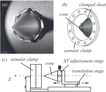
We use annular thin sheets cut out of aluminum foil (Young’s modulus E = 70 GPa, Poisson ratio ν = 0.3, thickness h = 18 µm). The foil is clamped at its outer radius (Rs = 60 mm) with no pretension. A rigid
cone, whose axis is perpendicular to the sheet and in-tersects it at its center is mounted on a translation stage (Fig. 1). The direction of translation coincides with the axis of the cone, which is incrementally (increment size δz = 0.1 mm) pushed to enlarge the initial hole in the sheet. It does so by opening radial cracks. Two cones, with different angles (20 deg and 45 deg) were used lead-ing to the same results. The penetration radius R is mea-sured at the intersection of the cone and the plane of the sheet. The circular inner edge, of radius R0 = 1.5 mm,
prevents the sheet from breaking dynamically at the early stage of the process, as would an intact sheet punctured by the sharp tip of the cone. Thus, the perforation can be considered as quasistatic. We have also performed ex-periments with an imposed initial uniform pattern of n0
cracks, each of initial length 1.5 mm, to study the rear-rangements of the radial cracks network with increasing penetration depth. XY adjustement stage cone translation stage annular clamp Z annular clamp cone clamped sheet (a) (b) (c)
FIG. 1. (a) Picture of the cone perforating the aluminum sheet. (b) Clamped sheet. (c) Sketch of the experimental setup used for perforation.
Figure 2(a) shows the number of cracks obtained with different initial number of cracks n0. The number of
cracks is measured at R = 25 mm and does not change for larger R. For n0 ≤ 4, the number of radial cracks
increases through the initiation of new cracks or branch-ing of the previous ones as shown on Fig. 2(b). The pattern systematically evolves toward a uniform radial cracks network. However, for a few experiments with n0 = 4, the pattern does not expand radially but
spon-taneously starts to rotate to form spiralling cracks [8]. This behavior is not observed for other values of n. For 5 ≤ n0≤ 12, the initial number of cracks is conserved and
we observe uniform patterns of n = n0 cracks expanding
in the radial direction. For larger values of n0(n0≥ 13),
the number of cracks decreases so that n ≤ n0. In that
regime n does not depend on n0and the final number
sys-tematically decreases to n = 10 or n = 11. Figure 2(c) shows how the pattern rearranges from n0= 20 to n = 10
over a few increments δz. With no initial cracks (insert in Fig. 2(a)), the most probable number of cracks is n = 5,
2 5 mm 5 mm 5 mm n0= 3 n0= 20 n0= 0 (b) (c) (d)
(i) (ii) (iii) (iv) (v)
(i) (ii) (iii) (iv) (v)
(i) (ii) (iii) (iv) (v)
n0 0 2 4 6 8 10 12 14 0 5 10 15 20 25n Counts 0 2 4 6 8 10 3 4 5 6 7 8 9 n0= 0 n (a)
FIG. 2. (a) Number of cracks n obtained for different initial numbers n0. At a given n0, the solid lines emphasize the dispersion
of the results. The inserted figure shows the distribution of cracks numbers for n0= 0. (b-d) Evolution of the pattern for (b),
n0= 3; (c), n0= 20; (d), n0 = 0. The penetration depth increases from left to right by steps of 1.5 mm, 2.4 mm and 1 mm for
(b), (c) and (d) respectively. In (d), the arrows point to the cracks and the dashed line arrow shows a crack which does not further expand with increasing penetration depth.
with some dispersion. Figure 2(d) illustrates an experi-ment starting from n0= 0 and leading to a final number
n = 5. Interestingly, we observe the rearrangement of the pattern switching from n = 6 to n = 5 cracks between pictures (ii) and (iii): the dashed line arrow points to a crack for which the local configuration was similar to the case of large n0 and, as a result, this crack did not
further expand.
To compute the strain and stress fields in the sheet as the cone penetrates, we consider that the problem is planar. We neglect bending energy because the thickness of the sheet is small (h/R ∼ 10−3), so that the energy
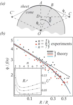
required to fold a petal between two adjacent cracks is negligible [9]. Figure 3(a) shows a schematic of the inner boundary of the sheet, for a uniform pattern of n radial cracks. The initially straight segment [CC�] joining two
crack tips, is stretched to a length equal to 2(AB + BC) as the cone is forced through the sheet. We express the corresponding extensional strain �n in terms of n and φn
the angle between the tangent to the cone and [CC�]
�n=
φncos(π/n − φn) + sin(π/n − φn)
sin(π/n) − 1. (1)
The angle φn, which determines the position of the crack
tips is bounded by two limits: if φn= 0, the crack tips are
localized at maximum distance of the cone and the sheet is stress free (�n = 0); if φn= π/n, the crack tips are in
contact with the cone and then, the strain is maximum (˜�n= (π/n)/ sin(π/n) − 1).
We assume that the sheet is made of a perfect elas-tic material i.e. we neglect plaselas-tic deformation that we consider to be confined to a small area of the mem-brane with a limited effect on the total energy. To
com-pute the stored elastic energy, we replace the complex inner shape of the membrane by a circular edge at ra-dius R with azimuthal strain �n yielding the radial
dis-placement field ζ(r) = RsR2(Rs2−R2)−1(Rs/r−r/Rs)�n
[10]. The strains are �r = ∂ζ/∂r and �θ = ζ/r and the
stresses are given by Hooke’s law. The stress σθ is
posi-tive in the vicinity of the cone, and this tension leads to further extension of the cracks. The stretching energy Ue = πh�(σr�r + σθ�θ)rdr of the annular membrane
clamped at Rs with imposed azimuthal strain �n at R
writes Ue= π� 2 n 1 − ν2 � (1 − ν)R2s R2 + 1 + ν � EhR4 R2 s− R2 . (2)
To predict the crack length, we resort to the celebrated Griffith’s criterion [11]. The energy needed to create new surface δUcmust be balanced by the change of bulk
elas-tic energy stored in the material δUe. The
irreversibil-ity at the microscopic level during crack growth may be taken into account by introducing a fracture energy Γ which embraces the energy required to break material bonds as well as other dissipative processes localized near the crack tip. Increasing crack length by δL thus requires a fracture energy δUc = 2ΓhδL. For δL = nδl, in which
δl is the incremental length of a single crack, Griffith’s criterion takes the form
δU δL = δ(Ue+ Uc) δL = 0 =⇒ δUe δl = −2nΓh. (3) Noticing that δUe/δl = δUe/δφn× δφn/δl, further
ge-ometric considerations provide δφn δl = − tan(π/n − φn) cos(π/n − φn) 1 R, (4)
(a) 2 3 4 5 0.1 0.3 0.5 n = 5 n = 6 n = 7
}
experiments}
theory R / Rs R n U* 0.05 0.1 0.15 0.2 2 3 4 5 6 7 8 f( n) (b) O A B C C’ D n n sheet n coneFIG. 3. (a) Schematic of the deformation of the inner bound-ary of the sheet in contact with the cone between crack tips located in C and C�. The folded petal is not shown. (b) Evo-lution of the angle φn/f (n) with the perforation radius R/Rs.
The solid line stands for the full theoretical prediction and the dotted line represents the approximation of Eq. (7). The dots stand for the measurements. Each experimental point repre-sents the mean value of the 2n angles measured in a n cracks pattern. The inserted figure shows the evolution of the global energy U∗ with cracks number n, computed for penetration radii 2 mm, 4 mm and 6 mm.
the condition on n and φn being
gn(φn) =1 − ν 2 π � Γ ER � R2 s− R2 R2 × � (1 − ν)R2s R2 + 1 + ν �−1 , (5)
in which the function gn writes as
gn(φn) =φnsin(π/n − φn) cos(π/n − φn
) n sin(π/n) tan(π/n− φn)
�n. (6)
This relation, linking the couples (n, φn) to the
ma-terial properties, provides the admissible radial cracks morphologies. A simpler form of condition (5) may be obtained in the limit of R � Rs and φn� π/n. In such
conditions, the asymptotic angle φn writes
φn� f(n) � Γ ER �1/3 , (7) in which f (n) = � 2� 1 + ν π � �n tan(π/n) cos(π/n) � �1/3 . (8)
Experimental measurements of φnare shown on Fig. 3(b)
for several values of n. The adjusted parameter of the theoretical curves is the fracture energy Γ, and the value Γ = 110 kJ.m−2 matching well the experimental data is
also consistent with the order of magnitude observed in other studies of the petalling of thick aluminum plates [12]. Figure 3(b) shows that the prediction of the angle φn is in very good agreement with measurements. In
ad-dition, the approximated formula (7) (dashed line) works well for small penetration radii R, as expected. We em-phasize that the value of the fracture energy Γ obtained above embraces both kind of irreversibilities, namely sur-face creation by crack propagation (the sursur-face energy), and plastic strain work at the cracks tips.
Thus, Griffith’s criterion allows the determination of φn if n is known. To compute the most probable number
of cracks n∗, we minimize the global energy of the system
throughout the perforation process, an approach some-times used to predict crack path in fracture mechanics [13]. Hence, n∗ satisfies ∂ ∂n � 1 R− Rc � R Rc U dR � = ∂U∗ ∂n � � � � n=n∗ = 0 , (9) where Rc is the penetration radius at which cracks
ap-pear. The evolution of U∗ with n is reported in Fig.
3(a). Theory predicts an optimal number of cracks com-prised between n = 4 and n = 5, consistently with the experimental observations reported in Fig. 2.
To understand the dispersion in the final number of cracks, we consider the discrete nature of the problem. When n > n∗, the radial cracks pattern should rearrange
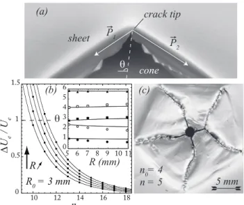
to reduce the number of cracks from n to n − 1 by cross-ing an energy barrier. When a crack stops, in the area of the sheet comprised between the two other adjacent cracks, the strain increases locally to its maximal value as the crack approaches the edge of the cone. Hence the expression of the normalized energy barrier is
∆Ue Ue = ˜�2n− �2n n�2 n . (10)
Since the only energy stored in the system is the elastic energy, the relative energy barrier must satisfy ∆Ue/Ue < 1 in order to allow for cracks number
de-crease. Fig. 4(b) shows the energy barrier predicted by the model. In the range of parameters of our experi-ments, the system is able to spontaneously decrease the number of cracks for n > 10 only, since ∆Ue/Ue > 1
for smaller n. Moreover, the energy barriers tend to be higher for larger R, thus preventing any rearrangement with increasing penetration depth, as experiments show. Therefore, both the prediction of the optimal num-ber of cracks n∗ and the energy gaps criterion offer a
good understanding of the experimental results reported in Fig. 2. In particular, the dispersion of the initial num-ber of cracks n0< 5 can be interpreted as the signature of
4 R R0 = 3 mm n Ue / Ue 0 0.5 1 1.5 10 12 14 16 18 R (mm) 0 1 2 3 4 5 6 5 6 7 8 9 10 11 5 mm n0= 4 n = 5 (c) (b)
(a) crack tip P1
P2
cone
sheet
FIG. 4. (a) Sketch of a crack tip in a random pattern. Two punctual forces �P1,2, tangent to the cone, act on the corner
formed by the crack tip. (b) Evolution of the switching en-ergy with the cracks number n, computed for perforation radii ranging from 10.5 mm to 12.5 mm. The inserted figure shows the evolution of the angular position of the cracks θ (in radi-ans) with the penetration radius R. The dots stand for the measurements and the solid line for the theoretical predic-tions. (c) Post mortem crack path of a perforated aluminum sheet.
initial defects. Indeed, if local imperfections initiate the creation of additional cracks such that n > n∗, although
the energy state of the system is not minimized, high en-ergy gaps prevent the cracks pattern to reach the optimal number of cracks n∗. Nevertheless, for a large number of
initial cracks, the system relaxes to fewer cracks, typi-cally n = 10 in the case of aluminum sheets, as for the other materials we have tested, like paper for instance.
Experiments also show that a random crack distribu-tion systematically evolves toward a regular pattern of cracks expanding radially (with uniform angles). To de-scribe the evolution of the pattern, we refer to the prin-ciple of local symmetry which implies the conservation of the local symmetry around a crack tip during its propaga-tion [14]. The symmetry axis of the stress field around a crack in a random pattern deviates from the radial direc-tion and so does the direcdirec-tion of propagadirec-tion of the crack. We use the solution to the elastic problem of two punc-tual forces acting on a corner [15] to crudely approximate the stress field around a crack tip, see Fig. 4(a). Then, using the principle of local symmetry, we compute the fracture path for a random cracks pattern and compare it to the experiment. Results reported in the inserted graphic of Fig. 4(b) show good agreement between the prediction and observed cracks trajectories. Thus, since randomly distributed cracks spontaneously evolve toward uniformity, the choice of a model focusing on uniform ra-dial cracks patterns is consistent with the observed and
predicted phenomenology.
In conclusion, we have shown that the morphology of the cracks on an indented thin sheet can be described by a simple argument balancing stretching elastic energy and surface energy associated with the cracks extension. Global energy minimization allows to infer the most fa-vorable pattern without relying on the precise descrip-tion of the local features of the cracks. In particular we do not explicitly account for the singular stress field that develops at the tip of the crack, nor on the transi-tion to a plastic behaviour in the sheet. Instead, we use an ad hoc fracture energy determined from the pattern shape, whose value is used to compute its later evolution, and the number of cracks, in quantitative agreement with many features of the experiment. Figure 4(c) epitomizes this fact: starting with 4 cracks, the system switches to 5 cracks by crack branching and immediately starts to globally rearrange to reach the preferred uniform (sym-metrical) state. An obvious extension of this study is to investigate whether those principles help understand-ing the more complex case of the radial cracks patterns in impacted brittle plates–the common broken window case.
∗ Also at: Institut Universitaire de France
[1] N. Shinkai, in Fractography of Glass, edited by R. C. Bradt and R. E. Tressler (Plenum Press (New york), 1994).
[2] J. ˚Astr¨om and J. Timonen, Phys. Rev. Lett. 79, 3684 (1997).
[3] Y. Li and Z. P. Baˇzant, J. Eng. Mech. 120, 1481 (1994). [4] B. Landkof and W. Goldsmith, Int. J. Solids Struct. 21:
3, 245 (1985).
[5] Y. Rhee, H.-W. Kim, Y. Deng, and B. Lawn, J. Am. Ceram. Soc 84, 1066 (2001).
[6] G. Gauthier, V. Lazarus, and L. Pauchard, Europhys. Lett. 89, 26002 (2010).
[7] J. Locke and J. A. Unikowski, Forensic Science Interna-tional 51, 251 (1991).
[8] V. Romero, E. Cerda, and B. Roman (2010), to be sub-mitted.
[9] B. Audoly, P. M. Reis, and B. Roman, Phys. Rev. Lett. 95: 025502 (2005).
[10] G. Lam´e, Le¸cons sur la th´eorie math´ematique de l’´elasticit´e des corps solides (Gauthiers-Villars, Paris, 1866), p. 188.
[11] A. A. Griffith, Philos. Trans. R. Soc. London, Ser. A 221, 163 (1921).
[12] K. Kaminishi, M. Taneda, and S. Tanaka, JSME Int. J. Ser. 1 35: 4 (1992).
[13] G. Francfort and J. Marigo, J. Mech. Phys. Solids 46, 1319 (1998).
[14] R. V. Gol’dstein and R. L. Salganik, Int. J. Fract. 10, 507 (1974).
[15] S. P. Timoshenko and J. N. Goodier, Theory of Elasticity (Third Edition) (McGraw-Hill Editions, 1970).