Content-adaptive lenticular prints
The MIT Faculty has made this article openly available.
Please share
how this access benefits you. Your story matters.
Citation
James Tompkin, Simon Heinzle, Jan Kautz, and Wojciech Matusik.
2013. Content-adaptive lenticular prints. ACM Trans. Graph. 32, 4,
Article 133 (July 2013), 10 pages.
As Published
http://dx.doi.org/10.1145/2461912.2462011
Publisher
Association for Computing Machinery (ACM)
Version
Author's final manuscript
Citable link
http://hdl.handle.net/1721.1/90390
Terms of Use
Creative Commons Attribution-Noncommercial-Share Alike
Content-adaptive Lenticular Prints
James Tompkin
Disney Research/MPI f¨ur Informatik
Simon Heinzle Disney Research Zurich
Jan Kautz
University College London
Wojciech Matusik MIT CSAIL
Simulated view 1
Horizontal light field slice Horizontal light field slice
Close-up view Simulated view 1 Close-up view
Lens surface Image plane Lens surface Image surface Profile photo Profile photo
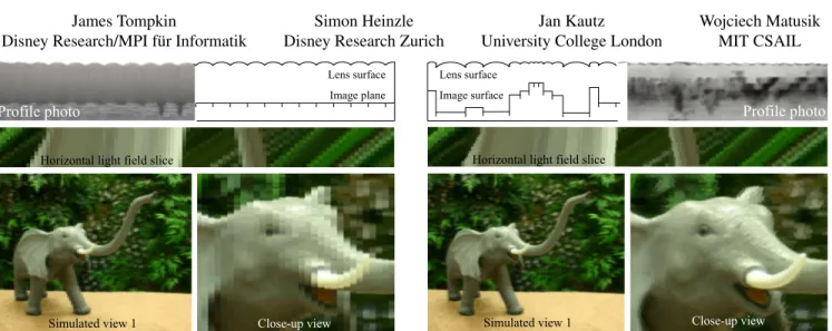
Figure 1: We exploit the varying frequency content of static light fields to optimally adapt lenslet array display patterns. Top: Two lenticular displays, printed with a multi-material printer. Left: Regular lenticular, with lens sizes chosen to maximize PSNR of the input light field. Right: Content adaptive lenticular, where our optimization process distributes a set of lenses based on a local frequency analysis of the light field. The resulting light field emitted from our display is crisper than that from a regular lenticular display, exhibits much smoother motion parallax, and results in a higher PSNR.Bottom: A slice from the emitted light fields and two simulated views.
Abstract
Lenticular prints are a popular medium for producing automulti-scopic glasses-free 3D images. The light field emitted by such prints has a fixed spatial and angular resolution. We increase both perceived angular and spatial resolution by modifying the lenslet array to better match the content of a given light field. Our opti-mization algorithm analyzes the input light field and computes an optimal lenslet size, shape, and arrangement that best matches the input light field given a set of output parameters. The resulting emitted light field shows higher detail and smoother motion paral-lax compared to fixed-size lens arrays. We demonstrate our tech-nique using rendered simulations and by 3D printing lens arrays, and we validate our approach in simulation with a user study.
CR Categories: I.3.1 [Computer Graphics]: Hardware Architec-ture —Three-dimensional displays;
Keywords: Lenticular displays, 3D printing.
Links: DL PDF WEB
1
Introduction
Displays that provide the illusion of three dimensions have recently experienced a rebirth. While most commercial displays rely on spe-cial glasses, it is generally agreed that automultiscopic displays — displays able to provide 3D vision without glasses — offer signifi-cant advantages. The predominant automultiscopic technology to-day is based on parallax-type displays, which create the illusion of three dimensions by physically separating emitted viewing rays. Ray separation is often achieved by placing tiny lens arrays in front of an image surface. This lenticular technology is well suited to display 3D content in uncontrolled lighting environments, in con-trast to other techniques such multi-layer or holographic displays [Lueder 2012]. Lenticular arrays have constant pitch and are ar-ranged on a regular grid to accommodate the maximum possible depth. However, three dimensional scenes often do not cover all depth ranges throughout the scene, and local patches of the scene might be better represented using different lens arrangements. We introduce content-adaptive lenticular prints: a method for static displays which uses a modified lens array optimized to a static input light field. Our approach is motivated by the observation that light fields generated from real world scenes often show locally-varying angular and spatial frequency content. Therefore, a regular lenticu-lar arrangement using one type of lens often cannot reproduce such light fields efficiently, and parts of these light fields could be rep-resented better using different lens sizes and arrangements if we could exploit the varying frequency content.
We achieve this by computing an optimal arrangement of different lens sizes based on an analysis of the input light field. Our discrete optimization algorithm distributes a precomputed set of lenslets ac-cording to the angular and spatial frequencies of the input light field to generate a lenticular print with improved angular and spatial res-olution over regular samplings. To maximize vertical spatial reso-lution, our algorithm supports 1D horizontal parallax which is suffi-cient to support stereoscopic viewing. In addition to the distribution algorithm, we determine an optimal set of input lenses given
spe-cific manufacturing limits. Further, we employ additive 3D multi-material printing technology to manufacture physical prototypes of the proposed content-adaptive lenslets. Using 3D printing, we are able to introduce general-purpose lenticular display features such as view-blockers using baffles, non-planar image surfaces, and ori-ented lenses for better field of view usage. We demonstrate the im-proved reproduction quality with simulated results as well as with proof-of-concept physical prototypes.
Our contributions are:
• A light field analysis and optimization strategy to yield the ideal layout of 1D lenslets which trades between spatial and angular resolution for a given static scene.
• Optimized lenses for 3D-printing automultiscopic displays. • 3D-printed prototypes of content-adaptive lenticular displays.
2
Related Work
Autostereoscopic and multi-view display technology has been ex-tensively researched, and continues to be a prominent research field. Lueder [2012] presents a recent overview on the huge body of re-lated work. We focus on lenticular displays for integral imaging, parallax barrier type displays, and multi-layer light field displays. Integral Imaging Lippmann [1908] proposed a small array of lenticular lenses to acquire an incident light field onto a film plane, a process being revived currently in so-called light field cameras. The same film plane with the same lenses forms a 3D display that emits the captured light field. Many improvements to Lippmann’s basic idea have been proposed, and a thorough overview of recent advances is given Kim et al. [2010]. For instance, apparent reso-lution can be enhanced by using slanted lenticular sheets arranged with respect to LCD subpixels [Berkel 1999] or by spatio-temporal multiplexing [Jang and Javidi 2002]. Kim et al. [2005] demonstrate curved lenticulars for wider viewing angles, whereas Takahashi et al. [2006] propose holographic lens elements to increase field of view. Park et al. [2005] propose using two layers of lenslets with different sizes and focal lengths to increase the number of possible rays. Said and Talvala [2009] propose a multi-projector system to improve quality. In contrast, Fuchs et al. [2008] present a regular lenticular display system which additionally relies on the incident illumination angles to support ambient lighting-dependent effects. Ueda et al. [2008] propose an adaptive integral imaging camera sys-tem using programmable lenses which can individually change their field of view. Kao et al. [2009] present a display that changes the focal length of all lenses simultaneously to adapt to the viewer’s distance. Jang and Javidi [2003] present an acquisition and display system where multiple lenses with different focal lengths and aper-tures in a fixed, semi-regular lenslet array are interleaved in space and time by rapid movement. Kim et al. [2011] present a similar acquisition system using a fixed, stationary, semi-regular lenslet ar-ray, which could also be used for integral image displays. Both strategies increase resolution and depth of field; however, the lens arrangement is not optimized for a given scene and therefore sub-optimal. To our knowledge, no related works have tried to find an optimal spatial/angular resolution trade-off for a given light field. Parallax Barriers Ives [1903] proposed one of the first parallax barrier multi-view displays, where a blocking pattern in front of a image surface provides different views for different viewing an-gles. Using LCD technology, Isono et al. [1993] proposed a dy-namic parallax barrier to adapt the barrier pattern based on the num-ber of users and their positions. Time-multiplexed parallax barriers [Kim et al. 2007] can improve the perceived spatial sampling res-olution. Stereoscopic content can be adapted to the viewer’s
po-sition by tracking their location [Perlin et al. 2000; Peterka et al. 2008]. The Random Hole Display [Nashel and Fuchs 2009] ran-domizes the barrier pattern, replacing interference between views with high frequency noise which is visually less objectionable. The displays of Cossairt et al. [2007] and Jones et al. [2007] show a 360◦light field of a scene. While termed volumetric displays, they are similar to parallax barrier displays. Instead of using a block-ing pattern to direct different rays to different angles, the content is time-multiplexed onto a rotating mirror with a high-speed projector. Holography Holography [Schnars and J¨upter 2005; Zebra Imag-ing 2013] uses the interference of two laser beams to record a light field. While holography can produce excellent results, there are clear limitations. Holograms require a point light positioned at a specific location to reproduce the light field. Due to relatively high light absorption, the point light needs to be very bright compared to the environment lighting. This makes holograms difficult to use outdoors. In contrast, lenticular technology can use reflected light and backlighting at much better light efficiency, making it easier to use in uncontrolled environments with area lights.
Multi-layer Light Field Displays Lanman et al. [2010] improve on parallax barrier displays by using modulation instead of block-ing barriers. The modulation pattern is dynamically adapted based on a factorization of the light field, which results in higher reso-lution and brightness when compared to traditional parallax barrier approaches. Wetzstein et al. [2011] extend this approach to multiple modulating layers, where the layer contents are computed using to-mographic reconstruction techniques. The layered display is able to reproduce a very high spatial resolution with good ranges of depth. Lanman et al. [2011] reformulate the problem to switching LCDs instead of modulating layers and show a real-time prototype using multiple stacked LCD screens. Holroyd et al. [2011] present a re-lated multi-layer display based on blocking display layers instead of modulating ones. Wetzstein et al. [2012] propose a general frame-work for displays comprising time-multiplexed, light-attenuating layers illuminated by uniform or directional backlighting. The main advantage is reduced artifacts and wider field of views than previ-ous multi-layer displays. While not a light field display, Sajadi et al. [2012] use multi-layer LCDs and an optical pixel sharing unit in a projection system to provide resolution enhancement.
Light Field Analysis Chai et al. [2000] presented the first analy-sis on the sampling requirements for light field signals, and Durand et al. [2005] extended their work to a fundamental analysis of light transport and its sampling requirements. Based on both analyses, Zwicker et al. [2006; 2007] determine the limits of light field dis-plays and introduce effective anti-aliasing strategies. One of the basic findings of their work is the trade-off between spatial and an-gular resolution, on which our optimization is based. This analysis was later extended to include aliasing on light field displays in the presence of visual crosstalk [Jain and Konrad 2007; Ramachandra et al. 2011], where a sharpening pre-filter was proposed to reduce the effects. Hachisuka et al. [2008] introduced optimized adap-tive sampling strategies for light field generation using raytracing. Lehtinen et al. [2011] exploit preceding light field analysis to ef-ficiently and adaptively sample and reconstruct multi-dimensional signals in ray-tracing. Our light field analysis differs as our goal is to determine the best angular and spatial resolution trade-off. Lens Design and Printed Optics While a broad body of work for lens-system design exists [Smith 2007], few papers focus on the optimal design of lenses for automultiscopic viewing: Johnson and Jacobsen [2005] discuss lenticular sheet manufacturing tech-nologies and propose elliptically-shaped lenses to reduce cross-talk. Micro lenses has been successfully printed using an approach simi-lar to ink-jet printing (e.g., see [Cox et al. 2001; Cruz-Campa et al.
high angular,
low spatial resolution Light field sampling pattern
Light field sampling pattern low angular,
high spatial resolution
s s spatial support s u s u u u angular support f FOV
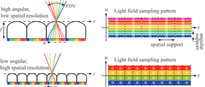
Figure 2: Left: Lenticular lens array. Different viewing directions are multiplexed to different pixels on the image plane, creating an automultiscopic display. Right: The (s, u) sampling pattern of the lenslet array (2D light field). The width of the lens defines its extent in the spatial(s) domain. The focal length f and width define the field of view of the lens, which in turn defines the angular(u) sup-port. The angular sampling pattern becomes denser when traded against spatial resolution with a constant field of view. The u sam-ples are defined relative to their associated s sample.
2010], where small droplets are dispersed onto a substrate). How-ever, these technologies generate a tiny lens for each droplet and are not applicable to larger lenses. To our knowledge, bigger lenses have not been manufactured using printing technology. Very re-cently, Willis et al. [2012] print embedded custom optical elements to achieve interactive devices that are 3D printed in their entirety. Our approach extends their vision by augmenting printed devices with stereo display capabilities. Papas et al. also extend their opti-mization techniques for goal-based caustics [2011] to handle con-figurations of planar refractive surfaces for magic lenses [2012].
3
Lenticular Displays
We summarize the principle of automultiscopic displays based on lenticular arrays, and for this we assume that each lens can be mod-eled as a perfect pinhole. Figure 2 shows one line of such a display: different viewing directions are angularly multiplexed through the lens and are mapped to different pixels on the image plane. An ob-server at some distance from the lens array will see different pixels for different positions along the horizontal axis and will perceive motion parallax as well as stereoscopic depth cues.
Following the notation of Zwicker et al. [2006], the lens array emits an output light field that can be characterized by a spatial and angu-lar pattern (s, u) (Figure 2). The anguangu-lar sampling points are defined relative to their respective spatial sampling points. In other words, sdenotes the origin of the ray, whereas u describes the direction of the emitted ray, such that each lens defines a spatial sampling loca-tion and emits multiple angular samples from the image plane. The spatial sampling density is defined by the lens width, whereas the angular sampling density is characterized by the focal length f and the underlying pixel density. Each column in the (s, u) plot denotes one lens, and each row denotes a set of parallel rays.
The exact sampling densities can be arbitrary, but are often bound by the possible resolution of the image surface as well as the opti-cal qualities of the employed lenses. Figure 2 shows two different configurations, assuming a constant image surface density and a constant field of view. Increasing the width of individual lenses in-creases the number of angular samples and, subsequently, supports more angular variation. Increased angular resolution comes at the cost of reduced spatial resolution, which is a fundamental trade-off for current lenticular and parallax-barrier based displays.
Low spatial, high angular
{
{
Input scene`
EPI (line 192)
u
s
High spatial, low angular High spatial, low angular
{
Figure 3: The local angular and spatial frequency content of light fields often differs considerably.Top: Three frames of a scene. The background wall is positioned approximately at the focal plane of the display, and the two apples float in front of the focal plane. Bot-tom: The frequencies for one line of the input light field (red line in input images) shown in epipolar plane image (EPI) representation. The angular frequencies of the wall are very low, whereas its spa-tial frequencies are very high. In contrast, the red apple features high angular frequencies and low spatial frequencies.
4
Content-adaptive Lenticular Displays
All current lenticular displays are based on regular (s, u) sampling patterns. However, the local angular and spatial frequencies of nat-ural light fields often differ considerably, and many of the (s, u) samples are either wasted or not optimally placed for a given light field. Figure 3 shows an example where a textured wall is located at the focal plane. As a result, the angular frequency content of each point on the wall is low (all viewing directions see the same color), but the spatial frequency content is high (the wall is textured). The objects in front of the plane require much less spatial frequency and much more angular frequency due to their distance from the display. This insight motivates our approach: while objects close to the fo-cal plane would ideally have lenses with low angular variation (i.e., lens width of one pixel), objects further away from the focal plane would benefit from larger lenses. Therefore, we propose to locally adjust the lenses to better replicate the input light field. We achieve this by distributing lenses of varying size in conjunction with opti-mizing the image pattern such that the light field emitted from the display generates the least error compared to the input light field. 4.1 Discrete Light Field Optimization
Our goal is to find a lens distribution that generates an output light field `outwhich matches an input light field `inas close as possible:
Lo= arg min L
(norm(`in, `out(L))), (1)
where Lo= {li|i = 1..n} denotes the optimal lens distribution, and
norm() can be any appropriate norm (e.g., L2 or gradient based). Each lens li= {wi, ci, pi} is characterized by its width wi, the color
content of the image surface ci, and the lens parameters pisuch as
the focal length. The field of view of all lenses and the resolution of the color content are kept constant across the whole display. As a result, the angular resolution of a lens increases with its width wi.
Solving for the optimal distribution given a discrete set of lenses is a packing problem, similar to the knapsack problem. However, in our case, the weights are not known a priori as each lens will result in a different error depending on its placement. Therefore, we propose a bottom-up dynamic programming approach to find an optimal dis-tribution Lofor an input light field `in, where our algorithm
recur-sively determines the best lens configuration for larger and larger subsets of `in. In each recursion step, we place all lenses from the
Algorithm 1: e = computeLensDistribution(`in)
for all possible candidate lenses li
// Compute error for placing lens lion right-hand side of`in
ei= error(li∩ `in)
// Add lowest possible error for remainder of `in
ei= ei+ computeLensDistribution(`in\ li)
return lens liwith lowest error ei
set of candidate lenses at the right-hand side of the input light field and compute the error (Equation 1) over their extent. Then, our goal is to find the lens distribution which minimizes the error for the remaining left-hand side of the input light field. We recurse, and perform the same procedure on the remaining left-hand side subset of the light field not covered by the initial lens placement. The re-cursion continues until the width of the remaining left-hand side is equal to the smallest candidate lens. The error induced by the final lens placement is propagated up and at each stage of recursion the lens arrangement with the lowest error is selected. The memoiza-tion step in our dynamic programming algorithm is the storage of the error sums and corresponding lens distributions for the left-hand side recursion widths. As we solve for horizontal parallax only, our algorithm can be evaluated independently on single scanlines. Al-gorithm 1 summarizes our optimization; more detailed pseudocode and an example run are given in the supplemental material. The error that a lens incurs follows the same metric as defined in Equation 1, but it is computed only over the subset of the light field covered by the lens. Therefore, Algorithm 1 will provide an opti-mal solution for Equation 1. Our optimization employs an L2 error norm: the squared difference between input and output ray colors defines the error for a given lens at a given position. Perceptual norms in other color spaces are possible, however, we found our results were convincing without further comparison.
Resampling and Filtering Figure 2 shows that each lens covers a number of spatial and angular samples from the input light field. These need to be resampled to the spatial-angular pixel samples of the lens. We use a box filter according to the output sampling width, so each pixel on the image surface is computed from the mean color of the input rays covered by each output sample. From a signal processing point of view, better filters would be more ap-propriate; however, only approximate filters could be used due to our irregular sampling structure, such as elliptical weighted aver-age (EWA) filters or splatted filters (e.g., Lanczos). These depend on the output sampling pattern in a larger neighborhood and would ideally be applied once the output is given. Of course, the specific output is unknown until after optimization. It is possible to filter for every possible lens combination, or at optimization time, but this is computationally expensive.
To speed up the optimization, we further resample the input light field to the maximum output resolution using bicubic resampling. Therefore only one interpolation step is carried out before starting the optimization, rather interpolating for each candidate lens. Spatial vs. Angular Weighting The L2 error can be computed directly in the light field domain; however, the angular and spatial dimensions can be re-weighted if desired. Instead of computing a 2D box filter, we compute the angular and spatial errors individu-ally: the L2 norm is computed along the spatial direction (summing up 1D box columns) and the angular direction (summing up 1D box rows). The resulting errors are combined using a spatial-angular weighting factor, which steers the lens generation between repro-ducing angular and spatial variation. All our results were computed with equal weights for both dimensions, as a balanced weighting subjectively produces the best results. The supplemental material shows examples of spatial-angular weighting factor variation.
Spherical lens Aspherical lens Aspherical lens Aspherical lens Axis aligned patches Linear patches
MSE = 0.084 MSE = 0.064 MSE = 0.053 MSE = 0.051
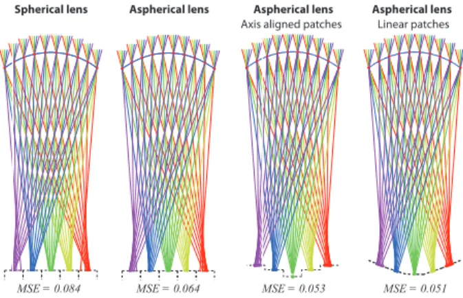
Figure 4: Raytraces through our optimized lenses, shown for a 30◦ field of view and a5mm width. Each color corresponds to a set of orthographic rays; the image surface is shown beneath. Our opti-mization minimizes the mean squared projection error to the pixel center. Aspherical lenses show better off-axis characteristics, and with arbitrary image surfaces the error can be minimized further. Multi-scanline Solves Our algorithm computes the optimal lens distribution for each scanline individually, which can lead to spatial noise along otherwise crisp edges. This can be mitigated by choos-ing similar lenses in neighborchoos-ing scanlines. To this end, we extend our algorithm such that a sliding window of multiple scanlines is used to compute the lens arrangement for each particular scanline. The lens error on one scanline is then computed by summing the er-rors supposing the lens were also applied to neighboring scanlines in a window. This gives an increase in smoothness but a reduction in apparent resolution, for additional computational cost (Figure 7). Algorithmic Complexity Our optimization algorithm requires O(kLkn) space complexity as well as O(kLkn) run-time complex-ity for a scanline width of n pixels and a set of candidate lenses L, where kLk is typically less than 20. In comparison, the (exhaustive) search space is of similar size to the restricted integer partition func-tion, which is of exponential order [Hardy and Ramanujan 1918]. 4.2 Lens Optimization
To generate the desired lens arrangement from our discrete opti-mization, an appropriate set of candidate lenses must be determined before the full display can be generated. Given a minimum lens size and target display resolution, we first optimize for lenses of the desired widths. Our optimization searches for 1D plano-convex aspherical lenses that result in the best focusing quality across all views for a given overall field of view.
While analytical solutions for minimizing spherical aberration for the central views exist [Kweon and Kim 2007], yielding similar solutions for multiple off-center views is tedious to achieve, espe-cially if coma aberrations are also to be minimized. Instead, we employ numerical optimization to generate the optimal lens shape given a specific lens model. More specifically, we strive to mini-mize the deviation of the refracted viewing rays from their ideal fo-cus position. This deviation is computed by raytracing through the parameterized lens surface and intersecting the refracted rays with the pixel surface. The deviation error is then defined as the sum of squared distances of the intersection points to their intended pixel center. A non-linear optimization minimizes this focus error for the parameterized lens model. We investigated two different lens types: spherical lenses and aspherical lenses. In general, aspherical lenses tend to be superior to spherical lenses, especially for center views [Johnson and Jacobsen 2005]. The result of a numerical
optimiza-Diffuse backing
Current self-aligned 3D fabrication (c)
Backlight Multi-step alignment or future 3D print technologies
Correct view across FOV (b)
Adhered 2D printed
Incorrect views (a)
Figure 5: Fabrication alternatives. Aligned image planes across all lenses might lead to incorrect views (a). By aligning the lenses onto a plane these inconsistent views can be eliminated (b). Our current printing technology allows to print only two materials simultaneously. While one material is being used for the clear lens shape, we print varying thicknesses of a black material to achieve different shades of gray. tion for a 5mm lens with a 30◦field of view can be found in Figure
4, where we show ray-traces of both lens models and the associated average focus errors (normalized to the pixel size) from five ortho-graphic viewing directions. More details on the lens optimization can be found in the supplemental material.
Since our fabrication procedure is quite flexible (Section 5) we pro-pose two optimizations: to adapt the shape of the image surface, and to rotate lenses towards the primary viewing location. Non-Planar Image Surface The optimal focusing distance for different views does not lie on a plane but rather on a curved sur-face [Smith 2007], and ideally the image plane should be at a dif-ferent depth for difdif-ferent views. We incorporated alternative image plane shapes into our optimization: axis-aligned planar patches, non-axis aligned facets and parametric curves. In addition to the lens model parameters, the optimization includes parameters for the pixel heights in the case of axis-aligned patches or vertex points in the case of linear patches. Thus, the shape of the lens as well as the back surface are optimized jointly. In general, the views close to the optical axis of the lenses can be improved greatly by this op-timization, whereas the off-axis views tend to perform similarly to the initial optimization result. Figure 4 shows the result of this opti-mization for aspherical lenses for axis-aligned and non-axis aligned facets. As can be seen from our optimization results, the resulting focus error can be reduced by 17.5% and 20.8% respectively for a material with index of refraction n = 1.47.
Lens Rotation Using lenses with aligned optical axes wastes many rays on the borders of the lenslet array that will fall outside the combined field of view of all lenses. Due to the lens characteris-tic for off-axis views, lenses on the array borders will further show increased crosstalk. To minimize these effects, we align the optical axis to the expected center position of the viewer. More specifically, the amount of rotation for each lens is chosen such that all optical axes intersect at the center position for an assumed viewer distance.
5
Fabrication
Lenticular prints usually consist of a regular lens sheet with a printed image glued underneath (Figure 5a). The lenticular sheet is usually composed of optical quality plastic resin and is typically created by extruding plastic underneath a drum shaped with the in-verse of the required lens profile [Johnson and Jacobsen 2005]. Af-fixing the image to the lens requires pixel-accurate registration for the light field to appear correctly. As our lens arrays change shape and position over the image, existing lenticular fabrication methods are less practical. It is possible to manufacture a drum or mold to create the correct lens array shape but, as this shape changes with each input light field, it may only be economical for large print runs. With the advent of high-accuracy 3D printing technology, our work becomes more applicable and accessible. We employ an additive multi-material printer that fabricates 16µm-accurate object layers using uv-curable resin (Objet500 Connex 3D polymer printer). As our printer is able to print two different materials simultaneously,
we chose to fabricate the lens surface simultaneously with the im-age surface rather than using separately printed cards. Furthermore, 3D printing also easily allows for lenses with non-planar image sur-faces. Printing the lenses and the display simultaneously means that our image surface is perfectly aligned with the lens surface. In-stead of producing one image surface for all lenses (shown in Figure 5a), which would introduce visual artifacts throughout the field of view of the display, we align the lens surfaces rather than the im-age planes to remove the crosstalk from adjacent lenses of different sizes (Figure 5b). With this approach, there are no artifacts within the field of view of the display, but beyond it the backlight will leak through these discontinuities unless baffles are printed.
A limitation of our current printer is that it is only able to print two materials at the same time. As the first material, we use a trans-parent resin to realize the lens shape, and we use the other mate-rial to print the display content. We choose a black matemate-rial for the display content. Since the cured black resin is translucent at lower thicknesses, we can vary the thickness of the resin to display shades of gray. Prior to printing, we perform a color to grayscale conversion that improves the contrast by preserving visual saliency [Gooch et al. 2005]. Figure 5c illustrates this concept. While we are currently limited to grayscale values, we anticipate that future 3D printers will support many colors, thus enabling colored content-adaptive lenticular prints. As a work around for our current printer, we could employ a multi-step printing process: in a first step, the lenses with non-regular image planes could be manufactured. Then, on a separate multi-color 3D printer, an image surface with colored pixels could be fabricated. Finally, the colored pixel surfaces could be combined onto the lens shape. If approximated color is suffi-cient, a simple trick can be applied to our gray-scale prints: the (color) input light field is filtered according to the lens distribu-tion, normalized in intensity, and positioned behind the lenticular print, either on a transparency in front of the backlight or on an LCD display (which acts as a spatially-varying colored backlight). While the color plane does not coincide with the focus plane at many points, the results still show approximated color.
Lens Precision Current 3D printers have severe resolution lim-itations for printed optics. The smallest possible pixel and lens sizes we achieved for an Objet500 Connex 3D polymer printer were 0.2mm and 1mm respectively, though we achieved more reliable re-sults with 0.5mm pixels and 2.5mm+ lenses: small lenses that are malformed can cause refracted rays to pass through the gaps in the image plane, causing bright spot highlights from the backlight. We successfully avoid this by printing larger lenses.
Field-of-view Baffles We print baffles between scanlines to stop light leaking through the non-planar image surface when the view-ing position is far from vertically parallel. Due to the translucency of current materials and printer minimum feature sizes (0.2mm), the baffles give an appearance similar to ‘black scanline’ CRT mon-itors; however, printer manufacturers continue to reduce this limit and improve materials. Once printers support multiple colors, it might be possible to print content onto baffles, adding the challenge of designing a lens to focus well on both image plane and baffle.
Irregular9lens9/9varying thickness9of9back9pattern Non-planar9display9surface Regular9lens9/9varying thickness9of9back9pattern Lens9surface Lens9surface Lens9surface Back9pattern 15mm 15mm 9mm image
Figure 6: Irregular structure, non-planar image surfaces, and varying pixel thickness for grayscale prints. Left: 15mm; 1mm to 2mm lenses.Middle: 15mm; 3mm lenses. Right: 9mm; 3mm lenses.
Single line solve 9-scanline solve
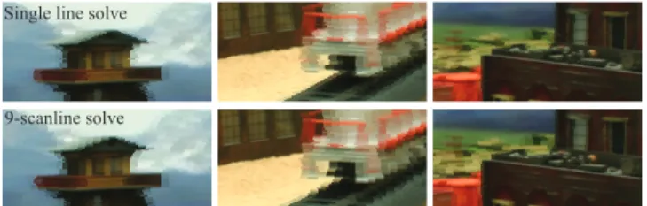
Figure 7: Effect of the multi-scanline approach for one example. The noisy streak artifacts can be reduced when solving across mul-tiple lines, however at the cost of reducing the apparent resolution. 5.1 Discussion
While a perfectly shaped and manufactured aspherical lens will not support arbitrary dense display pixels due to its coma and spheri-cal aberration, 20 pixels are realizable from a 10mm aspherispheri-cal lens with a field of view of 30◦. Furthermore, for perfectly shaped lenses the number of pixels that can be optically resolved is independent from the lens width, as long as the field of view remains constant. However, manufactured lenses are never perfect. Due to manufac-turing limits, smaller lenses show higher noise and inaccuracies, which restricts the smallest possible pixel and lens size. In this case, our adaptive approach can improve the printed result. This holds es-pecially true for the Objet500 Connex printer: although resolutions of up to 16µm of layer thickness are possible, the resulting lens shape is still inaccurate and therefore rather large lenses and image surfaces are needed. We anticipate that the resolution of future 3D printers will increase and this will allow for smaller lenses. We currently require backlighting to achieve grayscale values. The different depths of black material refract light slightly differently, and lenses will inadvertently image different (out of focus) portions of multiple stacks of neighboring pixels. Even so, we do not believe this is a limiting factor in our prototypes as the lens size is much bigger than the difference in refraction direction. With future multi-material printers, an opaque colored image plane could be printed directly to fully avoid this problem.
While our printed results are promising, 3D printers still need to improve before being able to compete with the quality of PMMA molded lenticulars. Nevertheless, our approach shows potential and might be embedded and combined with other printed optics ap-proaches [Willis et al. 2012]. We hope that our research into printed optics will stimulate discussion and spur 3D printer manufacturers to improve printer resolution and concurrent material range.
6
Results
We evaluate our algorithm using both simulation and physical pro-totype prints. Our test light fields show a wide variety of
differ-ent scenes, from low to high detail, with objects showing diffuse, specular, and transparency effects. We perform simulations assum-ing a perfect pinhole lens model as well as ray traces of our op-timized lenses. Figure 10 shows the simulated perfect pinhole re-sults compared to various regular lenslet arrays. Furthermore, Fig-ure 10 shows results using ray tracing through the generated lens surface which exhibit crosstalk due to optical aberrations. The sim-ulations were performed using one refractive index only and thus chromatic aberrations are neglected. Our adaptive lens arrays im-prove the perceived spatial and angular resolution simultaneously when compared to regular lens arrays. Most significantly, object borders appear much crisper due to the implicit error adaption of our algorithm. Due to the irregular arrangement of the lenses, alias-ing artifacts are less noticeable at the cost of some noisy areas. To quantify the error improvement, we include PSNR comparisons be-tween the input and output light fields in Table 1. As our algorithm computes an optimal sampling with the L2 norm, and is free to fall back to regular sampling strategies, the PSNR will always be at least as high as the best regular sampling. In our scenes, we see that our adaptive sampling improves PSNR over regular samplings. Our approach works best for complex scenes, as such scenes can well hide the irregular lens alignment. For less complex scenes, the irregular alignment becomes more obvious, especially for round structures. Nevertheless, the perceived motion parallax is much smoother than using a regular lens distribution, which may be due to the semi-irregular sampling structure. The perceived ‘streak’ ar-tifacts, most visible at high-contrast edges, can be reduced using the multi-scanline optimization, and Figure 7 shows this with reduced spatial noise. However, locally enforcing a regular structure reduces apparent parallax and spatial resolution. High-contrast edges are difficult to handle even with multi-scanline solving, which cannot remove all artifacts due to the angular/spatial trade-off.
To complement PSNR evaluations, we conducted a user study to perceptually assess our approach (Table 2). The study presents 10 pairwise comparisons between our content-adaptive lenslets and the highest-PSNR-ranked regular lenticular version. Our user study as-sessed 34 participants, most with a computer science background. The participants were asked “Which video do you prefer? Please assess both sharpness and motion smoothness (spatial resolution and angular resolution).” An introduction explained how preference is selected in the experiment. In general, the participants signifi-cantly favored our results. However, two of the scenes (‘necklace’ and ‘tarot fine’) exhibited noisy streak artifacts, and participants were split as to which choice was preferred. In cases such as these with high specularity or refraction, we cannot conclude from our study on the aliasing vs. noise trade-off. However, in other cases, our content-adaptive lenslet approach is able to increase the per-ceived angular and spatial resolution.
Figures 1, 6, and 9 show our prototype prints. The train scene has an input light field 1146×473 pixels large with 100 views. The physical print is 490×202mm large. The light field is optimized for a 30◦ FOV, with pixels 0.5×2.5mm large, and lenses ranging from 1mm to 12.5mm in width with the added option of placing no lens at all in pixel-sized widths. Across all scanlines, the mean lens width is 3.4mm with a std. dev. of 2.0mm, and lenses from 1mm to 7.5mm are represented (including no lens). The thickness of the print is mostly defined by the focal length of the largest lens, plus some small amount for the deepest black-level content thickness (2.1mm). With a 7.5mm largest lens, the print is 22mm thick total. The elephant scene has an input light field 634×680 pixels large with 100 views. The physical print is 300×322mm large. The light field is optimized for a 30◦FOV, with pixels 0.4×2.5mm large, us-ing the same set of lenses as before. Across all scanlines, the mean lens width is 6.3mm with a std. dev. of 1.9mm, and all possible
Sampling Amethyst Elephant Foyer Jelly Beans Lecture Lego Bulldozer Lego Knights
Mansion Necklace Pomme Tarot Coarse Tarot Fine Train Input views 17 100 150 17 150 17 17 101 17 256 17 17 100 Adaptive 31.51 24.10 30.59 35.05 28.43 26.59 26.13 18.21 19.04 33.71 22.10 26.27 26.81 Reg. 2 views 30.33 21.07 28.03 31.29 25.26 24.28 22.99 15.96 18.47 29.69 19.46 24.61 24.00 Reg. 5 views 31.42 22.64 29.61 34.76 27.87 25.89 25.90 17.39 18.09 31.43 21.66 25.23 25.72 Reg. 10 views 27.89 23.65 29.24 32.93 27.17 23.86 24.52 17.56 18.12 31.27 21.23 22.94 24.40
Reg. 20 views N/A 22.63 27.28 N/A 24.95 N/A N/A 16.67 N/A 29.97 N/A N/A 22.01
Table 1: PSNR (dB) for input light fields against various regular samplings and our content-adaptive sampling (with no lens simulation). The adaptive sampling has between 2 and 50 views, though if there are fewer input views (say, 17), then we limit to this number.
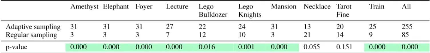
Amethyst Elephant Foyer Lecture Lego
Bulldozer Lego Knights
Mansion Necklace Tarot Fine
Train All
Adaptive sampling 31 31 31 27 22 24 31 13 20 25 255
Regular sampling 3 3 3 7 12 10 3 21 14 9 85
p-value 0.000 0.000 0.000 0.000 0.016 0.001 0.000 0.055 0.151 0.000 0.000
Table 2: User study results for preference of our adaptive sampling or the regular sampling with the best PSNR. Computed using Mann-Whitney U-tests at the 5% significance level. Green marks statistical significance, where a low p-value denotes high significance.
Volumetric Barrier Multi-layer Hologram Lenticular Adapt. Lent. Print proto.
Spatial Res. High Low High High High Low Optimal Optimal
Angular Res. High Moderate High High Low High trade-off and low
Brightness High Low Mod→High Moderate High High Moderate
Contrast Moderate Moderate High Moderate Moderate Moderate Moderate
FOV Wide Moderate Narrow Wide High High High
Complexity High Low Moderate High Low Moderate Moderate
Flip Anim. No Yes Low res. Yes Yes No No
Outdoors Yes Maybe Maybe No Yes Yes Yes
Table 3: Method categorization, including a hypothetical best-case adaptive lenticular fabrication method and our printed prototypes.
lens widths are represented (including no lens). The thickness of the print with a 12.5mm largest lens is 29mm. The difference in lens choice (and so thickness) shows that, even though both light fields have the same number of input views, there is more variation in angular content appearance within the elephant scene.
The optimization and simulation framework is implemented in Mat-lab. The discrete optimization for 13 candidate lenses (widths be-tween 1 and 25 pixels) can be computed in approximately 2 minutes for 1916×1272 display pixels (image surface), where 12 scanlines are computed in parallel. Due to the recursive structure of our algo-rithm, we expect large speedups with a native implementation. The 3D printing requires approximately 10 hours. Unfortunately, the 3D printer software cannot cope with our high resolution meshes for a full print and so we split the displays into multiple tiled strips. 6.1 Discussion and Future Work
Table 3 compares content-adaptive lenticulars to other light field display techniques (following Wetzstein et al. [2011]). Volumetric displays are complex and involve moving mechanical parts [Cos-sairt et al. 2007; Jones et al. 2007]. Parallax barrier displays can only offer low resolution and reduce brightness. Multi-layered dis-plays [Wetzstein et al. 2011; Lanman et al. 2011] offer a good spa-tial and angular resolution, but depicting high spaspa-tial frequencies at high contrast over a large field-of-view is difficult. Further, layered displays require a certain thickness to achieve good results. Holog-raphy [Schnars and J¨upter 2005] can achieve impressive results, but requires controlled lighting and cannot be used outdoors. Stan-dard lenticular lenses suffer from either low spatial or low angular resolution, as discussed previously. In principle, content-adaptive lenticulars offer a versatile solution and are particularly well suited
to display static 3D content in uncontrolled lighting environments, which is required for advertisements.
Our adaptive lenticulars achieve a low but balanced spatial and an-gular resolution, albeit in a scene-dependent manner. Brightness and contrast are similar to standard lenticular prints – at least once printing technology supports multiple colors. The supported FOV is higher than has been demonstrated in multi-layered displays. Flip animations are possible, but our adaptive approach will simply de-generate to a standard lenticular array.
Our method is limited to static content. Ideally, our approach would be combined with a display that is able to shape the lens of the lenticular on the fly in order to display dynamic content. In fact, electronically tunable LC lenses have the potential to dynamically adapt the lens arrangements, but this is future work. Furthermore, we are only supporting horizontal parallax for the following rea-sons. First, we can compute a global optimal solution, whereas the 2D lens packing problem is NP hard and computing a global optimum is challenging or even impossible. Second, 2D lenticular prints trade even more spatial resolution for angular, and would re-duce the quality of the results. Fortunately, horizontal parallax is sufficient for stereoscopic viewing and horizontal head motion. Current printing technology is not advanced enough to produce high-quality lenticular prints, but future printing technology, e.g., two-photon microfabrication [Sun and Kawata 2004], will likely be able to print higher-resolution lenses. For higher accuracy pro-ductions, a photo-lithographic process on silicon wafers [Wu et al. 2002] could be used as well, but the alignment of the printed surface would then have to be achieved in a second step.
7
Conclusion
We introduced content-adaptive lenticular prints. We jointly op-timize both the lens configuration and the static light field con-tent, and achieve apparent increases in spatial and angular resolu-tion. Our simulations show improved PSNR compared to regular samplings. Participants in a user study significantly favor content-adaptive samplings. While current 3D printing techniques inhibit high-quality color results, advances in printing technology will im-prove the quality of our prototype lenticular prints.
Figure 8: All input light fields used for our experiments. Please see the accompanying video for results.
Figure 9: Printed results for the elephant (gray and approximated color) and train data set (gray). The areas of different spatial and angular resolution are clearly visible in these prototype displays. While there are still manufacturing issues related to current printing technology, the varying lens surface is demonstrated.
Acknowledgements Light fields courtesy of UCSD/MERL Light Field Repository,The (New) Stanford Light Field Archive, andDisney Research Zurich [Kim et al. 2013]. Thanks to Moira Forberg, Shinjiro Sueda, Samuel Muff, Pitchaya Sitthi-amorn, Nate Derbinsky, Kiril Vidimˇce, Bernd Bickel, our study participants, and the Intel Visual Computing Institute.
References
BERKEL, C. V. 1999. Image preparation for 3D-LCD. Proc. SPIE Stereoscopic Displays and Virtual Reality Systems 3639, 84–91. CHAI, J.-X., TONG, X., CHAN, S.-C.,ANDSHUM, H.-Y. 2000.
Plenoptic sampling. In Proc. SIGGRAPH, 307–318.
COSSAIRT, O. S., NAPOLI, J., HILL, S. L., DORVAL, R. K.,AND
FAVALORA, G. E. 2007. Occlusion-capable multiview volumet-ric three-dimensional display. Applied Optics 46, 1244–1250. COX, W. R., CHEN, T.,ANDHAYES, D. J. 2001. Micro-optics
fabrication by ink-jet printers. Optics and Photonics News 12, 6, 32–35.
CRUZ-CAMPA, J. L., OKANDAN, M. O., BUSSE, M. L., AND
NIELSON, G. N. 2010. Microlens rapid prototyping technique with capability for wide variation in lens diameter and focal length. Microelectronic Engineering 87, 11.
DURAND, F., HOLZSCHUCH, N., SOLER, C., CHAN, E., AND
SILLION, F. X. 2005. A frequency analysis of light transport. ACM Trans. Graph. (Proc. SIGGRAPH) 24, 1115–1126. FUCHS, M., RASKAR, R., SEIDEL, H.-P.,ANDLENSCH, H. P. A.
2008. Towards passive 6d reflectance field displays. ACM Trans. Graph. (Proc. SIGGRAPH) 27, 3, 58:1–58:8.
GOOCH, A. A., OLSEN, S. C., TUMBLIN, J., ANDGOOCH, B. 2005. Color2gray: salience-preserving color removal. ACM Trans. Graph. (Proc. SIGGRAPH) 24, 3, 634–639.
HACHISUKA, T., JAROSZ, W., WEISTROFFER, R. P., DALE, K., HUMPHREYS, G., ZWICKER, M.,ANDJENSEN, H. W. 2008. Multidimensional adaptive sampling and reconstruction for ray tracing. ACM Trans. Graph. (Proc. SIGGRAPH) 27, 3, 33:1– 33:10.
HARDY, G. H.,ANDRAMANUJAN, S. 1918. Asymptotic formulae in combinatorial analysis. In Proc. London Math. Soc., vol. 17, 75–115.
HOLROYD, M., BARAN, I., LAWRENCE, J.,ANDMATUSIK, W. 2011. Computing and fabricating multilayer models. ACM Trans. Graph. (Proc. SIGGRAPH Asia) 30, 6, 187:1–187:8. ISONO, H., YASUDA, M.,ANDSASAZAWA, H. 1993.
Autostereo-scopic 3-D display using LCD-generated parallax barrier. Elec-tronics and Communications in Japan 76, 7, 77–84.
IVES, F., 1903. Parallax stereogram and process for making same. U.S. Patent No. 725,567.
JAIN, A.,ANDKONRAD, J. 2007. Crosstalk in automultiscopic 3-D displays: blessing in disguise? Proc. SPIE Stereoscopic Displays and Virtual Reality Systems 6490, 649012.
JANG, J.-S.,ANDJAVIDI, B. 2002. Improved viewing resolution of three-dimensional integral imaging by use of nonstationary micro-optics. Optics Letters 27, 5, 324–326.
JANG, J.-S., AND JAVIDI, B. 2003. Large depth-of-focus time-multiplexed three-dimensional integral imaging by use of lenslets with nonuniform focal lengths and aperture sizes. Op-tics Letters 28, 1924–1926.
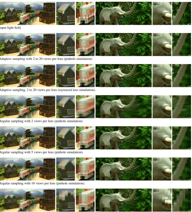
Input light field.
Adaptive sampling with 2 to 20 views per lens (pinhole simulation).
Adaptive sampling, 2 to 20 views per lens (raytraced lens simulation).
Regular sampling with 2 views per lens (pinhole simulation).
Regular sampling with 5 views per lens (pinhole simulation).
Regular sampling with 10 views per lens (pinhole simulation).
Regular sampling with 20 views per lens (pinhole simulation).
Figure 10: Spatial and angular resolution variation for the train and elephant test scenes, with the front of the house set to be at zero depth (‘on’ the resulting lenticular display) in the train scene and the tusk similarly in the elephant scene. The first close up shows spatial resolution improvements on the house and face, while the second shows angular improvements on the train and trunk. For regular samplings, the train scene has highest PSNR at 5 views while the elephant scene has highest PSNR at 10 views. Our supplemental material has more results.
JOHNSON, R. B., ANDJACOBSEN, G. A. 2005. Advances in lenticular lens arrays for visual display. In Proc. SPIE 5874. JONES, A., MCDOWALL, I., YAMADA, H., BOLAS, M., AND
DEBEVEC, P. 2007. Rendering for an interactive 360 light field display. ACM Trans. Graph. 26, 3, 40:1–40:10.
KAO, Y.-Y., HUANG, Y.-P., YANG, K.-X., CHAO, P. C.-P., TSAI, C.-C., AND MO, C.-N. 2009. An auto-stereoscopic 3D display using tunable liquid crystal lens array that mimics effects of GRIN lenticular lens array. SID Symposium Digest of Technical Papers 40, 111–114.
KIM, Y., PARK, J.-H., MIN, S.-W., JUNG, S., CHOI, H.,AND
LEE, B. 2005. Wide-viewing-angle integral three-dimensional imaging system by curving a screen and a lens array. Applied Optics 44, 546–552.
KIM, Y., KIM, J., KANG, J.-M., JUNG, J.-H., CHOI, H., ,AND
LEE, B. 2007. Point light source integral imaging with improved resolution and viewing angle by the use of electrically movable pinhole array. Optics Express 15, 26, 18253–18267.
KIM, Y., HONG, K.,ANDLEE, B. 2010. Recent researches based on integral imaging display method. 3D Research 1, 17–27. KIM, S.-C., KIM, C.-K., AND KIM, E.-S. 2011.
Depth-of-focus and resolution-enhanced three-dimensional integral imag-ing with non-uniform lenslets and intermediate-view reconstruc-tion technique. 3D Research 2, 2, 6.
KIM, C., ZIMMER, H., PRITCH, Y., SORKINE-HORNUNG, A.,
ANDGROSS, M. 2013. Scene reconstruction from high spatio-angular resolution light fields. To appear ACM Trans. Graph. (Proc. SIGGRAPH).
KWEON, G.-I.,ANDKIM, C.-H. 2007. Aspherical lens design by using a numerical analysis. Journal of the Korean Physical Society 51, 1, 93–103.
LANMAN, D., HIRSCH, M., KIM, Y.,ANDRASKAR, R. 2010. Content-adaptive parallax barriers: optimizing dual-layer 3D displays using low-rank light field factorization. ACM Trans. Graph. (Proc. SIGGRAPH) 29, 6, 163:1–163:10.
LANMAN, D., WETZSTEIN, G., HIRSCH, M., HEIDRICH, W.,
ANDRASKAR, R. 2011. Polarization fields: dynamic light field display using multi-layer LCDs. ACM Trans. Graph. (Proc. SIG-GRAPH) 30, 6 (Dec.), 186:1–186:10.
LEHTINEN, J., AILA, T., CHEN, J., LAINE, S., ANDDURAND, F. 2011. Temporal light field reconstruction for rendering dis-tribution effects. ACM Trans. Graph. (Proc. SIGGRAPH) 30, 4, 55:1–55:12.
LIPPMANN, G. M. 1908. La photographie integrale. Comptes-Rendus 146, 446–451.
LUEDER, E. 2012. 3D Displays. Wiley.
NASHEL, A., ANDFUCHS, H. 2009. Random Hole Display: A non-uniform barrier autostereoscopic display. In 3DTV Confer-ence: The True Vision – Capture, Transmission and Display of 3D Video, 1–4.
PAPAS, M., JAROSZ, W., JAKOB, W., RUSINKIEWICZ, S., MA
-TUSIK, W., AND WEYRICH, T. 2011. Goal-based caustics. Computer Graphics Forum 30, 2, 503–511.
PAPAS, M., HOUIT, T., NOWROUZEZAHRAI, D., GROSS, M.,
ANDJAROSZ, W. 2012. The magic lens: Refractive steganogra-phy. ACM Trans. Graph. (Proc. SIGGRAPH Asia) 31, 6, 186:1– 186:10.
PARK, J.-H., KIM, J., KIM, Y.,ANDLEE, B. 2005. Resolution-enhanced three-dimension / two-dimension convertible display based on integral imaging. Optics Express 13, 1875–1884. PERLIN, K., PAXIA, S.,ANDKOLLIN, J. S. 2000. An
autostereo-scopic display. In Proc. of SIGGRAPH, 319–326.
PETERKA, T., KOOIMA, R. L., SANDIN, D. J., JOHNSON, A., LEIGH, J., ANDDEFANTI, T. A. 2008. Advances in the dy-nallax solid-state dynamic parallax barrier autostereoscopic vi-sualization display system. IEEE T. VIS. COMPUT. GR. 14, 3, 487–499.
RAMACHANDRA, V., HIRAKAWA, K., ZWICKER, M., AND
NGUYEN, T. 2011. Spatio-angular prefiltering for multiview 3D displays. IEEE T. VIS. COMPUT. GR. 17, 5, 642–654. SAID, A.,ANDTALVALA, E.-V. 2009. Spatial-angular analysis of
displays for reproduction of light fields. Proc. SPIE 7237. SAJADI, B., GOPI, M.,ANDMAJUMDER, A. 2012. Edge-guided
resolution enhancement in projectors via optical pixel sharing. ACM Trans. Graph. 31, 4 (July), 79:1–79:122.
SCHNARS, U.,ANDJ ¨UPTER, W. 2005. Digital Holography: Dig-ital Hologram Recording, Numerical Reconstruction, and Re-lated Techniques. Springer.
SMITH, W. J. 2007. Modern optical engineering. SPIE Press. SUN, H.-B.,ANDKAWATA, S., 2004. Two-photon
photopolymer-ization and 3d lithographic microfabrication.
TAKAHASHI, H., FUJINAMI, H.,ANDYAMADA, K. 2006. Wide-viewing-angle three-dimensional display system using hoe lens array. Proc. SPIE 6055, 60551C–1–60551C–9.
UEDA, K., KOIKE, T., TAKAHASHI, K., AND NAEMURA, T. 2008. Adaptive integral photography imaging with variable-focus lens array. Proc. SPIE 6803.
WETZSTEIN, G., LANMAN, D., HEIDRICH, W.,ANDRASKAR, R. 2011. Layered 3D: Tomographic image synthesis for attenuation-based light field and high dynamic range displays. ACM Trans. Graph. (Proc. SIGGRAPH) 30, 4, 95:1–95:12. WETZSTEIN, G., LANMAN, D., HIRSCH, M.,ANDRASKAR, R.
2012. Tensor displays: Compressive light field synthesis using multilayer displays with directional backlighting. ACM Trans. Graph. (Proc. SIGGRAPH) 31, 4, 80:1–80:11.
WILLIS, K., BROCKMEYER, E., HUDSON, S.,ANDPOUPYREV, I. 2012. Printed optics: 3d printing of embedded optical ele-ments for interactive devices. In ACM Symposium on User In-terface Software and Technology, 589–598.
WU, M.-H., PARK, C.,ANDWHITESIDES, G. 2002. Fabrication of arrays of microlenses with controlled profiles using gray-scale microlens projection photolithography. Langmuir 18, 24. ZEBRA IMAGING, 2013. ZScape digital holographic prints.R
http://www.zebraimaging.com.
ZWICKER, W., MATUSIK, W., DUR, F., PFISTER, H., ZWICKER, M., MATUSIK, W., DURAND, F.,ANDPFISTER, H. 2006. An-tialiasing for automultiscopic 3D displays. In Eurographics Sym-posium on Rendering, 73–82.
ZWICKER, M., VETRO, A., YEA, S., MATUSIK, W., PFISTER, H., ANDDURAND, F. 2007. Resampling, antialiasing, and compression in multiview 3-D displays. IEEE Signal Processing Magazine 24, 6 (Nov.), 88–96.