Received: November 2013 Alexandros TERZIS: Dr. Eng.
www.springerlink.com DOI: 10.1007/s11630-014-0692-8 Article ID: 1003-2169(2014)02-0169-08
A Comparative Study of the Local Heat Transfer Distributions Around Various
Surface Mounted Obstacles
Robert Wyssmann, Dirk Ullmer, Alexandros Terzis
*, Peter Ott
Group of Thermal Turbomachinery (GTT), École Polytechnique Fédérale de Lausanne (EPFL) SCI-STI-PO, CH-1015, Lausanne, Switzerland
© Science Press and Institute of Engineering Thermophysics, CAS and Springer-Verlag Berlin Heidelberg 2014
In many engineering applications, heat transfer enhancement techniques are of vital importance in order to ensure reliable thermal designs of convective heat transfer applications. This study examines experimentally the heat transfer characteristics on the base plate around various surface mounted obstacles. Local convection coefficients are evaluated in the vicinity of each individual protruding body with great spatial resolution using the transient liquid crystal technique. Five different obstacles of constant height-to-hydraulic diameter ratio (~1.3) are consid-ered. These include: a cylinder, a square, a triangle, a diamond and a vortex generator of delta wing shape design. The experiments were carried out over a range of freestream Reynolds numbers, based on the hydraulic diameter of each obstacle, varying from 4,000 to 13,000. The results indicate a negligible effect of the flow speed on the heat transfer topological structure and a considerable effect of the obstacle geometry on the level and distribution of heat transfer enhancement.
Keywords: surface obstacles, heat transfer enhancement, transient liquid crystal technique Introduction
Convective heat transfer is widely applicable over a range of engineering applications for reasons of thermal management, as for example the cooling of electronic equipment and turbine airfoils. However, the continu-ously raised heat fluxes increase the operational tem-peratures in various heat exchanger applications, requir-ing heat transfer enhancement techniques in order to en-sure reliability of thermal designs.
Three dimensional surface mounted obstacles are a particularly attractive heat transfer enhancement tech-nique by inducing secondary flows which increase the turbulence levels produced at the wake of the body gen-erating an intense flow mixing. Heat transfer associated with flow over arrays of various fin shapes, mainly used
for gas turbine cooling applications, has been the sub-ject of extensive research, e.g. Ligrani et al. [1], Han et al. [2], Chyu et al. [3], Metzger et al. [4], Chang et al. [5], while a recent review can be found in the study of Li-grani [6]. However, for the design of optimal cooling configurations it is crucial to understand the local nature of the surface heat transfer. Therefore, there are several studies dealing with heat transfer characteristics around single surface mounted elements, such as cylinder (Spar-row et al. [7], Goldstein et. al [8], Chyu and Natarajan [9], Giordano et al. [10]), square (Igarashi [11], Meinders et al. [12], Chyu and Natarajan [9]), triangle (Zeitoun et al. [13]) and diamonds (Chyu and Natarajan [9], Tanda [14]). Despite the huge amount of sources for local heat trans-fer distributions around single surface obstacles, com-parative studies for different protruding bodies are lim-
H m obstacle height μ kg/(m s) dynamic viscosity
k W/(m K) thermal conductivity
Re - Reynolds number Subscripts
t s time i initial conditions
T K temperature ∞ freestream conditions
U m/s velocity g hot gas conditions
VG vortex generator LC liquid crystals
x,y,z coordinate system ref flat plate (no obstacle)
ited in the literature.
The objective of the present study is to examine ex-perimentally the heat transfer characteristics in the vicin-ity of individual obstacle with great spatial resolution using the transient liquid crystal technique, and to com-pare the achievable heat transfer enhancement. Five ob-stacles, which are typically found in gas turbine blade cooling applications are considered. These include: (1) cylinder, (2) square, (3) triangle, (4) diamond and (5) a delta wing shape vortex generator, similar to Henze et al. [15]. The experiments were carried out over a range of Reynolds numbers, based on the hydraulic diameter of each obstacle, varying between 4,000 and 13,000. The results of the present study may provide useful informa-tion for thermal designers for array arrangements involv-ing multiple elements as well as their optimum installa-tion for augmented heat transfer areas.
Test Facility and Surface Obstacles
The test facility is illustrated in Figure 1. The open circuit wind tunnel consists of a two stage axial flow fan, a bellmouth transition piece, a straight section of square ducting that contains an air heater and the test section where the obstacles are mounted on the base surface of a flat plate. The test section consists of a rectangular flow path of 100×100 (mm)2 and the flat plate is coated with
liquid crystals in order to visualize the surface tempera-
ture of the generated flow domain upstream and down- stream of each obstacle. The flow conditions were deter-mined by the Reynolds number based on the hydraulic diameter of each obstacle (d), as follows:
Red U d
(1) where U∞ is the freestream velocity measured with a thermal anemometer upstream of the heater grid and μ is the dynamic viscosity of air calculated at hot conditions (heater mesh in operation). The uncertainty in the deter-mination of Reynolds number was less than 2%.
Basic requirement for a transient experiment is a sud-den change in the mainstream temperature which in this study is achieved with a heater grid which is able to in-crease the temperature of the flow to the required level in less than 0.2s using Joule heating. Electric power to the heater is supplied through a 5 kW DC-Power supply. The evolution of the liquid crystal color on the flat plate is recorded with a high definition RGB camera (AVT Pike F210C) connected to a computer with a frame grabber. Therefore, great spatial resolution is obtained revealing detailed information for the heat transfer distribution. The typical spatial resolution is approximately 20 pix-els/(mm)2 and the recorded video data are digitized at
15fps.
Figure 2 presents a schematic representation of the surface obstacles considered in this study. The five ob-stacles are: (1) a cylinder, (2) a square, (3) an equilateral
Fig. 2 Geometrical details of the three dimensional obstacles. H/α=1.3. H=0.02m
triangle, (4) a diamond and (5) a vortex generator of delta wing shape. The obstacles are manufactured of plastic material with similar thermal properties as the base plate in order to maintain the heat transfer distribution in their vicinity unaffected. For all the bodies, the obstacle height-to-side ratio is constant at 1.33. The hydraulic diameters for the cylinder, the square, the triangle, the diamond and the vortex generator is 15mm, 15mm, 12.35mm, 15mm and 18.35mm, respectively.
Data reduction
Transient liquid crystal technique
The main principle of this technique is to create a sudden change in the mainstream temperature and record the evolution of the surface temperature using thermo-chromic liquid crystals (TLC). Knowing the detection time of liquid crystals (tLC) on a pixel size level, local heat transfer coefficients can be determined from the solution of the 1D Fourier’s transient heat conduction equation, as follows: 2 1 exp LC LC i LC g i h t T T h t erfc T T ck ck (2)
where ρck are the model material thermal properties, Ti and Tg are the initial and hot gas temperature and h is the heat transfer coefficient. Figure 3 indicates a typical temperature step as acquired from different thermocou-ples in the test section. It can be observed that there is no temperature drop through the length of the plate, and therefore, the average value of all the thermocouples was used for the post processing. Note also that the tempera-ture step was fast enough compared to the first liquid crystal appearance time (~7s), and hence, no correction for Duhamel’s principle or thermocouple thermal inertia
Fig. 3 Step change in the mainstream temperature
as proposed by Terzis et al. [16] was applied. For the evaluation of heat transfer coefficients the maximum green intensity of liquid crystals was followed, similar to Poser et al. [17], with an indication temperature of 36.7oC. Within the temperature range used in this study
the lateral conduction error was less than 2% according to Kingsley-Rowe and Owen [18].
Uncertainty analysis
Table 1 indicates the random uncertainty levels of the measured parameters and their individual error propaga-tion on the heat transfer coefficient calculapropaga-tion for two difference cases, a typical low-90 W/(m2K) and a
high-300 W/(m2K) heat transfer coefficient. For the
perature acquisition this was ±0.12K for the initial tem-perature, ±0.23K for the hot gas temperature and ±0.12K for the liquid crystal isotherm. These values correspond to approximately 1.66%, 1.86% and 1.95% uncertainty level in the calculation of the heat transfer coefficient. Note that the flow temperature measurements indicate a slightly increased uncertainty level for the heated flow similar to Hoefler et al. [19]. The contribution of model thermal properties on the total uncertainty is independent of the heat transfer coefficient and remains constant at 5%. The error caused by the detection time of liquid crystals is increased at low tLC indicating that increased heat transfer coefficients are calculated with higher un-certainties. However, given the high sampling rates used for temperature and image acquisition (total error ±0.12s) it is always below 3%. For all geometries over the full range of flow conditions, the total local uncertainty var-ies between 8% and 15% and the area averaged uncer-tainty level from 9 to 12%.
Table 1 Experimental uncertainties
Parameters Low h High h
h W/(m2K) Values 90 300 Ti oC 22.8 ±0.12 1.66 1.66 Tg oC 52.3 ±0.23 1.86 1.86 TLC oC 36.7 ±0.12 1.95 1.95 ρck kgs5/2/K 576 ±29 5.00 5.00 10 0.15 - tLC s 2 ±0.12 - 2.25 Total Uncertainty 10.6% 12.7%
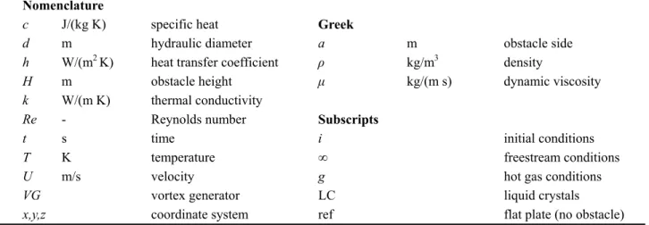
contours for all the obstacles at Red=5000 and 11000, respectively. The results are normalized with the corre- sponding heat transfer obtained for a flow over a flat plate in the absence of any protruding body providing directly a heat transfer enhancement factor. By analyzing the heat transfer contours the flow topology becomes clear, since the horseshoe vortex, flow separation zones and reattachment zones are evident. Additionally, Figures 4 and 5, indicate that there is no actual effect of Reynolds number on the flow topology as a direct consequence of the almost identical heat transfer enhancement pattern.
For the cylinder, as expected a horseshoe vortex is developed on the base plate which enhances the heat transfer upstream and around the obstacle. The formation and dynamics of the horseshoe vortex are well described by Praisner and Smith [20]. As the flow passes the cylin- der, the adverse pressure gradient causes the boundary layer to separate. This results in the formation of a recir- culation zone in the immediate wake of each obstacle
the obstacle and the intensity of the separated flow from the tip of the cylinder which impinges on the base plate. Note also that the reattachment zone is stretched out in the axial direction due to the interaction of the main and separated flows.
For the square prism the heat transfer distribution is very similar with the cylindrical one and a horseshoe vortex sweeps downstream along the two sides of the body. The horseshoe vortex here is stronger and wider compared to the cylindrical obstacle. However, small heat transfer enhancement is observed at the wake of the body. According to Chyu and Natarajan [9] this could be attributed to the sharp-edged geometry and the flat fron- tal configuration which forces flow separation directly on the upstream square corners. As for all bluff bodies, a recirculation zone is formed directly downstream of the square body followed by a turbulent wake where local heat transfer values increased due to flow reattachment.
In the case of an equilateral triangular obstacle, the absence of a stagnation region of flow impingement on
the leading edge, has a negative influence on the horse-shoe vortex heat transfer enhancement, whose effects are minimal compared to the cylindrical and square configu-rations. However, the most important attribute for the flow around the triangular prism is that the peak of heat transfer enhancement is shifted further downstream from the obstacle’s trailing edge. This could be attributed to the upward and downward flow direction guided by the 60deg angle of the leading edge point which slightly de-lays the reattachment of the flow at the wake. Therefore, one can say that for the triangular prism, almost all heat transfer enhancement takes place at the turbulent wake. Similar results observed also by Zeitoun et al. [13]. Di-rectly downstream of the triangular body, the flow sepa-ration is followed by the usual recirculation zone in which the endwall heat transfer enhancement is consid-erably lower compared to the cylindrical and the square prisms.
For the diamond protruding body, upstream of the ob-stacle the distribution of heat transfer is similar to the triangle, however, the horseshoe vortex is stronger and wider. This is attributed to the right angle of the facing point of the diamond which is 30deg higher compared to the triangle, and hence, the frontal area is increased. Ad-ditionally, the influence of the body, on the wake endwall heat transfer is larger compared to the other obstacles due to the larger blockage of the flow. This is in agreement with the results of Yan et al. [21]. The flow separation region directly downstream of the body is similar in size with the triangular body while the heat transfer level on the reattachment point is considerably larger compared to the cylinder and the square but less than the equilateral triangle.
The complex vortex shedding and its effect on the heat transfer enhancement for delta wing vortex generators are well documented by Henze et al. [15, 22]. As for any bluff body fixed on an endwall, a horseshoe vortex is appearing upstream of the delta wing which enhances the heat transfer. However, the level of heat transfer is con-siderably lower compared to any of the other protruding bodies. This is attributed to the relatively small angle of the body’s leading edge, which is 30deg. Additionally, two counter-rotating longitudinal vortices are induced at the obstacle’s leading edge leading to a down flow region behind the vortex generator where the heat transfer is locally increased due to the impingement of the flow at the immediate wake. Therefore, no recirculation region is observed downstream of the vortex generator. At the trailing edge of the obstacle, a structure of heat transfer enhancement with four branches is identifiable. The most pronounced heat transfer areas are induced by the main contra-rotating longitudinal vortices and reach far down-stream positions. The other two heat transfer enhance-ment branches are quickly disappeared and no further
effect on the heat transfer level can be seen. Note that all these observations are consistent with Henze et al. [15]. Comparison of wake heat transfer
Figure 6 indicates a quantitative comparison of the lo-cal heat transfer enhancement at the wake of each
Fig. 6 Local transfer enhancement at various downstream
Due to the independency of the flow structure with Rey-nolds number, only the results for Red=8000 are pre-sented.
At the immediate wake (x/d=0), the maximum local heat transfer enhancement is observed at the positions where the two branches of the horseshoe vortex appear. This indicate values of 2.3, 2.1, 2 and 1.75 for the cylin-der, the diamond, the square and the triangle. Addition-ally, a region of very low endwall heat transfer is ob-served close to the centerline of the base plate due to the recirculation of the flow, shown also in Figures 4 and 5. Note that for the square and the triangular prisms there is no heat transfer enhancement at all since h/href is below unity within ±5mm from the plate centerline.
Slightly downstream of the trailing edge of the bodies (x/d=0.5), as expected heat transfer enhancement is higher for the vortex generator reaching the number of 2.5 in the regions of the two contra-rotating longitudinal vortices. For the other obstacles, the peaks in heat trans-fer are generally decreased by around 20% as a direct consequence of the weaker horseshoe vortex intensity in this region. However, for the diamond shape whose horseshoe vortex is wider and longer, the peaks of en-hancement are maintained at about 1.8 providing good heat exchange capabilities.
At further downstream positions, x/d=2-4, the reat-tachment zone is approached which increase the local heat transfer for the protruding bodies. However, for the vortex generator (not a protruding body), the absence of a reattachment zone reduces the peaks of heat transfer which are also diverged between them following the pat-tern of the longitudinal vortices. For the other bodies, the strength of the reattachment zone in order is triangle, diamond, cylinder and square with heat transfer en-hancement factors of 2.5, 2, 1.8 and 1.5 respectively.
At x/d=8, heat transfer enhancement for all the bodies is around 1.5 in the centerline of the base surface indi-cating a small influence of the body shape on the heat transfer level and distribution. Finally, note that for all the obstacles, close to the spanwise edges of the plate (±30mm), heat transfer enhancement is around unity which indicates that the influence of all the bodies on the heat transfer pattern is negligible.
Area averaged heat transfer enhancement
Figure 7 shows the area averaged heat transfer en-hancement as a function of Reynolds numbers for all the obstacles. These values correspond to an area of interest of three and six hydraulic diameters in front and behind
heat transfer enhancement with increasing Reynolds number. The maximum heat transfer enhancement is ob-served for the diamond and the triangular shape obstacle. This is attributed to the intense reattachment zones and increased heat transfer levels in the wake of these bodies. For both obstacles, h/ href decreases from about 1.4 to 1.3 as Red is increased from 5000 to 11000. For the cy-lindrical and the square prisms, the stronger horseshoe vortex observed in the surface contours (see Figures 4 and 5) is not able to compensate the reduced heat transfer levels at the wake of the bodies, and thus, the overall enhancement capabilities are about 6% lower compared to the obstacles with a triangular leading edge. For the vortex generator, h/ href is considerably lower decreas-ing from about 1.1 to 1.05 over the same flow conditions. This is attributed to the relatively weak horseshoe vortex and the absence of a reattachment zone at the wake of the body. Although the two longitudinal vortices reach far downstream positions (see Figures 4 and 5), they are not able to maintain high levels of heat transfer enhancement.
Fig. 7 Area averagedh/ href against Reynolds numbers Concluding Remarks
In this study, local heat transfer distributions around different obstacles were evaluated using the transient liquid crystal technique. Five different bodies, whose shapes are frequently found in gas turbine cooling appli-cations, were used. These included a cylinder, a square, an equilateral triangle, a diamond and a delta wing shape vortex generator. Local heat transfer enhancement for each individual obstacle were obtained by comparing the results with a pure flat plate.
For all the obstacles a horseshoe vortex is swept up-stream and around the bodies. The intensity of the heat transfer enhancement on the horseshoe vortex in order is: square, cylinder, diamond, triangle and vortex generator. Additionally, at the wake of the bodies a reattachment zone is generated where the local heat transfer rates are
more significant. The strength of reattachment zone in terms of heat transfer enhancement in order is: triangle, diamond, cylinder, square and vortex generator. For the vortex generator the generated down flow increases lo-cally the heat transfer at the immediate wake and two longitudinal vortices starting from the leading edge of the body increase the heat transfer enhancement at far down-stream positions. For the area averaged heat transfer en-hancement (h/ href ) and over a well-defined area of in-terest, highest values are observed for the obstacles with a triangular leading edge (triangle and diamond). For the cylindrical and the square prisms the heat transfer en-hancement level was similar but about 7% lower com-pared to the other shapes. The vortex generator shows considerably lower convective capabilities with about 12% lower h/ href from the cylindrical obstacle. For all the bodies, h/ href was reduced by about 4% over the full range of flow conditions. Finally, the heat transfer pattern, and hence the flow topological structure, is in-dependent of the flow speed within the range of exam-ined Reynolds numbers.
The results of the present study may provide useful information for thermal designers of array arrangements involving multiple elements as well as their position for augmented heat transfer areas.
Acknowledgements
The authors acknowledge the support of Prof. Bern-hard Weigand and Prof. Jens von Wolfersdorf from Uni-versity of Stuttgart, Germany.
References
[1] Ligrani, P., M.M. Oliveira, and T. Blaskovich,
Comparison of heat transfer augmentation techniques.
AIAA Journal, 2003. 41(3): p. 337362.
[2] Han, J.-C., S. Dutta, and S.V. Ekkad, Heat transfer and
pressure drop in blade cooling channels with turbulence promoters. NACA CR-3837, 1984.
[3] Chyu, M.K., V. Natarajan, and Y.C. Hsing, Convective
Heat Transfer of Cubic Fin Arrays in a Narrow Channel.
Journal of Turbomachinery, 1998. 120(2): p. 362367. [4] Metzger, D.E., C.S. Fan, and S.W. Haley, Effects of Pin
Shape and Array Orientation on Heat Transfer and Pressure Loss in Pin Fin Arrays. Journal of Engineering
for Gas Turbines and Power, 1984. 106(1): p. 252257. [5] Chang, S.W., T.L. Yang, C.C. Huang, K.F. Chiang.,
Endwall heat transfer and pressure drop in rectangular channels with attached and detached circular pin-fin array. International Journal of Heat and Mass Transfer,
2008. 51(21–22): p. 52475259.
[6] Ligrani, P., Heat Transfer Augmentation Technologies for Internal Cooling of Turbine Components of Gas Turbine Engines. International Journal of Rotating Machinery,
Article ID 275653, 2013. 2013: p. 32 pages.
[7] Sparrow, E.M., T.J. Stahl, and P. Traub, Heat transfer
adjacent to the attached end of a cylinder in crossflow.
International Journal of Heat and Mass Transfer, 1984. 27(2): p. 233242.
[8] Goldstein, R.J., S.Y. Yoo, and M.K. Chung, Convective
mass transfer from a square cylinder and its base plate.
International Journal of Heat and Mass Transfer, 1990. 33(1): p. 918.
[9] Chyu, M.K. and V. Natarajan, Heat transfer on the base
of threedimensional protruding elements. International
Journal of Heat and Mass Transfer, 1996. 39(14): p. 29252935.
[10] Giordano, R., A. Ianiro, T. Astarita, G.M. Carlomagno,
Flow field and heat transfer on the base surface of a finite circular cylinder in crossflow. Applied Thermal
Engineering, 2012. 49(0): p. 7988.
[11] Igarashi, T., Local heat transfer from a square prism to
an airstream. International Journal of Heat and Mass
Transfer, 1986. 29(5): p. 777784.
[12] Meinders, E.R., T.H. Van Der Meer, and K. Hanjalic,
Local convective heat transfer from an array of wall-mounted cubes. International Journal of Heat and
Mass Transfer, 1998. 41(2): p. 335346.
[13] Zeitoun, O., M. Ali, and A. Nuhait, Convective heat
transfer around a triangular cylinder in an air cross flow.
International Journal of Thermal Sciences, 2011. 50(9): p. 16851697.
[14] Tanda, G., Heat transfer and pressure drop in a
rectangular channel with diamond-shaped elements.
International Journal of Heat and Mass Transfer, 2001. 44(18): p. 35293541.
[15] Henze, M., J. von Wolfersdorf, B. Weigand, C.F., Dietz, S.O. Neumann, Flow and heat transfer characteristics
behind vortex generators – A benchmark dataset.
International Journal of Heat and Fluid Flow, 2011. 32(1): p. 318328.
[16] Terzis, A., J. von Wolfersdorf, B. Weigand, P. Ott,
Thermocouple Thermal Inertia Effects on Impingement Heat Transfer Experiments Using the Transient Liquid Crystal Technique. Meas. Sci. Technol., 2012. 23(11): p.
115303
[17] Poser, R. and J. von Wolfersdorf, Liquid Crystal
Thermography for Transient Heat Transfer Measure-ments in Complex Internal Cooling Systems. Heat
Transfer Research, 2011. 42(2): p. 181197.
[19] Hoefler, F., S. Schueren, J. von Wolfersdorf, S. Naik,
Heat Transfer Characteristics of an Oblique Jet Impin-gement Configuration in a Passage With Ribbed Surfaces.
Journal of Turbomachinery, ASME, 2012. 134: p. 031022-9.
[20] Praisner, T.J. and C.R. Smith, The Dynamics of the
Horseshoe Vortex and Associated Endwall Heat
Transfer Enhancement by Using Transient Liquid Crystal Thermograph. Journal of Heat Transfer, 2002. 124(4): p.
762769.
[22] Henze, M. and J. von Wolfersdorf, Influence of approach
flow conditions on heat transfer behind vortex generators.
International Journal of Heat and Mass Transfer, 2011. 54(1–3): p. 279287.