HAL Id: hal-03161731
https://hal.archives-ouvertes.fr/hal-03161731
Submitted on 25 Mar 2021HAL is a multi-disciplinary open access archive for the deposit and dissemination of sci-entific research documents, whether they are pub-lished or not. The documents may come from teaching and research institutions in France or abroad, or from public or private research centers.
L’archive ouverte pluridisciplinaire HAL, est destinée au dépôt et à la diffusion de documents scientifiques de niveau recherche, publiés ou non, émanant des établissements d’enseignement et de recherche français ou étrangers, des laboratoires publics ou privés.
Experimental Study of the Effect of a Cross Airflow on
the Dynamics and Heat Transfer Performance of
Impinging Circular Water Jets on a Concave Surface
Emmanuel Kwadwo Kale Agyeman, Denis Edelin, Damien Lecointe
To cite this version:
Emmanuel Kwadwo Kale Agyeman, Denis Edelin, Damien Lecointe. Experimental Study of the Effect of a Cross Airflow on the Dynamics and Heat Transfer Performance of Impinging Circu-lar Water Jets on a Concave Surface. Heat Transfer Engineering, Taylor & Francis, In press, �10.1080/01457632.2021.1887640�. �hal-03161731�
Experimental Study of the Effect of a Cross Airflow on the Dynamics and Heat Transfer Performance of Impinging Circular Water Jets on a Concave Surface
Emmanuel Kwadwo Kale Agyeman
a, c*, Denis Edelin
b, Damien Lecointe
caGEPEA Laboratory, Service recherche, IUT de Nantes, University of Nantes, Carquefou,
France; bLTEN laboratory, Polytech Nantes, University of Nantes, Nantes, France; cIRT Jules
Verne, Research Institute, Bouguenais, France
*GEPEA Laboratory Service recherche IUT de Nantes University of Nantes Carquefou, France Email:emmanuel.agyeman@irt-jules-verne.fr Tel : + 33 (0) 2 28 09 21 99
ABSTRACT
In this study, the impingement of a concave surface by hot water jets is investigated. The jets are subjected to a cross airflow at ambient temperature in order to study the effects of the interactions between both fluids on the jet dynamics and the heat flux at jet stagnation area. Different parameters such as the jet diameter, separation distance between two adjacent jets, Reynolds numbers of the jets and the Reynolds number of the airflow are varied. These studies reveal that imposing airflow in the annular space between the jet orifice and the impacted surface can increase the surface wetted area by 40% and can also enhance the heat transfer coefficient at the jet stagnation area by as much 105 %. It was also observed that reducing the jet to air mass flow ratio to values below 0.75 leads to the tilting of the water jets and the widest uniformly heated area among the flow parameters tested can be obtained with a ratio of the distance between the jet orifice and the impacted surface and the jet orifice diameter of 4.5 for a single jet impingement.
INTRODUCTION
During the cooling of injection and compression moulds via the circulation of fluids in channels, the progressive increase in the temperature of the fluid as it flows through the canal leads to a non-homogeneous cooling of the mould [1]. This is due to the fact that the heat flux is at its highest at the entrance of the canal and reduces progressively as the fluid heats up [2]. This challenge tends to worsen when there’s a phase change of the fluid since most of the fluid gets converted to vapour. Water is the preferred fluid for mould cooling but other fluids such as oil can also be used. A heterogeneous cooling of the mould could negatively affect the quality of the part being formed. An alternative to this cooling approach is making sure the surface is cooled simultaneously by a fluid having the same temperature along the entire surface being cooled as
opposed to the scenario where the fluid entering the canal is colder or of a different phase than the fluid leaving it. For the cooling to be homogeneous, the surfaces of the canals need to be impinged simultaneously in order to ensure a uniform distribution of the heat flux. This could be achieved by the impingement of multiple jets along the entire surface of the cooling canals coupled with the imposition of airflow along the canals to uniformly distribute the water film on the impinged surface and to evacuate excess water and or steam when higher temperatures are involved. The aim of this study is thus to better understand the complex interactions between water impinging jets and a cross airflow in a confined cylindrical space in view of a potential application of this technology in the controlled and homogenous cooling of injection and compression moulds. The studies are limited to non-boiling conditions and are thus only applicable to scenarios involving relatively low surface temperatures (< 200 °C).
Liquid and air jets have numerous industrial applications in the manufacturing, aerospace and electronics industries. Some of the applications of water and air jets are in the quenching and controlled cooling of metals during their manufacture, jet engine turbines cooling and cooling of electronic devices to avoid the overheating of their circuits. Numerous experimental and numerical studies have been undertaken in order to better understand jet impingement and optimize its heat transfer performance.
Bouhadef [3] studied the hydrodynamics of the water film formed after the impingement of a circular jet on a flat surface. A theoretical model for the determination of the position of the flow front for different jet speeds was developed. This model proved to be accurate when compared to experimental results. Watson [4] developed a model for determining the radius of the hydraulic jump when a smooth jet of water falls vertically onto a horizontal plane.
Wang et al. [5] analytically studied the stagnation region heat transfer during the impingement of a surface by a circular water jet. Their studies revealed that the wall temperature or heat flux distribution have a considerable effect on the stagnation point Nusselt number. Elison and Webb [6] investigated the effects of the jet flow regime on its heat transfer performance. Studies were performed on both free surface and submerged jets. Their results revealed that the Nusselt number was approximately correlated to Re0.5 and Re0.8 for initially laminar and turbulent jets
respectively. Liu et al. [7] developed correlations for the prediction of heat transfer without phase change on a surface impinged by a circular liquid jet. The impinged surface was divided into the stagnation, laminar, transition and turbulent zones all determined by the velocity profile of the fluid on the surface. The effects of the viscous and thermal boundary layers development on heat transfer performance during the impingement of a surface by a circular liquid jet were studied by Liu and Lienhard [8]. They concluded that the maximum Nusselt number was located at some radius away from the stagnation point and that both the magnitude and the radial position of the maximum Nusselt number increase with the Reynolds number. Hu and Zhang [9] investigated the water jet impingement of a convex surface. They concluded that the heat transfer coefficient on a convex surface is higher than that on a flat surface and is highest at the jet stagnation point.
The heat flux distribution on a plate impacted by two adjacent liquid jets was experimentally studied by Teamah et Khairat [10]. They came to the conclusion that the Nusselt number values are higher at the jet stagnation zones, however, the Nusselt number drops as we move away from the jets. This is due to the thickening of the liquid film and the drop in its radial velocity resulting from the interactions between the fluids from both jets. Ishigai et al. [11] analyzed the heat transfer and hydrodynamics at the interference region formed by the interaction of two adjacent jets. They concluded that the type of flow at the interference region is dependent on the film Froude number while the heat transfer is dependent on both the Froude number and the Reynolds
number. The heat transfer characteristics in a canal with an inclined heated surface impinged by a single array of staggered jets were studied by Al-Hadhrami [12]. Different nozzle configurations were tested and it was concluded that the outflow orientation in coincidence with the flow entry had a better average Nusselt number compared to the other configurations. No previous study involving the simultaneous use of water jets and a cross airflow for cooling or heating purposes was found in the literature.
EXPERIMENT AND METHOD
Experiment
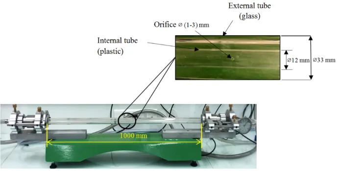
The different components of the experimental bench are illustrated on the schematic diagram of Figure 1. It consists of two concentric cylindrical tubes, one in plastic (PMMA) and the other in borosilicate glass. The inner plastic tube is perforated in order to create circular holes that enable the water in the tube to escape once pressurized. The escape of the pressurized water in the tube via the perforations leads to the formation of jets that impact the internal surface of the outer tube made of glass. Glass was chosen for its optical properties (transparency in the visible spectrum) and for its opacity to infrared radiation. This enables the visualization of the hollow space within the tube and permits the use of an infrared camera to measure the temperature of its external surface from which the heat exchange on the impinged surface can be characterized by an inverse method. The inner tube is connected to a thermostat (Lauda Proline RP845, No.6) with an in-built reservoir and pump. The thermostat thus has the double function of pumping the water and regulating its temperature. The flow rate of the water is regulated by varying the power of the pump and by adjusting the opening of the valve between the thermostat and the inner tube. This flow rate is measured accurately by an ultrasonic flow meter (Atrato 740-V10 D) installed between the thermostat and the inner tube’s inlet. The outer tube is connected to a
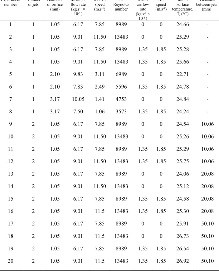
reservoir of compressed air regulated by a valve while the air pressure at the outlet of the air reservoir is measured by a pressure gauge (Bosch 1827231010). The flow rate of the air was measured by an airflow meter (SMC PFMB7501). An HD camera was used to visualize the different phenomena that took place within the tube during the impingement of the jets and their interaction with the air that flows perpendicularly to them in the annular space between both tubes. For the experiments involving heat transfer, the temperature of the outer surface of the glass tube was measured by means of an infrared camera (Optris PI640). The experiments conducted are summarized on Table 1.
An image of the experimental bench with the dimensions of the tubes is shown on Figure 2. Both tubes are 1000 mm long; the diameter of the inner tube is ∅12/10 mm while that of the outer tube is ∅33/30 mm. This leaves a distance of 9 mm (H) between the orifice and the internal surface of the outer tube. Different orifice diameters were tested and range from ∅ (1-3) mm. This gives orifice to surface distance and jet diameter ratios (H/dj) of 3, 4.5 and 9 respectively.
The experimental work was divided into 2 phases; a visualization of the fluid dynamics phase and a heat transfer phase. Different flow rates for both fluids were tested in order to study their effects on the jet and on the water film formed on the glass surface. For each experiment, water was allowed to flow in the inner tube for approximately 10 s in order to get rid of all the air trapped in the tubes. The valve at the exit of the tube was then closed in order to generate a higher pressure within the tube. This leads to the escape of the water from the orifices in the form of jets. During the experiments involving water and airflow, the valve regulating airflow is opened first and the airflow is allowed to stabilize for a few seconds before the release of the water jets. For the single jet experiments, the surface area occupied by the water film formed
during jet impingement for different flow parameters was measured from the images taken by the HD camera positioned above the tube.
Method
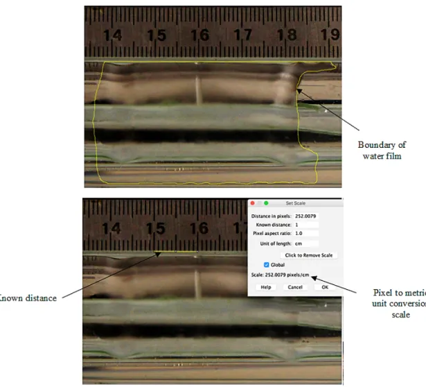
The area of the wetted area was measured by an open source image processing software known as ImageJ® by tracing contours along its boundaries. Before recording each experiment, a
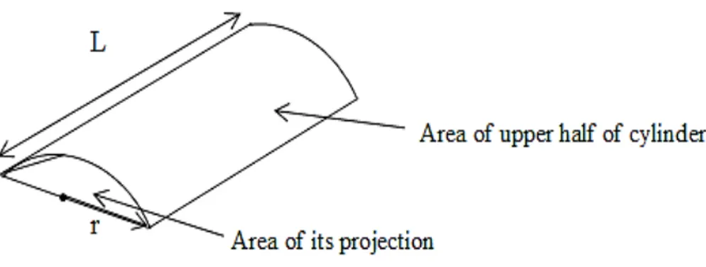
ruler was placed to the side of the tube in order to establish a scale that enabled the conversion of the pixels on the image to metric units as illustrated on Figure 3. Due to the fact that the tube is cylindrical and thus has a curved surface, the areas measured on the software are just a 2D projection of the real area. In order to take the effects of the surface’s curvature into account, the areas measured were multiplied by a factor obtained by taking the ratio of the area of the upper half of the cylinder to that of its projection as demonstrated by illustration of Figure 4. For each experiment, 20 measurements were made and the average value was taken.
Area of upper half of cylinder = πrL (1)
Area of its projection = 2rL (2)
Ratio of both areas = () (3)
The heat transfer phase of the experimentation involves heating the outer glass tube with hot water jets. The water is heated in the thermostat to the required temperature of 50 °C before being pumped to the perforated inner tube. During the impingement of the jets, the temperature of the external surface of the glass tube is measured by an infrared camera positioned directly above the surface of the tube along the jet’s axis.
Inverse heat conduction analysis
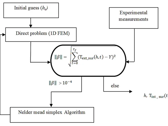
An inverse method was used to estimate the heat transfer coefficients and the heat flux at the jet stagnation area. The objective function which is the root mean square error between the
numerical computations and the experimental measurements was minimized iteratively by the Nelder-Mead simplex algorithm [13]. The temperature was measured from a circular area with a 1 mm diameter on the external surface whose centre lies on the same axis as the jet. The direct problem is modelled as a 1D heat conduction problem across the thickness of the glass tube (Figure 5) and is solved by the finite element method (FEM). A transient natural convective heat transfer coefficient is imposed on the external surface of the glass tube. This natural convective heat transfer coefficient is calculated from the correlating equation for a horizontal cylinder by Churchill and Chu [14] by using the external surface temperature measurements obtained. The jet heat transfer coefficient to be estimated is imposed on the internal surface of the glass tube. Using a 1D model is justified by the adiabatic conditions surrounding the jet stagnation area due to the uniform temperature distribution on the area occupied by the wetted area formed during jet impingement. Given that the jet stagnation area is small when compared to the wetted area (wetted area to stagnation area ratio of 600), heat conduction via the other axes is minimized. The heat flux is then calculated from the values of h and of the internal surface temperature vector (T int – sur (t)) obtained as well from the inversion analysis. The minimization procedure is
illustrated on the schematic diagram of Figure 6. * + , ,+-r. 𝑘 ,0 ,+ 1 = ρ𝑐4 ,0 ,5 , in Γ (4) q* = ℎ . [T:− T<=5 _ ?@+(𝑡)], on Γ1 (5) q) = ℎE (𝑡). [TFG5 _ ?@+− TE] , on Γ2 (6) Uncertainty analysis
The uncertainties on the different experimental parameters and calculations are presented. The uncertainties on the experimental measurements were obtained by dividing the values provided
by the manufacturers by √3 while the uncertainties on the calculated parameters were estimated by means of the propagation of uncertainty method. The approach used to determine the errors from the use of the inverse method is also described. The uncertainty on the airflow rate measurements were estimated by the manufacturers as 3% of the reading over the flow rate range of 5 - 500 l/min while the uncertainty on the water flow rate measurements were estimated as 1% of the reading over the flow rate range of 0.02 – 5 l/min. With regards to the temperature measurements, the uncertainty is the higher of ±2 °C or ±2% of the reading over the range -20 - 900 °C. Table 2 summarizes the uncertainties on the calculated parameters.
For the inverse method, the uncertainty on the estimated heat transfer coefficient with a confidence interval of 95% and 10 experimental samples was obtained from equation (7) [15].
∆ℎ = 1.812 × αMvar(ℎ) (7)
A value of 𝛼 = 0.316 which represents the noise of the temperature measurements was used while the variance of the heat transfer coefficient (var (h)) was calculated from equation (8).
var (h) = TSFG5_?@+ V S FG5_?@+W X* (8) where, SFG5_?@+ = ⎣ ⎢ ⎢ ⎡,0\]^_`ab,def,g ⋮ ,0\]^_`ab,di ,g ⎦ ⎥ ⎥ ⎤ (9)
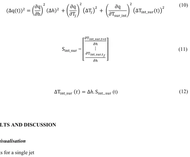
The uncertainty on the heat flux calculated was obtained by using the propagation of uncertainty method described by equation 10.
(∆q(t))) = n∂q ∂hq ) (∆ℎ)) + s∂q ∂T:t ) T∆T:W) + s ∂q ∂T?@+_<=5t ) T∆T<=5_?@+(t)W) (10) ∆T<=5_?@+ (𝑡) = ∆ℎ. S<=5_?@+ (t) (12)
RESULTS AND DISCUSSION
Flow visualisation
Results for a single jet
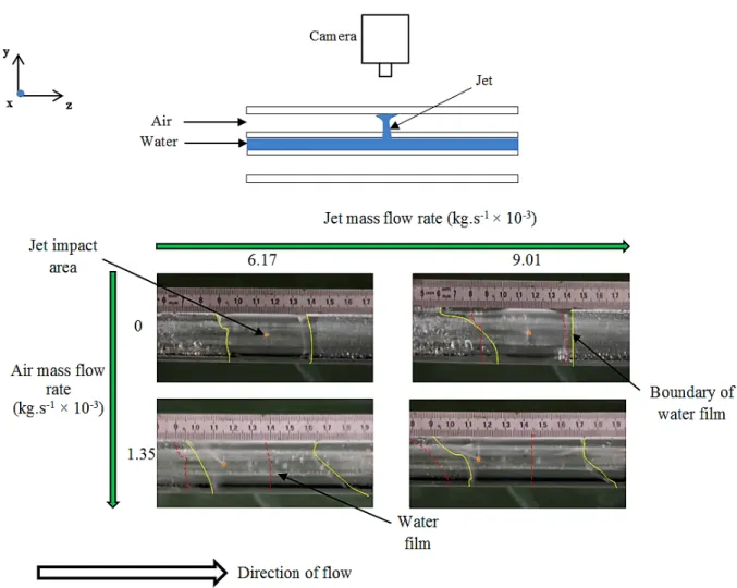
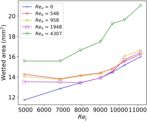
Figure 7 shows us the effects of varying the control parameters (jet and air mass flow rates) on the surface area of the water film that forms on the surface during the impingement of the jet (wetted area) are shown. The solid lines designate the boundaries of the water film at steady state while the broken lines designate the initial boundaries of the water film before a change in parameter. The areas of the water film measured for different fluid parameters by the methods described in the previous section are presented on Figure 8. It can be observed for a fixed orifice diameter that when there’s no airflow in the annular space between both tubes, the wetted area increases progressively until a critical value is attained above which there’s no further increase in the wetted area. This is due to the fact that most of the water splashes off the surface due to the relatively high jet velocity. Another observation that can be made is that airflow increases the wetted area for most jet Reynolds numbers (Rej) tested. The increase in the area by the airflow is
S<=5_?@+ = ⎣ ⎢ ⎢ ⎡,0uv^_`ab,def,g ⋮ ,0uv^_`ab,di ,g ⎦ ⎥ ⎥ ⎤ (11)
higher for lower jet Reynolds numbers (< 8000) when compared to the higher jet Reynolds numbers. However, for airflow Reynolds numbers (Rea) greater than 4000, there’s a significant
increase in the area of the water film for the entire range of jet Reynolds numbers tested.
Results for two adjacent jets
In addition to the studies performed on a single jet, the effects of the interactions between two adjacent jets were also studied. For a scenario with two adjacent water jets, an interference zone where the fluids originating from both jets meet is formed (Figure 9). This zone is characterized by a relatively lower heat flux when compared to the heat flux at the stagnation areas of both jets [10]. Increasing the flow rates of both jets also increases the area of the water film formed on the tube’s surface which can be observed by comparing the images of Figure 9 and Figure 10.
Effects of increasing the distance (s) between the jets are shown. Results presented are for a scenario with no airflow in the annular space. It can be observed that as the distance between the jets increases, a wider water film is formed and the interference zone between both jets gets wider.
Figure 11 shows us the effect of continually increasing the air mass flow rate for a given jet mass flow rate is shown. It’s observed that as the jet mass flow rate to air mass flow rate ratio increases, the jets deflect progressively until getting to a point where the air starts penetrating the internal tube via the orifices. This prevents the exit of the jets from the orifices. The mass flow rate ratio is obtained from the expression below:
𝜎 = 𝑚̇y 𝑚̇{
Influence of jet parameters on the temperature uniformity of the tube’s external surface
Results for a single jet
Different H/dj ratios were tested in order to study the effect of this parameter on the
temperature uniformity of the heated surface. As illustrated on Figure 12, the temperature was measured on the external surface of the glass tube along its length and along half its circumference at the jet impact area. Figure 13a and Figure 13b illustrate the temperature distribution on the external surface of the tube along the tube’s length and along its circumference for different jet diameters at times 10s, and 40s respectively is presented. The dimensionless temperature was obtained from the equation below:
T∗ = T − T} T:
(14)
The ambient temperature during the experiments ranged from (22-27) °C and was assumed to be equal to the initial temperature of the tube. It can be observed from Figure 13 that a H/dj ratio
of 4.5 has the widest uniformly heated area for the same jet mass flow rate of approximately 9.10-3 kg.s-1 when compared to the other ratios. We also notice that the airflow tends to shrink
the heated area before the jet stagnation point and expand the heated area after the jet stagnation point in the direction of the airflow. This phenomenon can be observed from the images of Figure 7. It’s safe to assume that increasing the airflow further will widen the heated area due to an increase in the wetted area as illustrated on the graph of Figure 8. Another observation is the fact that some of the temperature profiles have negative values. This could be due to the evaporation of water droplets that splash unto the parts of the tube that are not directly impacted by the jet. The reason for this hypothesis is the fact that the temperature drops below the ambient temperature and the negative temperature values are obtained only from the parts of the tube’s
surface that were attained by water droplets. The airflow in the tube could be responsible for the high evaporation rates.
With regards do the temperature distribution along the upper half of the tube’s circumference, a rather uniform temperature distribution is observed and the airflow doesn’t affect the temperature distribution. The temperature measurement was limited to the range (-60° - +60°) with the jet axis being the line of reference for the angle measurements. This limitation is due to the effect of the directional dependency of the tube surface emissivity as demonstrated in the study of Ibos et al. [16]. This therefore makes the measurements obtained from angles beyond 60° or -60° unreliable.
Results for two adjacent jets
In a similar manner to what was done during the tests performed on a single jet, the temperature distribution on the external surface of the heated tube was measured for a scenario involving the simultaneous impact of the tube’s internal surface by two adjacent jets. This study was performed in order to identify the ideal spacing between the jets (dj = 1 mm) for a uniform
temperature distribution along the impacted surface. The positioning of the jets is illustrated on Figure 14. Figure 15a and Figure 15b show us the temperature distribution on the external surface of the glass tube for different times during the impingement of the tube for a single jet Reynolds number of 8989. It’s assumed that the total flow rate of the water is equally divided among the jets leading to identical Reynolds numbers. The reason for this assumption is the fact that the orifices are almost identical and the pressure of the water is uniformly distributed along the tube. It can be observed from the graphs that as the distance between the jets increases, a wider area is heated and the airflow tends to have the same effect observed in the previous study where the heated area before the first jet’s stagnation area is reduced and that after the second jet’s stagnation area in the direction of the airflow increases.
Influence of the Reynolds numbers of both fluids on the heat transfer at the jet stagnation area
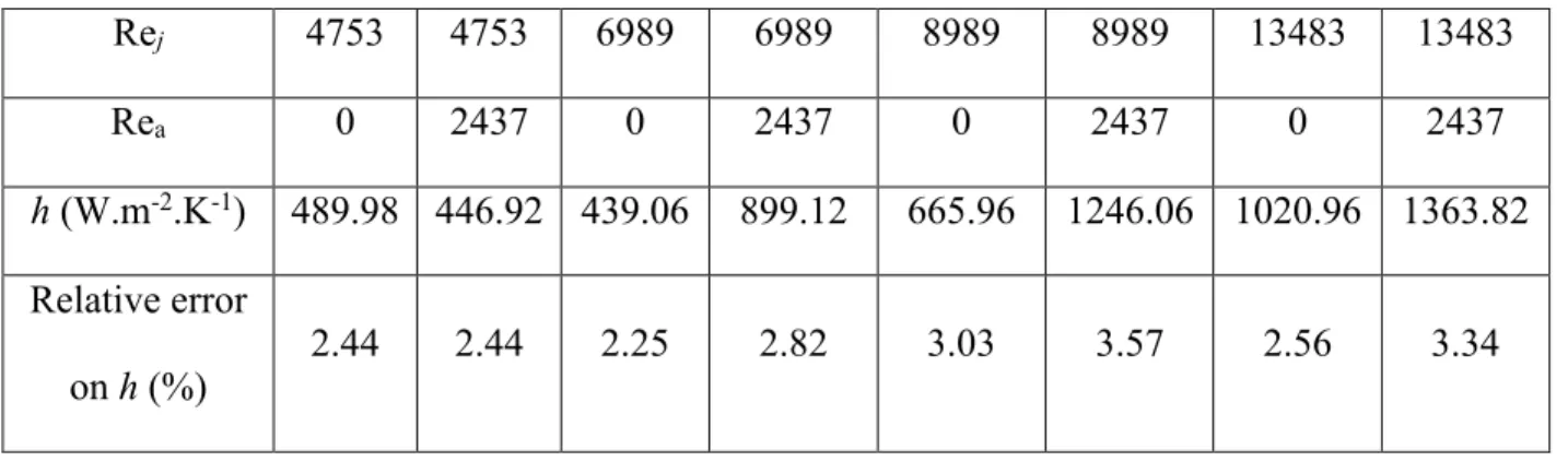
The effect of different Reynolds numbers of both the jet and the airflow on the stagnation area heat transfer between the jet and the surface is studied. Figure 16 illustrates the zone where the temperature is measured on the external surface of the glass tube while Figure 17 shows the experimental measurements made. The heat transfer coefficients estimated are presented on Table 3 while the heat fluxes estimated (Figure 18a) are placed by the side of their estimated relative errors (Figure 18b). After analyses, it was observed that the differences between the temperature profiles obtained from the 3 highest Reynolds numbers are lower for the scenario with a cross airflow. However, for the lowest jet Reynolds number of 4753, the gap is widened. This can be explained by the enhancement in the jet stagnation area heat transfer coefficient by the airflow for some combinations of jet Reynolds numbers to air Reynolds numbers. This enhancement was found to depend on the ratio of the Reynolds numbers of both fluids as illustrated on Figure 19. The enhancement in the heat transfer coefficient peaks at a ratio of 2.87 and tends to decrease progressively as the ratio increases. However, reducing the jet’s Reynolds number to air Reynolds number ratio below 2.87 has a negative effect on the heat transfer coefficient which reduces from its original value obtained without airflow. The errors on the heat transfer coefficient were taken into account in the calculation of its percentage enhancement as described in equation (15).
Enhancement in ℎ = ( g„…†i‡ˆ‰
The hypothesis proposed to explain this enhancement is the turbulence generated at the jet stagnation area due to the interaction between both fluids. The variations in the enhancement could be explained by the variations in the turbulence intensity which could depend on the ratio of the Reynolds numbers of both fluids. However, when the ratio is relatively low (< 2.87) the airflow tends to have a negative effect on jet heat transfer performance.
CONCLUSIONS
The influence of airflow on the hydrodynamics of an impinging jet and the water film formed on the surface after impact was visualized and its area measured for a single jet. The interaction between two adjacent jets with different separation distances between them was also visualized. The influence of the air/jet and jet/jet interactions on the heat transfer with no phase change between the jet and the surface was also studied. These studies revealed that:
1. Imposing airflow in the area between an impinging jet and the impacted surface spreads out the water film that forms on the surface thereby increasing its area for certain jet to air Reynolds numbers ratios. For the flow parameters tested, the wetted area could be increased by as much as 40 % by the airflow. This means that when cooling or heating a certain area by water jets, introducing a cross airflow could reduce the number of jets needed for a homogeneous cooling/heating of the surface. For values of σ < 0.75, the water jets start tilting under the force of the airflow until getting to a point where the jets are unable to exit the orifices.
2. The heat transfer coefficient at the jet stagnation area can be enhanced by as much as 114% and depends on the jet to air Reynolds number ratio. This could be brought about by
variations in the turbulence intensity which could be linked to the interaction between both fluids.
3. For a single jet, the optimum performance in terms of the size of the area that is heated uniformly was obtained with a H/dj ratio of 4.5. For two jets, uniform heating/cooling could
still be achieved by increasing the s/dj ratio to 50.
ACKNOWLEDGEMENTS
: The authors would like to thank Pierre Mousseau and AlainSarda for their guidance during the experimental phase of this research and they are also grateful to Yannick Madeck and Erwann Paviot for their help during the assembly of the experimental bench.
NOMENCLATURE
cp specific heat, J.kg-1.K-1
D canal diameter, m
dj jet orifice diameter, m dtube external diameter of tube, m
e thickness of glass tube, m
FEM Finite element method
g gravity, m.s-2
H distance between jet orifice and tube’s internal surface, m h heat transfer coefficient, W.m.-2K-1
L tube length, m 𝑚̇ mass flow rate, kg.s-1
PMMA poly(methyl methacrylate)
q heat flux, W.m-2
r radius of canal section, m
Re Reynolds number
Rea Reynolds number of airflow, •„(•X‘• d’“”)
„
Rej Reynolds number of jet, ••–‘–
‰
s jet separation distance, m
S sensitivity vector
T temperature, °C
t time, s
V velocity, m.s-1
x, y, z coordinate axes
Y experimental temperature measurements, °C
Greek symbols 𝜃 angle, degrees ρ density, kg.m-3 Γ domain Ø Diameter, m v kinematic viscosity, m2.s-1
α measurement noise, °C
β objective function
Subscripts
a air
ext_sur external surface
f final
i initial
int_sur internal surface
j jet o initial guess t total w water ∞ ambient Superscript * dimensionless REFERENCES
[1] S. Marques, A. F. de Souza, J. Miranda, and I. Yadroitsau, "Design of conformal cooling for plastic injection moulding by heat transfer simulation", Polimeros, vol. 25, no. 6, pp. 564–574, 2015. DOI: https://doi.org/10.1590/0104-1428.2047.
[2] G. Tymen et al., "Temperature mapping in a two-phase water-steam horizontal flow",
Experimental Heat Transfer, vol. 31, no. 4, pp. 317–333, 2018.
[3] M. Bouhadef, "Étalement en couche mince d’un jet liquide cylindrique vertical sur un plan horizontal", Zeitschrift für angewandte Mathematik und Physik ZAMP, vol. 29, no. 1, pp. 157–167, Jan. 1978. DOI: 10.1007/BF01797312.
[4] E. J. Watson, "The radial spread of a liquid jet over a horizontal plane", Journal of Fluid Mechanics, vol. 20, no. 3, pp. 481–499, Nov. 1964. DOI: 10.1017/S0022112064001367. [5] X. S. Wang, Z. Dagan, and L. M. Jiji, "Heat transfer between a circular free impinging jet
and a solid surface with non-uniform wall temperature or wall heat flux—1. Solution for the stagnation region", International Journal of Heat and Mass Transfer, vol. 32, no. 7, pp. 1351–1360, 1989. DOI: https://doi.org/10.1016/0017-9310(89)90034-3.
[6] B. Elison and B. W. Webb, "Local heat transfer to impinging liquid jets in the initially laminar, transitional, and turbulent regimes", International Journal of Heat and Mass Transfer, vol. 37, no. 8, pp. 1207–1216, 1994. DOI: https://doi.org/10.1016/0017-9310(94)90206-2.
[7] X. Liu, V. Lienhard J. H., and J. S. Lombara, "Convective Heat Transfer by Impingement of Circular Liquid Jets", J. Heat Transfer, vol. 113, no. 3, pp. 571–582, Aug. 1991. DOI: 10.1115/1.2910604.
[8] X. Liu and J. Lienhard, "Liquid Jet Impingement Heat Transfer on a Uniform Flux Surface", Heat Transfer Phenomena in Radiation, Combustion, and Fires, ASME HTD, vol. 106, no. 498, pp. 523-530, 1989. (26th ASME/AIChE National Heat Transfer
Conference, Philadelphia, Aug. 6-9, 1989).
[9] G. Hu and L. Zhang, "Experimental and Numerical Study on Heat Transfer with Impinging Circular Jet on a Convex Hemispherical Surface", Heat Transfer Engineering, vol. 28, no. 12, pp. 1008–1016, 2007. DOI: 10.1080/01457630701483638.
[10] M. A. Teamah and M. M. Khairat, "Heat transfer due to impinging double free circular
jets", Alexandria Engineering Journal, vol. 54, no. 3, pp. 281–293, 2015. DOI: https://doi.org/10.1016/j.aej.2015.05.010.
[11] S. Ishigai, S. Nakanishi, M. Mizuno, and T. Imamura, "Heat Transfer of the Impinging Round Water Jet in the Interference Zone of Film Flow along the Wall", Bulletin of JSME, vol. 20, no. 139, pp. 85–92, 1977. DOI: 10.1299/jsme1958.20.85.
[12] L. M. Al-Hadhrami, "Study of Heat Transfer Distribution in a Channel with Inclined Target Surface Cooled by a Single Array of Staggered Impinging Jets", Heat Transfer Engineering, vol. 31, no. 3, pp. 234–242, 2010. DOI: 10.1080/01457630903304665.
[13] J. Lagarias, J. Reeds, M. Wright, and P. Wright, "Convergence Properties of the Nelder--Mead Simplex Method in Low Dimensions", SIAM J. Optim., vol. 9, no. 1, pp. 112–147, Jan. 1998. DOI: 10.1137/S1052623496303470.
[14] S. W. Churchill and H. H. S. Chu, "Correlating equations for laminar and turbulent free convection from a horizontal cylinder", International Journal of Heat and Mass Transfer, vol. 18, no. 9, pp. 1049–1053, 1975. DOI: https://doi.org/10.1016/0017-9310(75)90222-7. [15] M. N. Ozisik,. H. R. B. Orlande, and A. J. Kassab, "Inverse Heat Transfer: Fundamentals
and Applications", Applied Mechanics Reviews, vol. 55, no. 1, pp. B18–B19, Jan. 2002. DOI: 10.1115/1.1445337.
[16] L. Ibos, J. P. Monchau, V. Feuillet, and J. Dumoulin, "Investigation of the directional emissivity of materials using infrared thermography coupled with a periodic excitation", presented at the 13th Quantitative Infrared Thermography Conference, Gdansk, Poland, Jul. 2016.
Table 1: Summary of different parameter values for the experiments on heat transfer
Table 2: Uncertainties on experimental and calculated parameters
Experiment
number Number of jets Diameter of orifice (mm) Mean jet flow rate (kg.s-1 × 10⁻³ ) Jet exit speed (m.s-1) Jet Reynolds number Mean airflow rate (kg.s-1 × 10⁻³ ) Air speed (m.s-1) Initial surface temperature, Ti (°C) Distance between jets (mm) 1 1 1.05 6.17 7.85 8989 0 0 24.66 - 2 1 1.05 9.01 11.50 13483 0 0 25.29 - 3 1 1.05 6.17 7.85 8989 1.35 1.85 25.28 - 4 1 1.05 9.01 11.50 13483 1.35 1.85 25.66 - 5 1 2.10 9.83 3.11 6989 0 0 22.71 - 6 1 2.10 7.83 2.49 5596 1.35 1.85 24.78 - 7 1 3.17 10.05 1.41 4753 0 0 24.84 - 8 1 3.17 7.50 1.06 3573 1.35 1.85 24.24 - 9 2 1.05 6.17 7.85 8989 0 0 24.54 10.06 10 2 1.05 9.01 11.50 13483 0 0 25.26 10.06 11 2 1.05 6.17 7.85 8989 1.35 1.85 25.29 10.06 12 2 1.05 9.01 11.50 13483 1.35 1.85 25.75 10.06 13 2 1.05 6.17 7.85 8989 0 0 24.06 20.08 14 2 1.05 9.01 11.50 13483 0 0 25.12 20.08 15 2 1.05 6.17 7.85 8989 1.35 1.85 24.58 20.08 16 2 1.05 9.01 11.5 13483 1.35 1.85 25.30 20.08 17 2 1.05 6.17 7.85 8989 0 0 25.91 50.10 18 2 1.05 9.01 11.5 13483 0 0 26.73 50.10 19 2 1.05 6.17 7.85 8989 1.35 1.85 26.54 50.10 20 2 1.05 9.01 11.5 13483 1.35 1.85 26.92 50.10
Experimental parameter Uncertainty
Temperature of the water ± 1 ℃
Tube’s surface temperature ± 1.1 ℃
Jet flow rate ± 1%
Air flow rate ± 3 %
Jet exit speed ± 9.8 %
Air speed ± 1.7 %
Wetted area ± 5 %
Reynolds number of jet ± 11 %
Table 3: Estimated heat transfer coefficients at the jet stagnation area for different flow parameters Rej 4753 4753 6989 6989 8989 8989 13483 13483 Rea 0 2437 0 2437 0 2437 0 2437 h (W.m-2.K-1) 489.98 446.92 439.06 899.12 665.96 1246.06 1020.96 1363.82 Relative error on h (%) 2.44 2.44 2.25 2.82 3.03 3.57 2.56 3.34
List of figures
Figure 1: Schematic illustration of the experimental bench and of its different components Figure 2: Image of the experimental bench with dimensions of the concentric tubes
Figure 3: Measurement of area of water film by an image processing software Figure 4: Illustration of approach used to obtain the real wetted area
Figure 5: 1D model of direct problem
Figure 6: Schematic illustration of the inverse method
Figure 7: Influence of fluid flow rates on the hydrodynamics of the film (Top view) Figure 8: Effect of the Reynolds numbers of both fluids on the wetted area
Figure 9: Visualization of water film and of interference zone formed between two adjacent jets dj =1 mm, 𝑚̇5 = 11.33. 10X› kg/s , s/dj = 20, a) Side view, b) Top view
Figure 10: Visualization of water film and of interference zone formed between two adjacent jets
for different separation distances (dj =1 mm), a) 𝑚̇5= 13.67. 10X› kg/s , s/dj = 10,
b) 𝑚̇5 = 16.67. 10X› kg/s , s/dj = 20, c) 𝑚̇
5= 15.33. 10X› kg/s , s/dj = 50
Figure 11: Effect of continually decreasing the air mass flow rate (dj =1 mm), a) 𝜎 =0.75
b) 𝜎 = 0.61 , c) 𝜎 = 0.52
Figure 12: Illustration of the positions of the different temperature profiles measured
Figure 13: Temperature distribution along the tube’s length L (left) and tube’s half circumference θ (right) for a) t = 10 s, b) t = 40 s
Figure 14: Illustration of jet placement and position of infrared camera
Figure 15: Temperature distribution along the tube’s length for Rej = 8989, a) t= 10 s, b) t= 30 s
Figure 16: Illustration of the measurement point of the temperature with respect to time
Figure 17: Evolution of the temperature on the area of the tube’s external surface that’s directly above the jet stagnation area for different combinations of jet and air Reynolds numbers
Figure 18: Heat flux at jet stagnation area: a) Evolution of the heat flux with respect to time, b) Relative uncertainty on the heat flux values
Figure 19: Influence of the Reynolds numbers ratio on the heat transfer coefficient at jet stagnation area
1- HD/infrared Camera, 2- compressed air reservoir, 3- air valve, 4- Manometer, 5- airflow meter, 6- water reservoir, 7- water valve at tube inlet, 8- water flow meter, 9- airflow, 10- water
jet, 11- PMMA tube, 12- glass tube , 13- air/water mixture exit, 14- water valve at tube outlet Figure 1: Schematic illustration of the experimental bench and of its different components
Figure 9: Visualization of water film and of interference zone formed between two adjacent jets dj =1 mm, 𝑚̇5 = 11.33. 10X› kg/s , s/dj = 20, a) Side view, b) Top view
Figure 10: Visualization of water film and of interference zone formed between two adjacent
jets for different separation distances (dj =1 mm), a) ṁ5 = 13.67. 10X› kg/s , s/dj = 10,
Figure 11: Effect of continually decreasing the air mass flow rate (dj =1 mm), a) 𝜎 =0.75
a)
b)
Figure 13: Temperature distribution along the tube’s length L (left) and tube’s half circumference θ (right) for a) t = 10 s, b) t = 40 s
a)
b)
Figure 15: Temperature distribution along the tube’s length for Rej = 8989, a) t= 10 s, b) t= 30 s
Figure 17: Evolution of the temperature on the area of the tube’s external surface that’s directly above the jet stagnation area for different combinations of jet and air Reynolds numbers
a)
b)
Figure 18: Heat flux at jet stagnation area: a) Evolution of the heat flux with respect to time, b) Relative uncertainty on the heat flux values
Figure 19: Influence of the Reynolds numbers ratio on the heat transfer coefficient at jet stagnation area
Notes on contributors
Emmanuel Kwadwo Kale Agyeman is a Doctoral student at the University of Nantes, France. He obtained his BSc. in Mechanical Engineering from the Kwame Nkrumah University of Science and Technology, Ghana and later on pursued an MSc. in Applied Mechanical Sciences (Option: Thermal energy and sciences) at Polytech Nantes (University of Nantes). His research interests are in multiphase cooling, convective heat transfer, automatic control and inverse heat conduction.
Denis Edelin is an associate professor at the mechanical engineering school of Icam Ouest, France. He received his doctoral degree from the food industry school Oniris after studying ice slurry technology. His current research, done at the University of Nantes, is about innovative technology based on phase change materials, enabling the controlled cooling of industrial processes with precision and homogeneity.
Damien Lecointe is a Thermal engineer who graduated in 1995 from “Ecole Polytechnique de l’Université de Nantes” and later pursued a PhD in thermal characterization for the Resin Transfer Molding composites manufacturing process. He continued to work on RTM process simulations in AIRBUS group research center at Suresnes. He moved to Toulouse in 2001 and joined the ALTRAN group and worked on thermal certification of structures and systems of Airbus A380 and A350 programs. In 2011, he joined Epsilon Ingenierie company as a team leader and developed new activities based on multi-physical dynamic system simulations in different industrial sectors: space, building, nuclear and hydrogen. He joined IRT Jules Verne in 2018 and has been involved in different projects as a simulation expert. His main skills are in heat transfer, fluid flow, energy, numerical modeling and simulation of dynamic systems.