CONSTITUTIVE EQUATIONS FOR HOT WORKING OF ALUMINUM ALLOY 6061
by
Wende Sue2ates
SUBMITTED TO THE DEPARTMENT OF MECHANICAL ENGINEERING IN PARTIAL FULFILLMENT OF THE REQUIREMENTS
FOR THE DEGREE OF BACHELOR OF SCIENCE
at the
MASSACHUSETTS INSTITUTE OF TECHNOLOGY
June 1986
@Massachusetts
Institute of Technology 198647
f\/(Signature of Author
Department of Mechanical Engineering May 16, 1986 Certified by
'K),
Accepted byProfessor Lallit Anand Thesis Supervisor
Peter Griffith Chairman, Departmental Committee
JUN
1
9
19
CONSTITUTIVE EQUATIONS FOR HOT WORKING OF ALUMINUM ALLOY 6061
by
Wende Sue Gates
Submitted to the Department of Mechanical Engineering on May 16, 1986 in partial fulfillment of the requirements
for the Bachelor of Science Degree.
ABSTRACT
Large deformation, constant true strain rate, isothermal compression tests have been conducted on aluminum alloy 6061 at strain rates ranging from 10-3 to 1 sec- 1, and temperatures spanning the range of 350"C to 5000C. For this range of strain rates and temperatures, the material exhibits very little strain hardening, and the relationship between the plastic strain rate, iP, the temperature, T, and the flow stress, a, can be represented by the classical constitutive equation:
kTp1 e = (gn(a)_e)
with A=3.13 x 10⁹sec- 1, Q=2.18 x 10⁻¹⁹J, m=0.15, and where a0=40 MPa is a
reference stress, k is Boltzmann's constant and agn (1) is the signum function. This constitutive equation should be of wide utility in analyzing slow-rate hot deformation processing of this alloy.
Contents
1 INTRODUCTION 2 EXPERIMENTAL PROCEDURE 2.1 Experimental Facility ... 2.2 Experimental Procedure ... 3 EXPERIMENTAL RESULTS 4 CONSTITUTIVE EQUATION 5 CONCLUSIONS 6 ACKNOWLEDGEMENTS 7 REFERENCES 8 FIGURES 9 APPENDIX 11 261
INTRODUCTION
Aluminum alloy 6061 is one in a class of Aluminum-Magnesium-Silicon alloys in which the magnesium and silicon combine to precipitate as Mg2Si in the heat treated or
aged condition. The first of the 6XXX series alloys was introduced in 1920. Alloy
6061, although developed in the early 1930s, has remained one of the most important
intermediate strength, general purpose aluminum alloys in the industry. The actual composition of this alloy is: 97.95% aluminum, 1.0% magnesium, 0.60% silicon, 0.25% copper and 0.20% chromium by weight[l]. Recently, the increased use of this alloy in die forgings has enabled the manufacture of lighter, more fuel efficient automobiles.
General Motors is utilizing an increased number of forgings make from A16061 in their new design for the Corvette. With 6061 forgings, they have produced an automobile with over 400 lbs in aluminum parts, including the rear wheel suspension system. This has resulted in a 200 lb reduction in the weight of the new Corvette, which translates into a 7% increase in acceleration and a reduction in fuel consumption of 0.5 mile per gallon. Increased efficiency and cost reductions have been noted throughout the manufacturing process, because use of aluminum forgings reduces material waste and the need for further machining. In addition, the complex precision forgings provide easier part assembly primarily by reducing the number of parts to be assembled[2].
For centuries, the forging process has been based upon trial-and-error for part and die design. Because the process depends on stress, strain, temperature, strain rate,
friction and material properties, forging models have been unwieldy. However, the recent maturing of large deformation finite element programs, and the availiability of super computers is making the complexity of analyzing the forging process more tractable. Computer simulation provides the engineer with a means of assessing the feasibility of a product, estimating die loads and predicting material flow patterns, all without the actual cost of materials, die manufacture or labor[3].
An essential input to these finite element programs is an appropriate constitutive equation for the flow stress as a function of strain, strain rate and temperature. Such equations are obtained through isothermal, constrant true strain rate compression tests[4]. This paper presents the results of hot- compression testing and a constitutive equation for the hot working of aluminum alloy 6061.
2
EXPERIMENTAL PROCEDURE
2.1
Experimental Facility
Figure 1 shows a picture of the experimental facility. The hot-compression testing facility is built around an Instron Model 2150 servo-hydraulic machine equipped with a 5000 kgf load cell. A decaying exponential command signal to the actuator is required for a constant true strain rate compression test. A function generator based on a discharging capacitor circuit is utilized, in which, both the decay step, and the decay rate may be selected through different potentiometer settings. In these tests, strains to approximately -95% are desired. Since the initial specimen height is 19.05
generator is set to produce a voltage output, or stroke command, which decays from
0 to -12 volts. A trigger is set to hold the signal at -11.7 volts. The decay rate,
which determines the constant true strain rate, can be changed by altering circuit resistances. With these circuit parameters verified, the function generator may be manually triggered to discharge the pre-charged circuit capacitor.
In order to maintain a constant temperature environment, a Model E4 Quad Ellip-tical Radiant Heating Chamber is mounted within the Instron frame. Manufactured
by Research Incorporated, this furnace provides uniform radiant energy to the test
specimen through four high-temperature, tungsten filament quartz lamps. An ellip-tical reflector focuses the radiant energy onto the specimen. Power is supplied to the filaments by a Centorr variable power source, which is controlled by an Omega digital temperature controller. A chromel-alumel thermocouple inserted into the test specimen measures the specimen temperature.
Output voltage signals for the load and stroke are indicated on the Instron digital readout and on a voltmeter. However, for recording test data, an HP 6035B X-Y Plotter and an IBM Personal Computer with the Unkelscope@ data acquisition system are used.
With this experimental facility, isothermal, constant true strain rate compression tests on cylindrical specimens of 6061 were performed by following the procedure outlined below.
2.2
Experimental Procedure
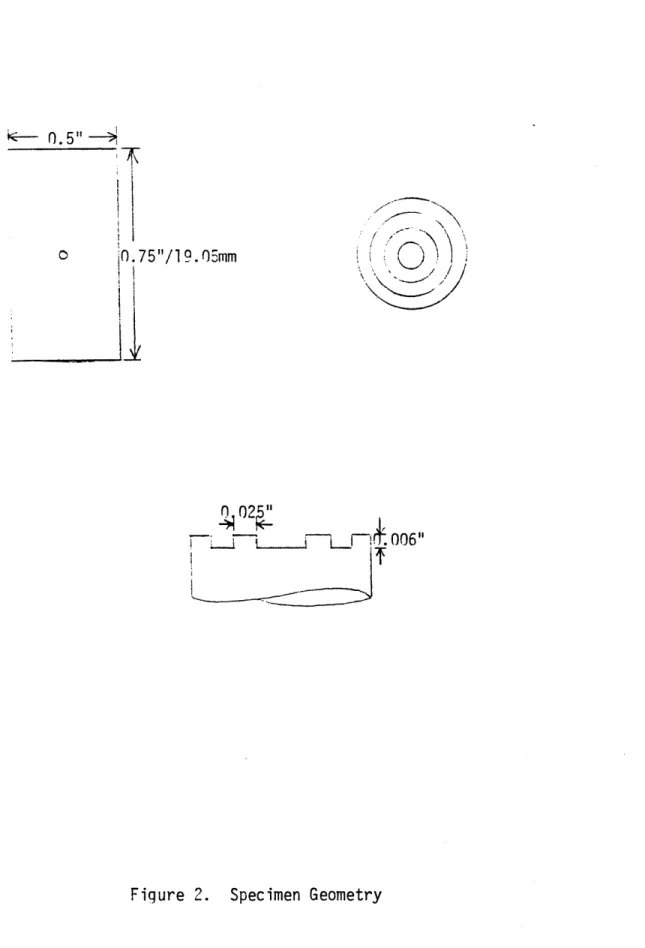
Test specimens were prepared from 0.5 inch diameter aluminum 6061 extruded rod. They were machined to the dimensions specified in Figure 2. The height to diameter ratio of the specimens was 1.5. End grooves are necessary for holding lubricant, which in turn, promotes homogeneous deformations without barrelling. In order to initialize the microstructure of the specimens before testing, the aluminum cylinders were heated at 4150C for 2 hours, or annealed to the O temper.
Next, proper lubricants were selected to insure homogeneous deformations within the sample and to inhibit fusion of the specimen to the platens at high temperatures. At 3500C, D-Agent 41, an alephatic hydrocarbon manufactured by Acheson Colloids, was found successful. At higher temperatures, Corning Glass Powders were useful: a
1:1 volume ratio of powder 8463 and powder 7570 at 4500C, and powder 7570 alone
at 5000C.
Lubricants were placed upon the astroloy platens and the specimen ends in a thin layer and allowed to air dry. Then, the sample was centered between the platens, and finally, between the alumina rods as shown in Figure 1. The ceramic rods made of AlsOs were utilized to promote temperature uniformity within the specimens. In
addition, a cooling water system was employed to cool the astroloy rods and the outside walls of the radiant heating furnace.
Correct placement of the specimen within the test rods was important, as unbal-anced loads produced not only non-uniform deformations, but also the possibility of
damage to the radiant heating lamps. To reduce this risk, a glass cylinder was placed around the specimen, platen and ceramic rod assembly to contain any ejected objects. With the thermocouple inserted in the specimen and connected to the tempera-ture controller, the cooling system was started, the set point temperatempera-ture was selected and the power supply was activated. While the specimen was heating, the function generator signal was verified, and the x-y plotter and computer code were calibrated and manually tested. When equilibrium was reached inside the furnace, the Instron actuator, the x-y plotter and the computer were activated and the decay signal trig-gered.
During the compression tests, which ranged from one second to 15 minutes, load and stroke values were monitored on the plotter and the computer console. When completed, all systems were shut down and the sample removed and water quenched. While the facility was cooling down, binary data was stored onto a floppy disk.
Tests were valid only if uniform deformations were obtained. Samples exhibiting gross barrelling or shearing signaled invalid tests which were repeated.
In all, a 3 x 4 test matrix was successfully completed, at temperatures of 350C, 4500C and 500*C, and strain rates of 100, 10-1, 10- 2 and 10- S. In order to gener-ate true stress-true strain curves and statistically analyze the data, the binary load versus stroke data was translated to ACSII code and sent to a Data General super-minicomputer system via a modem.
3
EXPERIMENTAL RESULTS
The load versus displacement data collected during compression testing was converted to true stress-true strain data through a computer code, TRUECON. A listing of this FORTRAN program is provided in the Appendix. After requesting initial geometries, conversion factors and thermal properties, the program generated stress and strain values, by taking into account changes in specimen cross-sectional area and thermal expansion at initial heating.
Next, this converted data was initialized and smoothed by a second FORTRAN code, POLYS1, which can also be found in the Appendix. Finally, the experimental data was plotted utilizing a plotting routine, SBPLOT. The results of the compres-sion tests are displayed in Figures 3 through 9.
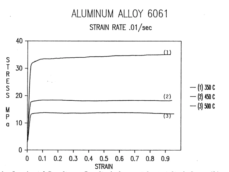
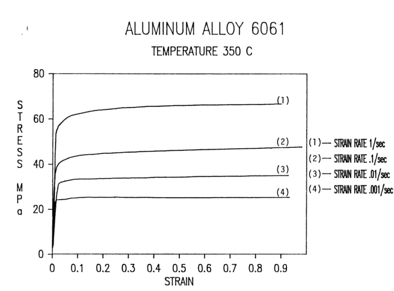
These figures show essentially constant values of stress over the strain range, 0.1 to 0.9, indicating that aluminum alloy 6061 does not strain harden in the range of temperatures and strain rates studied. Also as expected, at a constant temperature the flow stress increases with strain rate, and at a constant strain rate it decreases with increasing temperature.
4
CONSTITUTIVE EQUATION
In the practically important range of temperatures 3500C to 50000C the flow stress
of A16061 was found to be independent of strain for strain rates spanning the range
classical constitutive equation proved to be adequate to model the temperature and strain rate sensitivity of the flow stress:
?=-- Aexp agn() (1)
Here,
P ....Plastic strain rate (sec- 1)
T....Absolute temperature (oK) o....Flow stress (MPa)
A....Pre-exponential factor (sec 1) Q....Activation energy (J)
m....Strain rate sensitivity (dimensionless) k....Boltzmann's constant (1.381 x 10⁻²SJ/OK)
ao ....Representative stress level (40MPa)
sgn (1)....Signum function.
The computer code which was utilized to fit the data to equation (1) was entitled
CONSTS, may also be found in the Appendix. The material constants generated
from this exercise are A=3.13 x 10⁹see- 1, Q=2.18 x 10-"J and m=0.15. If the
tem-perature dependence of the flow stress is expressed as exp (- ) instead of exp
-where R is the universal gas constant, then Q*=131.5 kJ/mole. This value compares with a value of 142 kJ/mole for the activation energy for lattice self-diffusion in alu-minum[5].
With these values of the material parameters and the strain rates and temperatures in the test matrix, values of the flow stress were calculated using equation (1). These values are compared with the measured ones in Figures 10 to 13. The agreement is good.
5
CONCLUSIONS
In summary, the results of isothermal, constant strain rate compression tests are con-clusive and consistent. Strain hardening is not exhibited in the temperature and strain rate range studied here, and this allows for the formulation of the simple constitutive equation described above. This constitutive equation requires three material parame-ters, which can be determined through a non-linear least-squares routine. The values obtained for A, Q and m are within the expected ranges and magnitudes, and they provide flow stress predictions in good agreement with experimental values.
Finally, to verify the utility of the constitutive equation developed here, it should be used in a finite element program, such as ABAQUS, to simulate a forging process and the results compared to an actual aluminum 6061 forging.
6
ACKNOWLEDGEMENTS
Support for this experimental work was provided by NSF Grant No: MEA-8315117 under the supervision of Professor Lallit Anand. The author is grateful to Profes-sor Anand, Kwon Hee Kim, Shoichi Hashimoto, Stuart Brown, Mehrdad Haghi and
7
REFERENCES
[1] Hatch, J. E., ed., Aluminum - Properties and Physical Metallurgy, American Society for Metals, Metals Park, Ohio, 1984.
[2] Aluminum Forging: The Competitive Edge, videocassette from Aluminum Association, 1984.
[3] Rebelo, N., "Finite Elements for Better Forgings",
Machine Design, vol. 58, no. 3, February 6, 1986.
[4] Oh, S.I., Kobayashi, P., and Altan, T., "Application of FEM Modeling to Simulate Metal Flow in Forging a Titanium Alloy Engine Dish", Journal of Engineering for Industry, vol. 105, no. 4, November 1983.
[5] Frost, H.T. and Ashby, M. F., Deformation-Mechanism-Maps:
8
FIGURES
1 1
Astroloy loadinq rod
istrolov nlaten Copper c Alumina A1 6061 ooling collar rod Specimen Experimental Facility I i R L Figure 1.
---
.5"--I
0 0O75"/19.05mm },
02:
-_F-. 006"
ALUMINUM ALLOY 6061
STRAIN RATE
.001/sec
40
-I30
-20
-
10--I0
0.1
0.2 0.3 0.4 0.5 0.6 0.7 0.8 0.9
STRAIN
Experimental True Stress-True Strain Curves for Constant Strain Rate,
(1)
(2) (3) - (1)- (2)
-(3)
Figure 3. .001/sec.0 0 0
ALUMINUM ALLOY 6061
STRAIN RATE
.01/sec
- (1)
350
C
- (2)
450
C
- (3)
500 C
0
0.1
0.2 0.3 0.4 0.5 0.6 0.7 0.8 0.9
STRAIN
True Stress- True Strain Curves at Constant Strain Rate,
40
30
20
10
0 0 0 0 0 0 9
ALUMINUM ALLOY
STRAIN RATE OF 0.
6061
1/s
(1) (2) (3)0
0.1
0.2 0.3 0.4 0.5 0.6 0.7 0.8 0.9
STRAIN
- (1)-(2)
-(3)
True Stress-True Strain Curves at Constant Strain Rate,
60
45
30
15
350 C
450 C
500 C
.1/sec. Figure 5. ExperimentalALUMINUM ALLOY 6061
STRAIN RATE OF 1/sec
80
60
40
20
0
-(1)
350
-
(2)450
-(3)
500
0
0.1
0.2 0.3 0.4 0.5 0.6 0.7 0.8 0.9
STRAIN
Experimental True Stress-True Strain Curves at Constant Strain Rate, I/sec.
0 9 0 0 0 0 0 0 00 S
0 0 I I I I I I
0.1
0.2 0.3 0.4 0.5 0.6
STRAIN
I 0.8 0.90.7 0.8 0.9
(I) - SRMN RAE I/50
(2)-
SIRAIN
RATE
.1/sec
(3)-
STRAIN RAE.01/sec
(4)-
STRAIN
RATE.001/sec
Figure 7. Experimental True Stress-True Strain Curves at Constant Temperature, 3500 C.
80
60
-40
-20
-ALUMINUM ALLOY 6061
TEMPERATURE 350 C
0
0
0
(1)
(2)
(3)
(4)
0 0 0
ALUMINUM ALLOY 6061
TEMPERATURE 450 C
-I I I I I I I I I I0
0.1
0.2 0.3 0.4 0.5 0.6 0.7 0.8 0.9
STRAIN
0 0 0 0(1)
- STRAIN RAIE I/se
(2)-
SIJN
RAE
.1/sec
(3)-
SAIN RATE
.01/sec
(4)
- STIN
RATE .001/sec
Experimental True Stress-True Strain Curves at Constant Temperature, 4500 C.
50
T
40-T
R
E
30-S
S
M
20-P
a
10
(2)
(3) (4) Figure 8.0 0
0 0.1
0.2 0.3 0.4 0.5
STRAIN
(1
)- STN
RAE /sec
(2)- STIWN RATE .1/sec
(3)-
STRN RATE
.01/sec
(4)- STRJN RATE
.001/sec
0.6 0.7 0.8 0.9
Experimental True Stress-True Strain Curves at Constant Temperature, 5000 C.
40
30
20
M
P
a 10
0
ALUMINUM ALLOY 6061
TEMPERATURE 500 C
0 0 Figure 9.0 0 0
ALUMINUM ALLOY 6061
STRAIN RATE
.001/sec
40
30
-20
-
10-I I I I I0.1
0.2
0.3
0.4
0.5
STRAIN
I I I0.6
0.7
0.8
(1)- Data 350C - - - Predicted Data 450 c Predicted (3)- Data 500 C --- PredictedFigure 10. Comparison of Experimental and Predicted True Stress-True Strain Curves.
(1)
---(3)
ALUMINUM ALLOY 6061
STRAIN RATE
.01/sec
40
30
-20
- 10-(2) --- -- I I I I I
0.1
0.2
0.3
0.4
0.5
0.6
STRAIN
:omarison of Experimental and Predicted
I
0.7
(1)-- (2)- (3)-Data 350 C Predicted Data 450 C Predicted Data 500 C Predicted0.8
E iTrue Stress-True Strain Curves.
F'- "-" r .C..1-
ALUMINUM ALLOY 6061
STRAIN RATE
.1/sec
(1)- Data 350 C Predicted (2)- Data 450 C -- - Predicted (3)- Data 500 C Predicted Figure 12. 0 I I I I ! I I
0.1
0.2
0.3
0.4
0.5
0.6
0.7
0.8
STRAIN
Comparison of Experimental and Predicted True Stress-True Strain Curves.
60
45
30
15-(1)
(3)(3)
ALUMINUM ALLOY 6061
STRAIN RATE
1
80
60
40
20
/sec
(1)- Data Pred 350 C icted (2)- Data 450 C Predicted (3)-- Data 500 C - -- Predicted0.1
0.2
0.3
0.4
0.5
0.6
0.7
0.8
STRAIN
Comparison of Experimental and Predicted True Stress-True Strain Curves.
(1)
-..(2)
3---(3) 0 0 Figure 13.9
APPENDIX
C
C TRUECON
C
C CONVERTS LOAD VERSUS DISPLACEMENT DATA FILES
C INTO TRUE STRESS VERSUS TRUE STRAIN DATA FILES.
C
C DATA IS READ FRCMI FORTRAN DATA FILE SPECIFIED BY
C ASSIGN FOR025 [INFILE] STATEMENT. DATA IS OUTPUT
C TO FOR026 [OUTFILE]. THE INPUT FILE
C FORMAT IS:
C NUV NUIMBER OF DATA POINTS
C ARRAY SAMPLE, LOAD, DI SPLACEMENT
C
C VARIABLES:
C
C AREA SPECIMEN AREA IN 1M**2
C TEMP TEST TEMPERATURE IN CELSIUS
C ALPHA ODEF OF THERMAL EXPANSION
C CCMP TEST MACHINE COMPLIANCE
C DISP STARTING DISPLACEMENT
C LI INITIAL SPECIMEN LENGTH
C LS SPECIMEN LENGTH ADJUSTED
C FOR TEMPERATURE
C LOADCF ODNVERSION FACTOR FOR LOAD,
C (NEWIrNS/VOLT)
C DISPCF CONVERSION FACIOR FOR
DISPLACE-C MENT (M/VOLT)
C NTESTID IDENTIFICATION NUMBER FOR
C TEST (INTEGER)
C TEMPT TEST TEMPERATURE IN CELSIUS
C RATE TEST STRAIN RATE
C NX NUMBER OF DATA POINTS
C INFILE INPUT FILE NAME
C OUITFILE OUTPUT FILE NAME
C ARRAY(I,J) DATA FILE
C SIZE TEMPERATURE SCALING FACTOR
C FOR SPECIMEN DIMENSIONS
C
C STUART BRCMN 1-3-84
C
C INITIALIZE DATA
C
REAL ARRAY2(2000,5) ,ARRAY(2000,4)
C
REAL AREA,TEMP,ALPHA, OCvP,DI SP,LI ,LS,TEMPT,RATE,SIZE, LOADCF
REAL DISPCF
CHARACER*20 INFILE,OUTFILE C
C READ DATA AND CONVERT TO TRUE STRESS AND STRAIN
C
4 FORMAT(A20)
5 FORMAT (F10.5)
PRINT * ,"INPUT SPECIMEN AREA IN MI*M o
READ (*,5) AREA
READ (*,5) TBIP
PRINT * ,"INPUT CODEF THERMAL EXPANSION * 10^6 "
READ (*, 5) ALPHA
PRINT * ,"INPUT C(OPLIANCE IN KN/M
READ (*, 5) CMP
PRINT *,"INPUT STARTING DISPLACEMENT READ (*,5) DISP
PRINT *,"INPUT STARTING LENGTH IN W "
READ (*,5) LI
PRINT *, "INPUT RAW DATA FILE NAME
READ (*,4) INFILE
PRINT *," INPUT LOAD CONVERSION FACIOR (NEWONS /VOLT) READ (*,5) LADCF
PRINT *,"INPUT DI SP CONVERSION FACOR '(MVOLT)
READ (*,5) DISPCF
PRINT *, "INPUT OUTPUT FILE NAME
READ (*,4) OUTFILE
OPEN (25, F ILE-INF ILE, STATUS-' OLD'
1 ,RECFMB'DS')
READ (25,*) NLM,NTESTID,TEMPT,RATE
DO 10 I - 1,NIM
C
READ (25,*) (ARRAY(I,J),J-1,4)
SIZE - I. + (TEMP-20.) * ALPHA * 1.E-06
LS - LI * SIZE
ARRAY(I,4) - DISPCF * ARRAY(I,4)
ARRAY(I,3) - LOADCF * ARRAY(I,3)
ENG - (ARRAY(I,4) - ARRAY(I,3)/(CaMP*1000) - DISP)/LS
ARRAY2(I,5) - -ALOG(1.+ ENG)
ARRAY2(I,4) - -ARRAY(I,3) * (1. + ENG)/(AREA*SIZE**2)
ARRAY2 ( I,1) - ARRAY(I,1)
ARRAY2(I,3) - ARRAY(I,4)
ARRAY2(I,2) - ARRAY(I,3)
C
10 CONTINUE
C
C STORE TRUE STRESS AND STRAIN DATA
C
OPEN (26, F ILE=-OUF ILE, STATUS- 'NEW',
1 RECFM= 'DS' ) VRITE (26, *) NL.M,NTESTID,TEMPT,RATE DO 20 I-1,NLM C VRITE (26,*) (ARRAY2(I,J),J-1,5) C 20 CONTINUE CLOSE (UNIT-25) CLOSE (UNIT-26) STOP END
POLYS
DATA SOXTHING PROGRAM FOR STRESS/STRAIN CURVES
STUART BRON 5-29-85/MD MEHRDAD HAGHI 7-16-85
VARIABLES NX ADATA(I,NX) ROW 1 ROW 2 ROW 3 ROW 4 ROV 5 ROV 6 NPT KXORK(2 ,NX) X(I) Y(I) P(I) C(6) S(6) A(3) B(3)
NUMBER OF DATA POINTS ORIGINAL DATA ARRAY
SAMPLE NUMBER LOAD
DISPLACEMENT TRUE STRESS TRUE STRAIN
SMIOTHED STRESS (ADDED BY POLYS) 1/2 SMlXTHING FRAME SIZE
)ORK ARRAY FOR SUDOTHING X AX IS WVRK ARRAY
SMDX)THED VARIABLE WDRK ARRAY
WORK VECIOR
REGRESS ION COEFFICIENTS
SCALING C(EFFICIENTS
"9 l
I/O ASSIGNMENTS
FOR025 INPUT FILE, PER ADATA(I,NX) ABOVE
FOR026 OUTPUT FILE, PER ADATA(I,NX) ABOVE
PROGRAM POLYS
INITIALIZE DATA
REAL ADATA(5,1500),W RK(2,2000),SSTRESS(1500),TEMPT,RATE CHARACTER*20 INFILE,OUTFILE
DOUBLE PRECISION P(100),T(16),X(50),Y(50),C(6),S(6),A(3),B(3),
L Z(4),RSQ
RSQ = 99.99D0
MD = 1 FORMAT(1SA)
READ DATA
PRINT *,"INPUT 1/2 BIN SIZE
READ (*, *) NPT
PRINT * "VITAT IS INPUT FILENAME?
READ (*, 5) INFILE
PRINT *,'"VIAT IS OUTPUT FILENAME?
READ (*, 5) OUTFILE
OPEN (25,FILE-INFILE,RECFM='DS')
READ (25,*) NX,NTESTID,TEMPT,RATE
READ (25,*) (ADATA(J,I),J-1,5) C 10 CONTINUE CLOSE (UNIT=25) C C C SETUP W)RK ARRAY C DO 20 I = 1, NPT C WJRK(1,I) - 2*ADATA(5,1)-ADATA(5,NPT-I+2)
WORK(2,I) - 2*ADATA(4,1)-ADATA(4 ,NPT-I+2)
'WRK(2,NX+NPT+I) - 2*ADATA(4 ,NX) -ADATA(4,NX- I) WORK(1,NX+NPT+I) = 2*ADATA(5 ,NX) -ADATA(5 ,NX- I)
20 ODNTINUE
C
DO 30 I - 1, NX
C
WDRK(1, I+NPT) - ADATA(5, I)
WARK(2, I+NPT) - ADATA(4, I)
30 CONTINUE C C CURVE FIT C N - 2*NPT + 1 DO 50 I - 1,NX C DO 40 J - 1, 2*NPT+1 C X(J) - DBLE(WDRK(1,I+J-1)) Y(J) - DBLE0(WRK(2,I+J-1)) 40 CONTINUE C
CALL RLFOTH(X,Y,N,RSQ,MD, ID,P,C,S ,A,B, IER)
CALL RLDOPM(C, ID,A,B,T)
SSTRESS(I) = SNGL(C(1)+C(2)*ADATA(5,I)) 50 CODNTINUE C C C OUTPUT RESULTS C OPEN (26,FILE=X.UTFILE) RITE (26,*) NX,NTESTID,TEMPT,RATE DO 60 I - 1,NX C
'WRITE (26,*) (ADATA(J,I), J=1,5), SSTRESS(I)
60 ONTINUE
C
CLOSE (26) STOP
CX)NSTS
DETERMINES THREE MATERIAL CONSTANTS FOR SATURATION
STRESS DATA USING NONLINEAR, LEAST SQUARES, IlMSL ROUTINE
ZXSSQ. (DOUBLE PRECISION VERSION)
STUART BROMN 6-20-85/MD M. HAGHI 7-17-85
VARIABLES DATA(NX, 5) ODLUMN 1 TEMP (50) RATE(50) SIGSTAR(50) CURVE(50) YOUNG(50) X(3) F(50) N NSIG DATA FILE TEST ID NUMBER TEMPERATURE STRAIN RATE YOUNG' S MDJULUS SIGMA STAR TEMPERATURE (KELVIN) TEST STRAIN RATES TEST SIGCMA STARS
ID NUMBERS OF CURVES YOUNG' S MDUXLI
EQUATION PARAMETERS RESIDUE FRCM FIT NUMBER OF PARAMETERS
SIGNIFICANT DIGITS REQUIRED FOR PARAMETERS
FILE ASSIGNMENTS
FOR025 INPUT FILE
SUBROULTINES SOLDER ZXSSQ PROGRAM CONSTS USED IN ZXSSQ FITTING ROUTINE INITIALIZE DATA EXTERNAL SOLDER
DOUBLE PRECISION X(3),F(50),XJAC(50,3),XJTJ(6) 1
,lORK(121),PARM(4),RATE(50),SIGSTAR(50),TEMP(50),YOUNG(50) DOUBLE PRECISION DATA(50,5)
DOUBLE PRECISION EPS,DELTA,SSQ CIXMO N RATE ,S IGSTAR,TEMP ,YOUNG
N - 3 NSIG - 6 EPS - O.ODO DELTA - 0.ODO MAXFN - 5000 IOPT - 0 IXJAC - 50
C C READ DATA C OPEN (UNIT=25,FILE-'SOLDSAT') READ(25,*) NX DO 10 I - 1,NX C READ(25,*) (DATA(I,J),J=-1,5) RATE(I) = DBLE(DATA(I,3)) SIGSTAR(I) = DBLE(DATA(I,5)) TEMP(I) - DBLE(DATA(I,2)) + 273.D+0 YOUNG(I) - DBLE(DATA(I,4)) 10 ONTINUE C CLOSE (UNIT-25) PRINT *,(TEMP(K),K=1,NX) C C ESTIMATE CONSTANTS C VRITE(*, 55)
55 FORMAT (' INPUT ESTIMATE OF A')
READ(* , *)X(1) VRITE(*,60)
60 FORMAT
('
INPUT ESTIMATE OF Q')READ(*,*)X(2) WRITE(*,65)
65 FORMAT (' INPUT ESTIMATE OF M')
READ(*,*)X(3) X(1)-(l/X(1))**X(3) C C PERFORM FIT C CALL ZXSSQ(SOLDER,NX,N,NSIG,EPS,DELTA,MAXFN,IOPT,PARM,X,
1 SSQ,F,XJAC, IXJAC,XJTJ ,ORK, INFER, IER)
VRITE(*,70)INFER,IER
70 FORMAT (' INFER = ',I7,' IER = ',I5)
x(1)=1/(x(1)**(1/x(3))) VRITE(*,80)(X(I),I-1,3) 80 FORMAT (' A - ',D12.5,/' Q = ',D12.4, 1 ' M = ',D12.5) STOP END