HAL Id: hal-01230203
https://hal.archives-ouvertes.fr/hal-01230203
Submitted on 18 Nov 2015
HAL is a multi-disciplinary open access
archive for the deposit and dissemination of
sci-entific research documents, whether they are
pub-lished or not. The documents may come from
teaching and research institutions in France or
abroad, or from public or private research centers.
L’archive ouverte pluridisciplinaire HAL, est
destinée au dépôt et à la diffusion de documents
scientifiques de niveau recherche, publiés ou non,
émanant des établissements d’enseignement et de
recherche français ou étrangers, des laboratoires
publics ou privés.
An LP V/H
∞ integrated Vehicle Dynamic Controller
Soheib Fergani, Olivier Sename, Luc Dugard
To cite this version:
Soheib Fergani, Olivier Sename, Luc Dugard. An LP V/H
∞ integrated Vehicle Dynamic Controller.
IEEE Transactions on Vehicular Technology, Institute of Electrical and Electronics Engineers, 2016,
65 (4), pp.1880-1889. �10.1109/TVT.2015.2425299�. �hal-01230203�
1
An
LP V /
H
∞
integrated Vehicle Dynamic Controller
S. Fergani
1∗, O. Sename
1, L. Dugard
1Abstract—This paper is concerned with the design and analysis of a new multivariable LP V /H∞ (Linear
Pa-rameter Varying) robust control design strategy for Global Chassis Control.
The main objective of this study is to handle critical driving situations by activating several controller subsys-tems in a hierarchical way. The proposed solution consists indeed in a two-step control strategy that uses semi-active suspensions, semi-active steering and electro-mechanical braking actuators.
The main idea of the strategy is to schedule the 3 control actions (braking, steering and suspension) according to the driving situation evaluated by a specific monitor. Indeed, on one hand, rear braking and front steering are used to enhance the vehicle yaw stability and lateral dynamics, and on the other hand, the semi-active suspen-sions to improve comfort and car handling performances. Thanks to the LP V /H∞ framework, this new approach
allows to reach a smooth coordination between the various actuators, to ensure robustness and stability of the proposed solution, and to significantly improve the vehicle dynamical behavior.
Simulations have been performed on a complex full vehicle model which has been validated using data ob-tained from experimental tests on a real Renault Mégane Coupé1. Moreover, the suspension system uses
Magneto-Rheological dampers whose characteristics have been obtained through experimental identification tests. A comparison between the proposed LP V /H∞ control
strategy and a classical LTI/H∞ controller is performed
using the same simulation scenarios and confirms the effectiveness of this approach.
Index Terms—Global chassis Control, Braking, Steering, semi-active suspension, LPV, monitoring, H∞, LMI.
I. INTRODUCTION
A. Motivations
Road safety has been an international stake in the last decades. A close examination of road traffic accident data (1.24 million deaths and more than 50 millions of injuries in 2013, according to the World Health Organisation) reveals that the loss of vehicle control is largely responsible of road accidents. Therefore, en-hancing driving characteristics by ensuring stability in critical situations (i.e. safer vehicles) has been recently
1GIPSA-lab, Control Systems Department (former LAG),
Greno-ble University - GrenoGreno-ble INP, ENSE3 - Domaine Universitaire
BP46, 38402 Saint Martin d’Hères - Cedex FRANCE
∗corresponding author: [email protected]
1The authors would like to thank their colleagues of the MIPS
laboratory, Mulhouse, France, especially Prof. Michel Basset for providing them with experimental data for validating the proposed strategies.
the main issue for both academical and industrial communities.
Moreover, the increasing request of the customers in terms of driving performances has led several auto-motive manufacturers to seek new efficient strategies that prevent vehicles from drifting, spinning or rolling over, and therefore, that improve stability and driving characteristics in critical situations.
So, a new trend is to develop multivariable global chassis control strategies involving several actuators and, thus enhancing the car’s dynamics. The purpose of the proposed integrated multivariable vehicle control is to use, in a collaborative way, the available actua-tors acting on the vehicle dynamics. Such a MIMO controllers synthesis allows to adapt the vehicle be-havior to the driving situations. It also focuses here on improving both comfort and safety objectives by coordinating the use of the braking, steering and semi-active suspensions subsystems.
B. Related works
1) Vehicle stability Steering/Braking control: In the last decade, lots of works dealing with the control of automotive dynamics have been proposed, based on SISO control solutions as in [1], [2] where only the braking control is used separately to improve lateral and yaw behavior of the vehicle and to tackle critical driving situations.
More recently, some studies have been carried out on the multivariable control design for the global chassis stabilization and vehicle dynamics improvement. First, research on vehicle stability and handling has focused on improving the lateral dynamics behavior using braking and steering actuators. Indeed, [3] proposes an optimal non linear vehicle control based on individual braking torque and steering angle with an online con-trol allocation to improve vehicle performances. Some of the authors’ results in [4], [5], present scheduling policies of braking /steering actuators, a step towards a full coordinated control. New strategies using steering and braking actuators are detailed in a recently published book chapter [6].
However, it has been proven that steering and braking actuators are not sufficient to improve all the vehicle dynamical behaviours. Indeed, road holding character-istics and passenger comfort, which are crucial com-mercial arguments for the automotive manufacturers, can not be handled when using only steering and brak-ing actuators. Both industry and academic communities
have therefore been interested by considering vertical dynamics through suspension systems to improve the overall vehicle dynamics.
2) Road holding and passengers comfort through sus-pension systems control: The importance of suspen-sion systems in the vehicle dynamical behavior has attracted much interest in the last years. Since the suspension system ensures the link between the chassis and the wheels, it plays a key role in the automo-tive vertical dynamical attitude. The control strategies developed for such systems allow to achieve the per-formance objectives concerning the passenger comfort and the car road-holding.
Many studies have been dedicated to the suspension control. A summary of some recent suspension con-trol strategies is presented in [7]. Also, the book [8] presents a detailed description of various suspension systems and summarizes several control approaches applied to semi-active suspensions such as ground-hook, skyground-hook, ADD (Acceleration Driven Damping) and LPV control strategies. A lot of recent works (see e.g. [9], [10] and references therein) describe new reliable suspension control strategies to enhance both safety and comfort of passengers.
The authors also developed various control strategies for suspension system to enhance passenger comfort and road holding as in [11] where an LPV control approach for comfort and suspension travel improve-ments of semi-active suspension systems is presented. The study of the each on of the suspension, steering and braking systems has shown that an independent design for each one of them may lead to performance conflicts due to the different interactions between the vehicle dynamics. The solutions of this problem is to treat all the vehicle dynamics in the same control strategy.
3) Global chassis control (GCC) strategy : The study of each of the suspension, steering and braking systems has shown that an independent design for each of them may lead to performance conflicts due to the different interactions between the vehicle dynamics. The solution of this problem is to treat all the vehicle dynamics in the same control strategy.
Recently, several works have considered integrated control strategies that allow to manage multi-objective performances through all the available actuators and sensors used in these control tasks. The interest for this type of vehicle control has increased in several academic and industrial research centers. As a result of the interactions between the vertical and lateral dynamics, as previously mentioned, new vehicle control methodologies including suspension and braking or steering actuators have been presented: in [12] a nonlinear backstepping control design for anti-lock braking systems assisted by an active
suspension, and a hierarchical fuzzy-neural control of anti-lock braking system and active suspension in [13].
A detailed survey of all these studies shows the importance of providing new global chassis control strategies. The previously cited approaches yield good results, therefore we tried to combine the strength of the mutlivariable control for the multiple performance objectives with the adaptation of the use of the actua-tors to the driving situations that influence considerably the dynamical behavior of the vehicle.
Furthermore, the authors have developed a new robust control structure to enhance the overall vehicle dy-namics using a coordination approach for the steering, braking and magneto-rheological semi-active dampers. A robustLP V /H∞ based on LMI’s resolution in the LPV framework for those subsystems is developed in [14]. Also, some first results concerning the robust multivariable control using the three types of actuators are established and validated in [15].
C. Paper contributions and structure
In this study, a new LP V /H∞ control strategy
(see Fig. 1) provides a hierarchical collaborative coordination between the actuators of semi-active suspension, steering and braking subsystems to enhance the vehicle dynamics, and prevents conflicts in terms of performance objectives. On one hand, this GCC (Global Chassis Control) strategy combines the monitoring of the driving situation and the corresponding coordination of the actuators; on the other hand, theLP V /H∞ frame allows a smooth and
flexible use of the actuators, with adaptation to the driving situation, while guaranteeing the robustness of the proposed control. The controllers design focuses on enhancing the overall vehicle dynamics, namely, vertical, lateral and longitudinal dynamics.
Moreover, in this work, semi-active suspensions are considered (while in [16] active systems were used), which suits better industrial requirements (energy saving). This strategy is adapted to driver-aid, depending on the dangerousness of the situation: first, it selects the best actuators coordination to avoid accidents, and second, it limits the unnecessary use of the actuators for energy saving sake.
More precisely, this paper presents, in a unified and detailed way, some results of previous authors studies and enhances those studies by adding the main follow-ing contributions:
• The use of the real data input collected on a real car (Renault Mégane Coupé) running on a track to evaluate the effectiveness of the proposed LP V /H∞ strategy in a more realistic simulation framework.
• The use of the semi-active Magneto-Rheological Dampers (MRD) for the suspension control im-plementation. Such dampers allow to achieve good comfort, to enhance the road holding and to keep a safety suspension deflection.
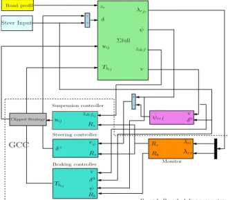
This strategy is summarized in the following imple-mentation scheme (see Fig. 1) including the vehicle’s model, the monitoring approach and the subsystems controllers. λrf r ˙ ψ zdef v uij Tbrj δ Steer Input zr v δ0 λrr λrl ˙ ψref + − Rs Rb Rs zdefij uij + + eψ˙ Rs δ+ v δ0 ˙ ψ Rb Tbrj Σfull Suspension controller Steering controller
Braking controller Monitor
Rs and Rb: scheduling parameters Road profil
GCC
Clipped Strategy
Fig. 1: Global chassis control implementation scheme. The paper is organized as follows:
section 2 presents the overview of the main contri-bution of the paper which is the coordination between semi-active suspension, steering and braking actuators, and the synthesis of different controllers to enhance ve-hicle performances and attitude. The control synthesis for the braking/steering subsystem (resp. suspension subsystem) and the performance analysis through fre-quency domain simulations are detailed in sections3 (resp.4).
In Section 5, time domain simulations are performed on a complex nonlinear full vehicle model equipped with semi-active suspension MRD. It also emphasizes the contribution of the proposed LPV strategy by comparing it to the LTI strategy. Conclusions and discussions are given in the last Section.
Paper notations:
For modeling and simulation purposes, the follow-ing vehicle parameters and notations are adopted. Throughout the paper: indices i = {f, r} and j = {l, r} are used to identify the vehicle front, rear and left, right positions respectively. Also, since the full vehicle model is used, some notations will appear. Index {s, t} holds for suspension and tire forces re-spectively.{x, y, z} holds for forces and dynamics in the longitudinal, lateral and vertical axes respectively.
Then let v = qv2
x+ v2y denote the vehicle speed,
Rij = R− (zusij − zrij) the effective tire radius,
m = ms + musf l + musf r + musrl + musrr the
total vehicle mass,δ = δd+ δ+ is the steering angle
(δd, the driver steering input and δ+, the additional
steering angle provided by steering actuator and Tbij
the braking torque provided by the braking actuator (see Section II).
II. A NEWGLOBALCHASSISCONTROLSTRATEGY:
SUPERVISION ANDSYNTHESIS
This section presents the main contribution of this study, namely, the multivariable Global Chassis Con-trol (GCC) involving front active steering, rear braking and semi-active suspension (see Fig.1). Such a strategy, preliminary introduced by the authors in previous works (see [16]), involves 2 monitoring parameters Rb andRs, used to evaluate the dangerousness of the
driving situation and to schedule the control actions.
Steering controller Braking controller Suspension controller Coordination strategy Monitoring system Renault Mégane Coupé
Fig. 2: General structure scheme
The main idea is to synthesize two controllers, one dedicated to the lateral dynamics and the other to the vertical dynamics, that will be coordinated thanks to the scheduling parameters Rb (braking) and Rs
(suspension and steering). The controllers synthesis is presented in the following sections.
A. Driving situation monitoring
The monitoring of the driving situation has been se-lected following [16] from the longitudinal slip ratio of the rear wheels (sij), since it considerably affects
the yaw stability and the car handling attitude.
• Braking monitor: Rb= min
j=l,r(rbj), (1)
is a function of the absolute value of the slip ratio (|srj|). rbj is defined as a relay (hysteresis
like) function:→ 0 when ’on’, → 1 when ’off’. The switch ’on’ (resp. ’off’) threshold iss+(resp
s−).
When the slipping is low, the vehicle is in a normal situation, hence Rb → 1. When the slip
ratio raises and becomes greater thans+, a critical
situation is detected, then Rb → 0. Since Rb is
function of the slip ratio,s+ ands− are chosen
according to the tire friction curve. Here (and in a general case),s+= 9% and s−= 8%, in order
to delimit the linear and peak tire friction force with the unstable part of the tire (see [17]).
B. Classification of the driving situations
Based on the previously defined driving situation monitor Rb, the other varying parameter Rs allows
to classify these driving situations depending on the dangerousness and on the degree of emergency under which the vehicle is running. This parameter Rs is
defined as follows: Rs =1 when1 > Rb> R2crit = Rb−R1crit R2 crit−R1crit whenR1 crit< Rb < R2crit =0 when0 < Rb< R1crit (2)
When Rb > R2crit(= 0.9), i.e. when a low slip
(< s−) is detected, the vehicle is not in an emergency situation andRsis set to1. When Rb< R1crit(= 0.7),
i.e. when a high slip occurs (> s+), a critical situation
is reached and Rs is set to 0. Intermediate values of
Rb correspond to intermediate driving situations.
The Rb and Rs varying parameters are used (as
de-tailed later in the design step) to schedule the use of the Active steering, Semi-Active suspension and Electro-Mechanical Braking actuators according to the driving situation and to optimize their operating range as described below, and summarized in Fig. 3.
Rb Normal Situation Intermediate Situation Critical Situation
Steering Braking Suspension
Emergency Level Of The driving Situation Comfort Objectives Smooth transition between performance Objectives Roadholding Objectives 0 Rs= 1 Steering action strongly Rs
Adaptation to the driving
Rb
Situations
More steering Less Braking
Rb→ 0 Braking action Allowed Rb→ 1 Braking action strongly Rs= 0 Steering action Fully Allowed penalized
penalized
Fig. 3: Actuators monitoring and scheduling strategy
Normal situation: (Rs = 1, Rb→ 0) the driving
cruise goes smoothly, (no emergency situations). Since there is no risk of wheel locking, asRb→ 0 the
rear braking torques is not limited. The semi-active
suspension is tuned in order to preserve the passengers comfort, without deteriorating the road holding (i.e soft suspension damping), thanks to the scheduling parameter Rs = 1. Also, since the driving situation
is safe, no corrective steering action is needed to stabilise the vehicle.
Intermediate situation: (Rs & , Rb%) As the
driving situation becomes dangerous, the values of the scheduling parameters Rs and Rb change.
The tire forces approach the non linear zone of the tire characteristic. As a result, the value of the monitor Rb starts to rise and the braking torques
are penalized to prevent the wheel locking. At the same time, the varying parameter Rs decreases and
an a corrective steering action is allowed to help the driver to overcome this situation. Also, the semi-active suspension characteristics are changed smoothly, from soft to hard, depending on the value ofRs, to further
improve the car road holding without deteriorating the passengers comfort.
Critical situation: (Rs= 0, Rb→ 1) When a
danger-ous situation is detected through the braking monitor Rb= 1 (in terms of longitudinal tire slip), the braking
torques are limited accordingly in order to bring back the forces into the linear stable zone of the tire char-acteristic. AsRs reaches zero, the maximum additive
steering angle is generated and the semi-active MR dampers are tuned to be "hard" in order to ensure a good roadholding (small wheel rebound). This will help the driver to overcome the critical driving situation and to prevent the vehicle from imminent accidents.
C. Global chassis controllers design synthesis
The scheme in Fig. 1 shows the proposed2-step GCC LPV/H∞ strategy. The first one is dedicated to the front steering/ rear braking controller, that aims at improving the yaw stability and the lateral dynamics. The other one corresponds to the4 semi-active MRD suspension system, to enhance the vertical behavior (comfort/roadholding performances of the car). It is worth noting that the coupling effects are handled through the scheduling parameterRsand thanks to an
"anti-roll" action of the semi-active suspension. The main strategy is to adapt the control action to the driving situation as previously presented in Fig.3, using a self-scheduled controller function of Rb and Rs.
This will be achieved thanks to a good coordination and communication between the actuators of Active front Steering, Electro-Mechanical rear Braking, and the Semi-Active MRD Suspension systems.
III. FIRST STEP:THE BRAKING/STEERING CONTROL PROBLEM FORMULATION
The LPV/H∞ controller synthesis for the brak-ing/steering subsystems is achieved, based on the ex-tended bicycle model.
A. Extended lateral bicycle vehicle model: control oriented
The model describes the lateral dynamics of the ve-hicle. It has been used in many studies in order to synthesize braking and steering control to enhance several dynamical behaviours such as the yaw rate, the lateral acceleration and the lateral sideslip dynamics (more details see [15]).
B. The LPV/H∞ braking/steering controller synthesis method:
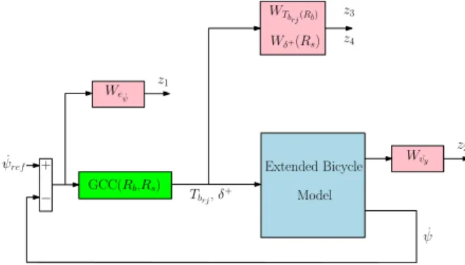
The following general control configuration (including gain scheduled weighting functions) is considered:
Extended Bicycle Model GCC(Rb,Rs) Weψ˙ WTbrj(Rb) Wδ+(Rs) ˙ ψref + − Wv˙y Tbrj, δ+ ˙ ψ z1 z2 z3 z4
Fig. 4: Generalized plant for braking/steering control synthesis.
where: Weψ˙ = 10
s/500+1
s/50+1, is used to shape the yaw
rate error (eψ˙ = ψ˙ref − ˙ψ) and W˙vy = 10−3,
attenuates the lateral acceleration. Also,WTbrj(Rb) =
Rbs/100$+1s/10$+1 , attenuates the yaw moment control
in-put according to the value of Rb and Wδ+(Rs) =
Rss/10κ+1s/κ+1 , attenuates the steering control input
ac-cording to the value ofRs.
where $ (resp. κ) is the braking (resp. steering) actuator cut-off frequency.
The controller is chosen to be scheduled by the varying parameters Rb and Rs (according to the
diagram given in Fig.3) in order to achieve the following objectives:
• Normal situation: The tire force is in the linear friction zone, i.e. there is no risk of wheel locking; so Rb → 0 and the weighting function gain of
WTbrjis chosen to be low. Therefore, the braking
control is allowed to stabilize the vehicle. At the
same time Rs = 1, the gain of the weighting
function on the steering control is high and no additive steering angle is necessary.
• Intermediate situation: When the driving
situ-ation becomes more dangerous, the gains of the weighting functions on the braking and steering actions change to cope with the needs for the vehicle stabilization. Indeed, the braking action is more and more reduced to avoid the wheels skidding, while a more corrective steering angle is supplied to help keeping the vehicle stable.
• Critical situation: When a high slip ratio is de-tected,Rb→ 1; the gain of the weighting function
is increased to deactivate the braking torques and to prevent the wheels from locking. Then, the value of the varying parameter Rs is set to 0,
the steering weighting function is not penalized any more and a maximum corrective action by the steering actuators is allowed to compensate for the lack of braking, and to preserve the handling and stability of the vehicle. This may help the driver to overcome the critical driving situations. The corresponding LPV generalized plant is modeled as: Σ(R(.)) : ˙x z y = A(Rs, Rb) B1(Rs, Rb) B2 C1(Rs, Rb) D11(Rs, Rb) D12 C2 0 0 x w u (3)
where x includes the state variables of the system and of the weighing functions, w = Fdy and
u = [δ+, T
brl, Tbrr] are the exogenous and control
inputs respectively;
z = [z1, z2, z3, z4] =
[Weψ˙eψ˙, W˙vy˙vy, WTbrj(Rb)Tbrj, Wδ+(Rs)δ
+] holds
for the controlled output, and y = ˙ψref(v) − ˙ψ is
the controller input, where ˙ψref(v) is provided by a
reference bicycle model.
Notice that, the LPV model (3) is here affine w.r.t the parametersRs andRb and can be described as a
polytopic system, i.e. a convex combination of the sys-tems defined at each vertex formed byPR(.), namely
Σ(R(.)) and Σ(R(.)). The controller is then a convex combination of 4 vertex controllers obtained at the min/max values ofRb/Rs. From the affine generalized
plant in Fig. 4, an LPV polytopic controller is designed in the framework of the quadratic stabilisation, as explained for instance in [18].
IV. SECOND STEP:THE SUSPENSION CONTROL PROBLEM FORMULATION
The control of the semi-active suspension system is synthesized using the classical 7-DOF vertical model (see [15]) in order to handle the trade-off between the chassis motion (comfort) and the roll one (han-dling). Here, a vehicle equipped with 4 MR semi-active dampers is considered. As explained in section
4.3, the MR damper is a non-linear component with dissipative capability used in automotive suspension control systems, where the damping property varies according to the applied magnetic field. Such a damper is able to provide adaptive performances in terms of comfort and road holding.
A. Full vertical vehicle model: control oriented This model includes the vertical dynamics of the chassis zs, the vertical motions of the wheels zusij,
the pitchφ and roll θ (more details in [15]).
B. LPV/H∞ suspension controller synthesis:
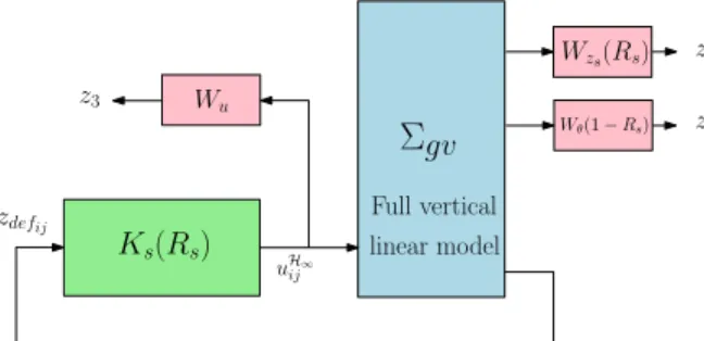
The control of suspension systems aims at enhancing the vertical dynamics of the vehicle in order to achieve frequency specification performances, see [8] and [19]. Here the control objectives are oriented towards bounce and roll motions, characterized by the frequency-domain weighting functions in theH∞ control framework (see Fig. 5).
Σ
gv Wu Ks(Rs) uH∞ ij z1 z2 zdefij z3 Wzs(Rs) Wθ(1− Rs) Full vertical linear modelFig. 5: Suspension system generalized plant.
where Wzs(Rs) = Rs
s2+2ξ11Ω11s+Ω112
s2+2ξ12Ω12s+Ω122 is shaped
in order to reduce the bounce amplification of the suspended mass (zs) between [0, 12]Hz, when Rs is
high.
Wθ(Rs) = (1− Rs)s
2+2ξ
21Ω21s+Ω212
s2+2ξ22Ω22s+Ω222 attenuates the
roll amplification in low frequencies, whenRs is low.
Wu= 3.10−2 is set to shape the control signal.
This control design schedules the use of the semi-active dampers and the vehicle performance as follows:
In Normal situation: Rs = 1, the semi-active
suspension control enhances the passenger comfort objectives by using a high gain of the weighting function on the chassis displacement zs. The
undesirable vibrations of the chassis are then absorbed by the MR semi-active dampers which are tuned to have a soft damping characteristic.
Intermediate situation: when the driving situation changes, the varying parameter Rs decreases, which
increases the weighting on the roll dynamics of the car caused by the lateral load transfers. Therefore the suspension control modifies the performance objectives from passenger comfort to roadholding. The LPV framework used in the proposed strategy ensures a smooth and efficient transition between these performance objectives while ensuring the stability conditions.
In Critical situation: Rs = 0, the semi-active
suspension control acts to further improve the roadholding. The weighting on the chassis motion is relaxed since the passenger comfort is no longer the priority, and a high penalization on the roll motion is set to reduce the load transfer that may lead to vehicle instability (close to accident).
The configuration of the proposed LPV/H∞ ensures the appropriate help to the driver by monitoring the driving situation and the related vehicle dynamics. The main purpose is to preserve the passenger safety and to help to overcome the different emergencies while facing such situations.
Remark 1:
The selection of the parameters of the weighting func-tions is a key step in H∞ control. Usually, they are chosen using empirical rules, thanks to the automotive engineers experience but it doesn’t guarantee any op-timal value for these parameters. Here, one follows the methodology described in [20] where a genetic algorithm was used to optimize the parameter’s values that minimize a criterion representative enough of the vehicle vertical performances in terms of comfort and roadholding.
According to Fig. 5, the following parameter dependent generalized plant (Σgv(Rs)) is obtained:
˙ξ z y = A(Rs) B1(Rs) B2 C1(Rs) D11(Rs) D12 C2 0 0 ξ w u (4) where ξ = [χvert χw]T is the state vector of
the system plus the state vector of the weighting functions;z = [z˜ 1z2z3]T;w = [z˜ rijFdx,y,zMdx,y]T;
y = zdefij; u = u
H∞
ij ,i = f, r and j = l, r; Fdz is
the vertical disturbance and Mdz is the disturbance
moment along thez-axis.
The LPV system (4) includes a single scheduling parameter (Rs) and can be described as a polytopic
system after some relaxations, i.e, a convex combina-tion of the systems defined at each vertex of a polytope defined by the bounds of the varying parameter. The LPV/H∞ suspension controller synthesis is ob-tained thanks to LMI’s resolution of the control
prob-lem following the mathematical development given in [21].
Remark 2: Since semi-active suspensions are consid-ered, the LPV controllers are clipped in order to cope with the damper constraints
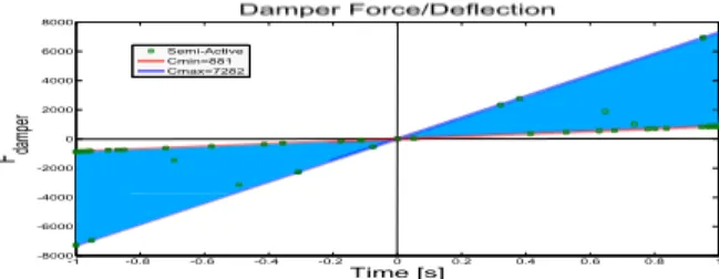
C. The semi-active suspension control implementation The application of the proposed LPV control to the considered semi-active suspension is achieved here, for simplicity, using the clipped strategy (see [8]). The Fig. 6 shows the experimental characteristics of the MR dampers obtained in collaboration with colleagues from ITESM, Monterrey, Mexico (see [22]). Given a deflection speed (˙zdef) and a desired controlled
damper force F∗, the clipped approach consists in
projecting F∗ onto the admissible force domain, if
necessary, to getF⊥ . F∗ 1 F⊥ 1 F2∗ F⊥ 2 F∗ 3= F⊥ 3 F [N ] ˙ zdef
Realistic MR damper force
Cmax= 7282
Cmin= 881
Fig. 6: Illustration of projection principle of the semi-active controlled damper model (F∗
1 andF2∗are out of
the allowed area and F∗
3 is inside)+ the MR damper
force with bi-viscosity "Cmin = 881, Cmax = 7282"
(for more details see [23])
V. SIMULATION
In this section, the complete and validated non linear model of the vehicle used for simulation purpose is recalled (a first version of this model is available in [16]). Then, 2 different simulation scenarios are presented and the corresponding results are analysed.
All along the paper results, the proposed LPV/H∞ VDC, denoted as ’LPV’, will be analyzed and com-pared to the Renault Mégane Coupé car (without control denoted "Open Loop") and, for sake of com-pleteness, with the standard LTI/H∞ design of both active steering/ braking controller and semi-active sus-pension controller (without scheduled gains), denoted as ’LTI’, which was achieved by solving the previous H∞problems with the values of the varying parameter
frozen at Rs = 0.1 and Rb = 0.9 (near a critical
situation).
A. The full non linear vehicle model of a real Renault Mégane Coupé
The parameters used for the simulation were obtained by experimental identification of the physical param-eters of the "Renault Mégane Coupé" at the MIPS laboratory in Mulhouse, France.
Also, the non linear model used for the simulations purposes was validated by an experimental procedure made on a real Renault Mégane Coupé, through a Moose test performed on a real track.
B. Simulation results: a first scenario
In this case, simulation results are presented to em-phasize the improvements of LPV closed-loop control (denoted " CL LPV semi-active") compared to the open loop results (denoted as "Open Loop") and, for sake of completeness, to the standard LTI/H∞ design of both Active Steering/ Braking controller and semi-active suspension controller (without scheduled gains),(denoted as "CL LTI", which was achieved by solving the previous H∞ problems with the values of the varying parameters frozen at Rs = 0.1 and
Rb= 0.9.
The following scenario is considered. When the vehicle runs at 100km/h in straight line, the following events occur: fromt = 0.5s to t = 1s: a 5cm bump on the left wheels, then the driver perform a double line change fromt = 2s to t = 6s, and finally another 5cm bump on the left wheels, during the manoeuvre,t = 3s to t = 3.5s. a lateral wind occurs at vehicle’s front, generating an undesirable yaw moment, is consideredt = 2.5s to t = 3s In this scenario, for the robustness analysis, the road is considered as wet (µ = 0.5, the road adherence parameter), which reduces the road/tire adhesion and the lateral tire contact forces.
The resulting monitoring signals Rb (see Eq.(1)) and
Rs (see Eq.(2)) are shown in Fig. ?? and justify the
LPV framework of the strategy.
Fig. 7: Monitoring signals
The varying parametersRb and Rs allow to activate,
limit or deactivate the control action when required (for braking and steering actuators). Let recall that theRs scheduling parameter depends on the value of
Rb, which itself depends on the slip ratio dynamics.
the behavior of the vehicle subject to critical driving situations. They will be used to provide the driver with the necessary assistance, through the steering, braking and suspension subsystems.
Fig. 8: Yaw rate
1) Lateral dynamics behavior analysis: It can been see from Fig. 8 that the proposed LPV/H∞ strategy enhances better the lateral dynamics, here, the vehicle yaw tracking. Compared to the LTI/H∞ controller, it gives good results in terms of vehicle lateral stability. Remark 3: Simulations using an extended bicycle model with the driver input have given the "ideal" reference vehicle to be tracked by the vehicle (black dashed line, see Fig. 8). It helps to compare and to emphasize the improvements brought by the proposed LPV/H∞strategy
Fig. 9: Vertical chassis displacementzs
2) Vertical dynamics behavior analysis: The vertical motion of the chassis is shown in Fig. 9. The LPV/H∞ controller improves the vertical dynamics better than the LTI/H∞ one does. The chassis displacement is considerably reduced by the proposed strategy. This enhances the passengers comfort while driving on uneven roads.
Fig. 10 represents the improvement brought in term
Fig. 10: Roll motion of the chassis θ
of the load transfer mitigation. The roll motion is well
attenuated which, in addition to enhance the vehicle stability, ensures a good road handling of the vehicle running in dangerous driving situations. It is seen that the use of the semi-active suspension control in the coordinated "LPV/H∞" strategy (with hierarchical activation of the different actuators depending on the driving situations needs) gives better results than in the "LTI" case.
3) Actuators dynamics behavior analysis: In addition to enhancing the vehicle various dynamics, the proposed LPV/H∞ improves the use of the actuators (electromechanical braking, active steering and semi-active suspensions) considered for the car under study. The following figures show interesting results for the actuators activation.
Fig. 11 and Fig. 12 show the braking torques
Fig. 11: Rear right Break-ing torque.
Fig. 12: Rear left Breaking torque.
provided by the vehicle to perform the previously defined scenario. The braking torques provided by the LPV/H∞ controller are depicted in red. The torques are clearly much lower than those provided in the LTI controller case (blue curves), that saturate. Moreover the use of the LPV/H∞strategy avoids wheel locking: Fig. 12 shows that for the LTI case, the longitudinal slip ration λrl reaches the 100% value which means
that the left rear wheel is locked.
Fig. 13: Steer control input
Therefore the "LPV coordination strategy" can help the driver to keep the vehicle stable with a minimum effort. Indeed the steer control considerably decreases in the "LPV" case, compared to the "LTI" case, and is activated only when the driving situation is dangerous enough.
-1 -0.8 -0.6 -0.4 -0.2 0 0.2 0.4 0.6 0.8 1 -8000 -6000 -4000 -2000 0 2000 4000 6000 8000 Time [s] F damp er Damper Force/Deflection Semi-Active Cmin=881 Cmax=7282
Fig. 14: Damper force/deflection
characteristic of the controlled semi-active suspension. As explained previously, the semi-activeness is obtained by the "Clipped Strategy" that takes into account the min and max damping limits of the MR dampers, namelyCmin= 881 and Cmax= 7282.
Remark 4: In the previous simulations, the LTI control strategy gives good results. However, since the rear wheels lock during the manoeuvre (see Fig. 12) leading to a very high risk of loss of manoeuvrability and safety degradation, the LPV control appears to be a very efficient way to deal with the braking issues. Moreover, it enhances performances and stability, us-ing the previously presented integrated control strategy. Furthermore, the LPV controller uses the actuators of braking, steering and suspension in a coordinated way to enhance the overall vehicle dynamics and to cope better with the actuators characteristics and limitations. The improvements brought by the proposed strategy compared to the LTI control case are quantified in Ta-ble. I by calculating the RMS (Real Mean Square value of the signals) values of the different car dynamics signals.
Signals improvement % Vehicle dynamics
zs 11 Chassis displacement θ 13 Roll motion ˙ ψ 19 Yaw rate ˙ y 32 Lateral acceleration Tbrl;Tbrr 68; 74 Braking torques δ 86; Steering angle F sij 27, 31, 23; 28 Suspension forces
TABLE I: Performances evaluation
The comparison shown in this Table. I proves the efficiency of the proposed solution for this driving scenario.
C. Simulation results: a second scenario.
This scenario uses experimental data obtained for model identification. Indeed, a test (of the real uncontrolled Renault Mégane Coupé car) was first performed by a professional driver on a real race track. This circuit includes a left bend and then an obstacle avoidance (emergency situation) to determine how well a vehicle evades a suddenly appearing
obstacle.
In the considered simulation case, the focus is put on the "Moose" test only (performed at a velocity of 90km.h−1) in order to assess the efficiency of the
designed controllers for obstacles avoidance.
The "driver" inputs (i.e. the steering angle and the longitudinal speed) are considered as external inputs of the NL closed-loop model for the simulation of the LPV control. The closed-loop simulation results obtained from real input data (denoted here as "LPV VDC") are then compared with the experimental ones (denoted here as "Measurement passive vehicle").
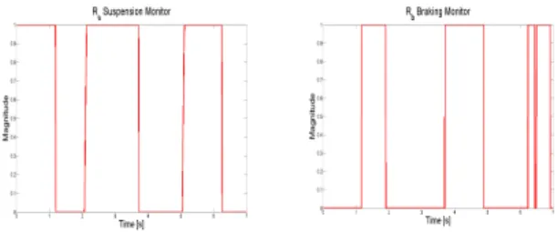
The resulting varying parameters, Rs and Rb, that
schedule the coordination of the 3 actuator’s con-trollers (Semi-Active Suspension, Active Steering and Electro-Mechanical Braking) are shown on Fig. ??. These parameters have complementary values, which is coherent with the previously presented monitoring strategy. 20 25 30 35 40 45 50 55 60 0 0.2 0.4 0.6 0.8 1 t [S] Magnitude Rs 20 25 30 35 40 45 50 55 60 0 0.2 0.4 0.6 0.8 1 t [S] Magnitude Rb
Fig. 15: Monitoring Rs andRb signals
20 25 30 35 40 45 50 55 60 −0.8 −0.6 −0.4 −0.2 0 0.2 0.4 0.6 0.8 t [S] ψdt
Yaw rate [rad/s2] Measurement passive vehicle
LPV VDC
Fig. 16: Yaw rate ˙ψ
Remark 5: The passive vehicle dynamical behaviours presented in this section were measured on the real vehicle (Renault Mégane Coupé) while performing this scenario on a real circuit path.
Fig. 16 shows the yaw rate behavior of the vehicle using the proposed LP V /H∞ control compared to
the passive vehicle behavior. One can notice that the yaw rate dynamics of the vehicle are well improved even if the vehicle is running with a quite high velocity (90km.h−1) on the left bend when avoiding the obstacle.
Fig. 17 shows the improvement of the roll velocity. Indeed, using the designed LP V /H∞ controllers
20 25 30 35 40 45 50 55 60 −0.6 −0.4 −0.2 0 0.2 0.4 0.6 0.8 t [S] θdt
Roll velocity [rad/s]
Measurement passive vehicle LPV VDC
Fig. 17: Roll velocity of the chassis ˙θ
that coordinate the use of the semi-active suspension, steering and braking, the roll motion considerably reduces (47% less than that of the passive car). It is obvious that the vertical dynamics are better enhanced using an LP V /H∞ robust controller in emergency
situations. 20 25 30 35 40 45 50 55 60 −150 −100 −50 0 50 100 150 t [S] Angle (Deg °)
Steering wheel mesurement
20 25 30 35 40 45 50 55 60 −3 −2 −1 0 1 2 3 t [S] Angle (Deg °)
Additive steering angle from the controller
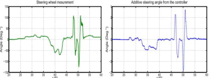
Fig. 18: Steering wheel angleδ0 (left) and corrective
steering angle from the controllerδ+ (right)
Fig. 18 shows the measured rotation angle of the steering wheel that the driver generates to perform the considered driving scenario (left), and, right, the corrective steering angle that the controller supplies to help the driver to ensure the vehicle stability and manoeuvrability. This corrective steering angle is directly applied on the wheel (not on the steering wheel).
Notice that the steering ratio of the car, which is the rotation angle of a steering wheel divided by the steer angle of the wheels, is around 10 : 1 to 20 : 1 depending on the car’s type (commercial, race, sport...). This means that the corrective steering angle’s effect is very important.
VI. CONCLUSION
In this paper, a global chassis control strategy has been proposed, involving active steering, electromechanical braking and semi-active suspension. This strategy was shown to enhance the vehicle dynamical behavior subject to critical driving situations. In this framework, the LPV approach plays a major role to efficiently schedule the use of these actuators. Indeed the originality of the proposed approach is first concerned by the coordinated use of these 3 types of actuators, and second by their hierarchical activation, depending
on the driving situations, which allows to reach the performance objectives.
Another advantage of the LPV methodology (compared to classical LTI controllers) is the limitation of the braking actuation in critical situations to avoid wheel locking and skidding, and its coordination with active steering and semi-active suspension controllers, leading to vehicle stability and road handling improvements.
Simulation results, obtained from experimental input data, and performed with a validated complex nonlinear vehicle model, have assessed the performances of the proposed approach. However, a complete control validation step requires a set of experiments performed on a test car equipped with the considered actuators. The real implementation of the control algorithm might lead to several problems that do not occur in simulation: for instance real-time constraints. This could be handled further in an experimental study.
REFERENCES
[1] M. Denny, “The dynamics of antilock brake systems,” Euro-pean Journal of Physics, vol. 26, pp. 1007–1016, 2005. [2] M. Tanelli, R. Sartori, and S. Savaresi, “Sliding mode
slip-deceleration control for brake-by-wire control systems,” in Proceedings of the 5th IFAC Symposium on Advances on Automotive Control (AAC), Aptos, California, August 2007. [3] T. Acarman, “Nonlinear optimal integrated vehicle control
using individual braking torque and steering angle with on-line control allocation by using state-dependent riccati equation technique,” Vehicle System Dynamics, vol. 47, pp. 155–177, 2009.
[4] C. Poussot-Vassal, O. Sename, L. Dugard, and S. M. Savaresi, “Vehicle dynamic stability improvements through gain-scheduled steering and braking control,” Vehicle System Dynamics, vol. 49:10, pp. 1597–1621, March 2011. [5] M. Doumiati, O. Sename, J.-J. Martinez-Molina, L. Dugard,
and C. Poussot-Vassal, “Gain-scheduled lpv /H∞controller
based on direct yaw moment and active steering for vehicle handling improvements,” in Proceedings of the 49th IEEE Con-ference on Decision and Control (CDC’10), Atlanta, Georgia, December 2010.
[6] C. Poussot, O. Sename, S. Fergani, M. Doumiati, and L. Dugard, "Global Chassis Control Using Coordinated Con-trol of Braking/Steering Actuators", Chapter9, pp.237-265, in Robsut Control And Linear Varying Parameter Approaches: Application to Vehicle Dynamics, O. Sename, P. Gáspár, and J. Bokor, Eds. Springer, 2013.
[7] C. Poussot-Vassal, C. Spelta, O. Sename, S. Savaresi, and L. Dugard, “Survey and performance evaluation on some auto-motive semi-active suspension control methods: A comparative study on a single-corner model,” Annual Reviews in Control, vol. 36, no. 1, pp. 148 – 160, 2012.
[8] S. Savaresi, C. Poussot-Vassal, C. Spelta, O. Sename, and L. Dugard, Semi-Active Suspension Control for Vehicles. El-sevier - Butterworth Heinemann, 2010.
[9] M. Jonasson and F. Roos, “Design and evaluation of an active electromechanical wheel suspension system,” Mechatronics, vol. 18, no. 4, pp. 218–230, 2008.
[10] S. Savaresi and C. Spelta, “Mixed sky-hook and ADD: Ap-proaching the filtering limits of a semi-active suspension,” ASME Transactions: Journal of Dynamic Systems, Measure-ment and Control, vol. 129, no. 4, pp. 382–392, 2007.
[11] A. L. Do, C. Spelta, S. Savaresi, O. Sename, L. Dugard, and D. Delvecchio, “An LPV control approach for comfort and suspension travel improvements of semi-active suspension systems,” in Proceedings of the 49th IEEE Conference on Decision and Control (CDC), Atlanta, GA, December 15-17, 2010, pp. 5660–5665.
[12] J.-S. Lin and W.-E. Ting, “Nonlinear control design of anti-lock braking systems with assistance of active suspension,” IET control theory & applications, vol. 1, no. 1, pp. 343–348, 2007.
[13] “Hierarchical fuzzy-neural control of anti-lock braking system and active suspension in a vehicle,” Automatica, vol. 48, no. 8, pp. 1698 – 1706, 2012.
[14] S. Fergani, O. Sename, and L. Dugard, “A LPV/H∞ global
chassis controller for performances improvement involving braking, suspension and steering systems,” in Proceedings of the 7th IFAC Symposium on Robust Control Design, Aalborg, Denmark, June 2012.
[15] ——, “Performances improvement through an LPV/H∞
con-trol coordination strategy involving braking, semi-active sus-pension and steering systems,” in Proceedings of the 51th IEEE Conference on Decision and Control (CDC), Maui, Hawaii, USA, December 2012.
[16] C. Poussot-Vassal, O. Sename, L. Dugard, P. Gáspár, Z. Szabó, and J. Bokor, “Attitude and handling improvements through gain-scheduled suspensions and brakes control,” Control Engi-neering Practice, vol. 19, no. 3, pp. 252 – 263, 2011. [17] W. Milliken and D. Milliken, Race car vehicle dynamics,
S. of Automotive Engineers, Ed. SAE, 1995.
[18] P. Apkarian, P. Gahinet, and G. Beker, “Self-scheduled H∞
control of linear parameter-varying systems: A design exam-ple,” Automatica, vol. 31, no. 9, pp. 1251–1262, 1995. [19] C. Poussot-Vassal, O. Sename, L. Dugard, R.
Ramirez-Mendoza, and L. Flores, “Optimal Skyhook control for semi-active suspensions,” in Proceedings of the 4th IFAC Symposium on Mechatronics Systems, Heidelberg, Germany, September 2006, pp. 608–613.
[20] A. L. Do, O. Sename, and L. Dugard, “An LPV control approach for semi-active suspension control with actuator constraints,” in Proceedings of the IEEE American Control Conference (ACC), Baltimore, Maryland, USA, June 30 - July 2 2010, pp. 4653 – 4658.
[21] C. Scherer, “Mixed H2/H∞ control for time-varying and
linear parametrically-varying systems,” International Journal of Robust and Nonlinear Control, vol. 6, no. 9-10, pp. 929– 952, November 1996.
[22] J. de J. Lozoya-Santos, R. Morales-Menendez, R. Ramirez-Mendoza, J. C. Tudón-Martinez, O. Sename, and L. Dugard, “Magnetorheological damper an experimental study,” Journal of Intelligent Material Systems and Structures, vol. 23, no. 11, pp. 1213–1232, 2012.
[23] A. L. Do, J. de J. Lozoya-Santos, O. Sename, L. Dugard, R. A. Ramirez-Mendoza, and R. Morales-Menendez, “Modélisation et commande LPV d’un amortisseur magnéto-rhéologique,” in Proceedings de la Conférence Internationale Francophone d’Automatique, Nancy, France, June 2-5 2010.