HAL Id: hal-01022000
https://hal.inria.fr/hal-01022000
Submitted on 10 Jul 2014HAL is a multi-disciplinary open access archive for the deposit and dissemination of sci-entific research documents, whether they are pub-lished or not. The documents may come from teaching and research institutions in France or abroad, or from public or private research centers.
L’archive ouverte pluridisciplinaire HAL, est destinée au dépôt et à la diffusion de documents scientifiques de niveau recherche, publiés ou non, émanant des établissements d’enseignement et de recherche français ou étrangers, des laboratoires publics ou privés.
Adaptable Synchronous Detection for the SHM of
Composite Component: Autonomous FPAA
Architecture on Polyimide Film
Sabeha Fettouma Zedek, Catalin Codreanu, Andrés Belisario-Briceño,
Jean-Yves Fourniols, Christophe Escriba, Thierry Camps, Raoul François
To cite this version:
Sabeha Fettouma Zedek, Catalin Codreanu, Andrés Belisario-Briceño, Jean-Yves Fourniols, Christophe Escriba, et al.. Adaptable Synchronous Detection for the SHM of Composite Compo-nent: Autonomous FPAA Architecture on Polyimide Film. EWSHM - 7th European Workshop on Structural Health Monitoring, IFFSTTAR, Inria, Université de Nantes, Jul 2014, Nantes, France. �hal-01022000�
A
DAPTABLES
YNCHRONOUSD
ETECTION FOR THESHM
OF COMPOSITECOMPONENT
:
A
UTONOMOUSFPAA
ARCHITECTURE ONP
OLYIMIDEF
ILMS. F. Zedek1,2, C. Codreanu1,2, A.Belisario1,3, J-Y. Fourniols1,2, C. Escriba1,2, T. Camps1,3, R. Francois1,2
1
CNRS, LAAS F-31077 Toulouse
2
Université de Toulouse ; INSA F-31077 Toulouse
3
Université de Toulouse ; UPS F-31077 Toulouse
Abstract
— Structural Health Management strategies usually involve monitoring complex components, during their working life. Carbon fiber reinforced polymer components are becoming more and more used, throughout the structural engineering fields, because of their superior mechanical properties. Moreover, due to their construction, these materials open the path for new “smart” components, with integrated sensors and monitoring capabilities. Flexible circuits are essential in this context. In order to adapt to complex geometries, sensors and their connectivity have to be flexible and as un-intrusive as possible.
Following previous work, aimed at inserting sensors with flexible connectivity in between the sheets of carbon fibers, we conceived and implemented a reconfigurable acquisition system that can be easily adapted to perform strain measurements in various EM5 noise conditions. This paper presents a comparison between three circuits dedicated to strain measurement using a commercial strain gauge and flexible connectivity on Kapton2. The first circuit consists of a classic Wheatstone bridge under continuous voltage. The second uses the synchronous detection principle with classic circuits and functions. The third innovates upon the synchronous detection principle by implementing several functions in a reprogrammable analog chip called FPAA (Filed Programmable Analog Array).
The analysis of these circuits shows the added value of using reconfigurable devices with flexible connectivity and sensors in order to provide a universal solution for the monitoring of complex components.
Index Terms— FPAA1, Kapton2, SHM3, Strain Gauge, Synchronous detection, CFRP6.
INTRODUCTION
tructural Health Monitoring usually refers to the process of implementing a damage detection strategy for aerospace, civil or mechanical engineering [1]. The human being is surrounded by buildings, bridges and complex structures which have to be safe for use. In order to comply with safety regulations several techniques have been developed for monitoring these structures throughout their lifetime.
Almost all private and government industries want to detect damage in their products as well as in their manufacturing infrastructure at the earliest stage possible. Such detection requires these industries to perform some form of SHM and is motivated by the potential life gain, safety and economic impact of this technology S
[1].
Strain gauges are widely used for SHM in civil engineering because of their low cost, good sensitivity and simple usage. They exist in different sizes, forms and configurations, allowing the measure of strain and torsion. They are usually implemented in thin polymer films and are un-intrusive.
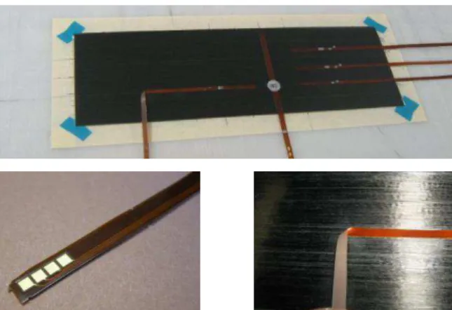
Previous work [4] has shown the feasibility of inserting sensors with Kapton connectivity in between the carbon fiber layers of a CFRP component. The circuits fared well during the high temperature molding process and the sensors were exploitable. The Kapton connectivity also withstands folding, allowing the creation of complex paths through a component. Figure 1 shows a pre-mold setup, with sensors and flexible connections placed on the second layer of carbon fibers, before they are covered with 8 more layers and molded at high temperature.
Figure 1: Flexible circuits inserted in between the layers of carbon fibers before molding. Also shown in the bottom left are the external connection pads. In the bottom right is shown the Kapton folding.
Using the gauges to monitor strain applied to the board requires a dedicated circuit capable of transforming a small change in electrical resistance into a voltage level. The starting block of this circuit is the Wheatstone bridge under continuous voltage. This circuit is the first one we created and analysed in order to have a reference set of characteristics. An improvement over the continuous voltage setup involves working at a high frequency (100kHz). This shifts the working spectrum away from 0 Hz and into an area where the sensor will be less sensitive to noise. The synchronous detection was implemented with classic components and with a reprogrammable analog chip. These two circuits were tested and benchmarked against each-other and against the Wheatstone bridge under continuous voltage.
For testing purposes we constructed an experimental bench using a strain gauge glued onto a carbon fibre rod. The rod is fixed at one end onto a stable support, as shown in figure (2)
Figure 2: Experimental setup with the sensor shown in red.
The following recordings of free oscillations were made during a step release test using this bench.
EWSHM 2014 - Nantes, France
1 Implementation of the proposed circuits
1.1 The Wheatstone bridge under continuous voltage
This type of bridge is widely used for the measurement of sensors [2]. As shown in the figure below the strain gauge is placed in one of the four branches of the bridge. Its nominal resistance is 121Ω and a trimmer was used in parallel on the left hand side in order to precisely balance the bridge (not shown in the figure).
Figure 3 : Schematic of a Wheatstone bridge under continuous voltage.
Once the bridge is properly balanced, VA = VB where:
) /( ) /( 4 3 4 1 R R R E V R R R E V B S G S G A
A small change RSG caused by mechanical strain produces an offset:
S G S G B A M R R E R V V V 1
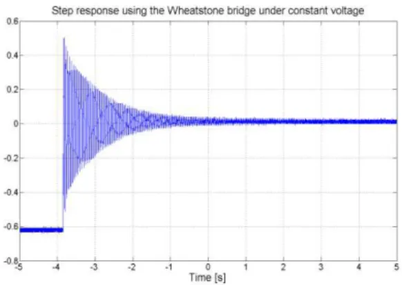
This signal is extracted using an INA128 instrumentation amplifier. It is amplified by a factor of 500 using low-noise amplifiers. The final stage is a low-pass second order filter with a cut-off frequency of 2.5 kHz.
Figure 4 shows a recording of the free oscillations of the component under test during a step release test using this circuit.
Figure 4 : Step response using the Wheatstone bridge under constant voltage.
(1) (2)
1.2 The synchronous detection circuit
The synchronous detection is a signal processing technique for extracting a weak signal flooded in noise. The following block diagram details its main components.
Figure 5 : Schematic of the synchronous detection system
The useful signal is shifted to a frequency, imposed by the wave generator Fm, where the noise level is lower. The modulated signal is amplified; filtered and then demodulated. After the multiplier, the low-pass filter removes the 2Fm component.
In order to extract the sensor’s signal, we use a modified version of the Wheatstone bridge, the Maxwell Bridge. Capacities were introduced in parallel to each resistance on the left hand side of the bridge (not shown on figure 6) in order to balance the complex impedances of the components. Again, the bridge’s offset is directly proportional to the change in gauge resistance. Due to the complex equivalent impedance, the signal VM = VA - VB changes both its amplitude and phase.
Figure 6 : Circuit schematic for the synchronous detection
Again, we used an INA128 instrumentation amplifier to extract the VM signal. There is a pre-amplification step by a factor of 10 before filtering. Following filtering the signal is again amplified by a factor of 50 and filtered in order to remove frequencies above 2.5 kHz.
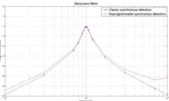
Since our objective is to compare the discrete architecture with the reprogrammable architecture, we sized the filters such that the circuits are similar in terms of bandwidth. The following figure shows the band pass of the filter created for this circuit and the one programmed in the following circuit :
Figure 7 : Band pass filters magnitudes
EWSHM 2014 - Nantes, France
Following is the release step response recorded with this circuit.
Figure 8 : Step response using the synchronous detection circuit
1.3 Reprogrammable synchronous detection circuit
As seen previously, one of the key parameters of the synchronous detection system is Fm, the work frequency. This is usually chosen depending on the strain gauge’s noise profile but external
interferences must also be taken into account. Changing this frequency in the previous architecture implies modifying a big part of the design since it requires changing the wave generator and the band pass filter.
The re-programmable analog chip FPAA offers an excellent solution to this problem. FPAA stands for Field Programmable Analog Array. It can incorporate both the oscillator and the band pass filter and both can be changed programmatically without modifying the circuit board.
Furthermore, since the analog multiplier is one of the most expensive components on the board, it’s worthwhile to remove it. The FPAA is capable of incorporating a multiplier CAM with equivalent performances. CAM stands for Configurable Analog Module.
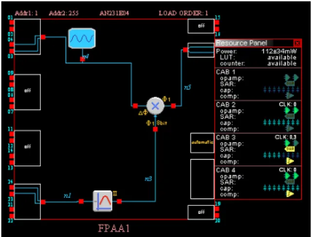
FPAA is an analog reprogrammable device based on operational amplifiers and switch capacitors distributed in four Configurable Analog Blocs, CABs. Figure 9 is a diagram of the internal
architecture of the AN231E04. It can be used for low power circuits in many electronic applications for filtering and adaptable design. In our application, we used it for signal conditioning.
Figure 9 : Architectural overview of the AN231E04 device with dynamic re-configurability [3] Anadigm provides the AnadigmDesigner®2, a software package for the users to configure, simulate and program their FPAA boards. We used the AN231E04 and we configured it with the following schematic:
Figure 10 : Programmed circuit using the AnadigmDesigner suite.
For the band pass filter we used the included “Filter Designer” and we chose the following parameters:
Experimentally we measured the magnitude graph shown in figure 7. This band pass filter occupied two operational amplifiers, eight switched capacitors in one CAB [2] and it requires 55±17 mW of power. This leaves enough room in the CABs for two additional filter CAMs.
The programmed FPAA is inserted into the synchronous detection circuit as shown on the following schematic:
Figure 11 : Synchronous detection integrating the reprogrammable circuit.
TABLEI
PASS BAND FILTER PARAMETERS
CENTER FREQUENCY 100 KHZ
Pass band width 10 kHz
Pass band gain 0 dB
Pass band ripple 1 dB
Stop band attenuation 14 dB
EWSHM 2014 - Nantes, France
The step response of the experimental setup is shown in the following figure:
Figure 12 : Step response using the reprogrammable synchronous detection circuit.
1.4 Noise analysis
Strain gauges are mainly used for long term surveillance of quasi-static low-amplitude
deformations. Thus they must be stable in time and have as little low frequency noise as possible. One of the main advantages of the synchronous detection system is the improved signal/noise ratio. In order to quantify this we measured the noise power spectrum. Figure 13 shows the results for the three circuits under test:
Figure 13 : Noise power density spectrum
As expected, the noise level for the synchronous detection circuit is lower than the one obtained with the bridge under constant voltage. On the other hand, using the reprogrammable system
introduces more noise and cancels the improvements achieved by the synchronous detection. At low frequencies ( < 1 Hz ), the noise traces have the same shapes but using the FPAA removes the stray frequencies observed for the two previous circuits. The noise level could be further reduced by directly integrating the FPAA onto the printed circuit board instead of linking with the evaluation board.
1.5 Power ratings
The following table shows the measured consumptions of the three circuits under test:
Passing from the Wheatstone bridge to the synchronous detection circuit the power consumption increases slightly due to the addition of several active components. As shown by the noise spectrum, this is a good compromise.
Using the reprogrammable circuit requires three times more power. This is due to the addition of several active components required by the multiple interfaces with the FPAA, but the biggest power consumers are the auxiliary systems present on the development board ( USB controller, RS232 programmer, EEPROM, PIC16F876A ) which are not mandatory for our application.
Conclusions
In our work we demonstrated the feasibility of implementing synchronous detection using a reprogrammable analog chip. This brings many advantages in terms of design adaptability: the working frequency can be easily changed, the bandwidth of the filters can be adjusted to comply with a specific need, additional functions can be programmed into the FPAA. The main drawbacks of using the FPAA are the noise level and the power consumption. The noise level can be improved by directly integrating the FPAA onto the circuit board. Also power consumption can be reduced by eliminating several auxiliary systems. Furthermore, changing the design so that it works on an asymmetric 0 – 5V supply and exploiting the fully differential in-out of the FPAA, could help reduce power consumption by a factor of 2.
Flexible circuits will change structural engineering by allowing sensors and circuitry to be directly integrated into the building blocks of mechanical systems. Reconfigurable circuits will play a key role in this technological advance by smoothing the path from the sensors to the data processing and the monitoring strategies which are required to ensure the proper operation of increasingly complex systems.
Acknowledgment
We take this opportunity to thank we would like to thank Mr. P. Marcoul, working with us here at LAAS-CNRS, for routing the circuits and fabricating the printed circuit boards.
References
[1] Charles R FARRAR, Keith WORDEN , “Structural Health Monitoring a Machine Learning Perspective” , ISBN 987-1-119-99433-6, J. Peters, Ed. John Wiely & Sons, 2013, pp. 3.
[2] Anadigm the dpASP. Dynamically programmable analog signal processing. http://www.anadigm.com/ . [3] Structural health Monitoring System based on Strain gauge enabled wireless Sensor Nodes.
[4] M. Torres, B. Douchin, F. Collombet, "Valeur ajoutée d’une encapsulation de capteurs silicium pour l’instrumentation à cœur des structures composites", Comptes Rendus des JNC 17 (2011)
TABLEI
POWER RATINGS FOR THE PRESENTED CIRCUITS
CIRCUIT TOTAL
POWER
Continuous voltage 231 mW
Classic synchronous detection 242 mW Reprogrammable synchronous
detection
728 mW
EWSHM 2014 - Nantes, France
![Figure 9 : Architectural overview of the AN231E04 device with dynamic re-configurability [3]](https://thumb-eu.123doks.com/thumbv2/123doknet/14424141.513860/6.892.268.635.745.1008/figure-architectural-overview-an-e-device-dynamic-configurability.webp)