HAL Id: hal-02533723
https://hal.archives-ouvertes.fr/hal-02533723
Submitted on 6 Apr 2020
HAL is a multi-disciplinary open access archive for the deposit and dissemination of sci-entific research documents, whether they are pub-lished or not. The documents may come from teaching and research institutions in France or abroad, or from public or private research centers.
L’archive ouverte pluridisciplinaire HAL, est destinée au dépôt et à la diffusion de documents scientifiques de niveau recherche, publiés ou non, émanant des établissements d’enseignement et de recherche français ou étrangers, des laboratoires publics ou privés.
Code Shift Keying: Prospects for Improving GNSS
Signal Designs
Axel Javier Garcia Peña, Marion Aubault-Roudier, Lionel Ries, Marie-Laure
Boucheret, Charly Poulliat, Olivier Julien
To cite this version:
Axel Javier Garcia Peña, Marion Aubault-Roudier, Lionel Ries, Marie-Laure Boucheret, Charly Poul-liat, et al.. Code Shift Keying: Prospects for Improving GNSS Signal Designs. Inside GNSS, Inside GNSS Media LLC, 2015, 10 (6), pp.52-62. �hal-02533723�
OATAO is an open access repository that collects the work of Toulouse
researchers and makes it freely available over the web where possible
Any correspondence concerning this service should be sent
to the repository administrator:
[email protected]
This is an author’s version published in: https://oatao.univ-toulouse.fr/22321
To cite this version:
Garcia Peña, Axel Javier and Aubault-Roudier, Marion and Ries,
Lionel and Boucheret, Marie-Laure and Poulliat, Charly and Julien,
Olivier Code Shift Keying: Prospects for Improving GNSS Signal
Designs. (2015) Inside GNSS, 10 (6). 52-62. ISSN 1559-503X
T
he constant growth and evolu-tion of the posievolu-tioning, naviga-tion, and timing (PNT) market generate demands for more and more added-value applications and services relying on GNSS signals, with expecta-tions for improved accuracy and avail-ability. Some services may also rely on added-value content other than naviga-tion messages, for example, higher data volume with less latency, such as the data carried by satellite-based augmentation system (SBAS) services and the Galileo Commercial Service.Among the many drivers that could be considered for possible future GNSS signals, those addressing the data com-ponent (higher rate, improved availabil-ity, and so forth) may be of particular interest. Although these drivers
signifi-cantly affect the design and performance of GNSS signals, thus calling for specific attention, their implementation may not necessarily require innovative technical solutions.
Nevertheless, alternative or innova-tive approaches may conceivably pro-vide better or different trade-offs of the various drivers, requirements, and con-straints, than the existing ones. Novel approaches should therefore be explored, and their adaptation to GNSS assessed, either to gain understanding and raise technical maturity — the Technology Readiness Level or TRL — so that these approaches become suitable candidates for future design, or to confirm that current solutions still provide the most appropriate trade-off.
One such example could be the anal-ysis of implementations to transport data bits on GNSS signals. The classi-cal approach consists of applying the equivalent bit or encoded symbol value sign (+1 or -1) directly onto the pseudo-random noise (PRN) waveform. Tradi-tionally, this technique has been iden-tified with BPSK or BPSK modulation, in reference to the non-return-to-zero BPSK (NRZ-BPSK) scheme, although this technique could also be applied to xBOC (binary offset carrier ) signals: BOC, alternative BOC (ALTBOC), mul-tiplexed BOC, and so on.
This article presents the code shift keying (CSK) modulation
principle and highlights some of its specific features related to
demodulation performance. CSK behaves like a M-ary signaling
technology and presents interesting capabilities and features to
solve some of the GNSS industry’s current dilemmas. CSK provides
distinctive demodulation properties but does not outperform
BPSK implementation with equivalent bit rate and message time
duration for the cases presented here. However, achieving additional
improvement of the CSK modulation is still expected; for instance,
optimizing error correction codes for CSK may reverse this trend.
AXEL GARCIA-PEÑA
ÉCOLE NATIONALE DE L’AVIATION CIVILE (ENAC)
MARION AUBAULT-ROUDIER, LIONEL RIES
CNES, THE FRENCH SPACE AGENCY
MARIE-LAURE BOUCHERET, CHARLY POULLIAT
NATIONAL POLYTECHNIC INSTITUTE OF TOULOUSE (ENSEEIHT)
OLIVIER JULIEN
ENAC
Code Shift Keying
Code shift keying (CSK) or code cyclic shift keying (CCSK) is an alternative
technique to the aforementioned BPSK technique. Previously used in some code division multiple access (CDMA) com-munication standards, CSK modula-tion has lately been incorporated in the Quasi-Zenith Satellite System (QZSS) L-band Experimental (LEX). LEX has a higher bit rate than the other compo-nents of QZSS and, generally speaking, other GNSS signals: 2,000 encoded bits per seconds.
This article relates ongoing research on the CSK modulation as an alterna-tive to BPSK for future GNSS signals, allowing increased data rates, along with the use of non-coherent demodulation methods. We first introduce the CSK principles and distinctive features, fol-lowed by presentation of the associated mathematical models. Later, we report some performance assessment results, both in terms of effects on a GNSS receiver and in terms of demodulation performance. Finally, as work is still ongoing, we identify future efforts that could take advantage of CSK modula-tion in urban environments.
CSK Modulation: A Differentiator
for Future GNSS Signals
The CSK modulation was specially designed to increase the transmission rate of a band-limited spread spectrum signal without affecting the PRN code structure. The main idea of a CSK mod-ulation consists in increasing the num-ber of different PRN codes transmitted on the data component.
The new PRN codes are obtained by circularly shifting a fundamental PRN code (see Figure 1). Therefore, since each PRN code represents one symbol, CSK modulation increases the number of available symbols with respect to BPSK modulation.
Increasing the number of symbols of the modulation alphabet implies that more bits can be mapped by each sym-bol (four symsym-bols can transmit two bits, eight symbols corresponds to 3 bits, and so on). So, if each PRN code period is equal to the data symbol duration, the bit transmission rate of a CSK modula-tion compared to a BPSK modulamodula-tion
(where one PRN code spans one symbol) is increased proportionally to the num-ber of bits mapped by a CSK symbol. The demodulator only needs to identify which PRN code was transmitted to esti-mate the corresponding symbol and set of bits.
Among all possible drivers for future evolutions of the GNSS signals, we iden-tified at least three distinctive features that relate to the information content or messages.
A first driver could be an increase of the bit rate in order to accommodate new services and/or additional data to enhance signal integrity, robustness, and so forth or added-value informa-tion: high-accuracy satellite clock and ephemeris data (CED), integrity infor-mation, acquisition-aiding data, authen-tication, etc.
The related data can be obtained by using an additional telecommunication link (ground or space), as in precise point positioning or assisted-GNSS. As this implies a dependence on telecom-munication networks and a higher receiver complexity, it is therefore not suitable for users unwilling or unable to depend on systems external to GNSS (such as civil aviation, “white areas” with undeveloped communications infrastructure, high latitude areas where GEO satellites are unavailable, and so on). Thus, the ability to broadcast data other than navigation CED messages seems to remain relevant for the future of GNSS signals.
Second, allocation of different data rates to distinct parts of the GNSS sig-nal’s messages may attract some inter-est in the future. For example, this may be useful to sustain different channel codes, diversity, or redundancy, dif-ferent data latency, and so on, or to
manage different services having dis-tinct targeted users, requirements, and relevance.
Third, signal availability in urban environments remains a challenge for current and future GNSS messages/ signal designs. Signal data availability is defined as the amount of time when the data can be successfully delivered with respect to the total amount of time. In urban areas, the received signal is severely impacted by obstacles that generate fast and significant variations of the received signal’s phase and ampli-tude, which are detrimental to both syn-chronization and demodulation.
One solution to increase the signal availability, which would benefit from a higher data rate, could be to improve code correction schemes. Another solu-tion would be to transmit data at a very high rate in order to best use favorable reception conditions: the user benefits from the time slots when the signal is not obstructed (e.g., on wide avenues, at street crossings). The rapid variations and the strong impact on the urban propagation channel result in a large number of phase locked loop (PLL) losses of lock during which messages cannot be demodulated. A very inter-esting and complementary approach to improve data availability would be for the receiver to rely on equalization techniques combined with non-coherent demodulation schemes.
Together, these three drivers may call for GNSS signal designs with higher data rates than current ones, with poten-tially variable data rates, combined with robust demodulation capabilities in the absence of good carrier phase estima-tion. CSK represents a potential imple-mentation to efficiently meet such strin-gent requirements.
Using classical direct-sequence spread spectrum (DS-SS) and a BPSK modulation, a faster data rate could lead to two suboptimal solutions: either to increase the PRN code chip rate, result-ing in a wider spectrum, or to decrease the PRN code length, resulting in a loss of PRN code isolation and orthogonal properties (see Figure 2).
In order to avoid changing the prima-ry PRN code properties while increas-ing or changincreas-ing the signal data rate, the traditional solution has been to decrease the number of primary PRN codes span-ning a BPSK symbol, e.g., GPS L1 C/A versus SBAS C/A as seen in Figure 3, or Galileo E5b versus E5a messages. This method is limited to one PRN code per BPSK symbol and is restrained by the allocated band (chip rate) and interfer-ence levels (PRN code isolation proper-ties), and is thus theoretically subopti-mal as compared to CSK.
CSK modulation is able to sustain a diversity of bit rates while keeping the same symbol rate (and thus, the same PRN properties), with no effect on the
receiver’s CSK demodulator and the sig-nal cross-correlation performances.
Also, the BPSK modulation may suffer significant losses when facing a degraded environment, such as urban propagation channels, due to its sensi-tivity to the accuracy of carrier phase estimation. However, when facing such environments, CSK is expected to pro-vide a high potential for increasing sig-nal availability thanks to its principle of mapping information data bits in the time domain (PRN shift) rather than in the amplitude/phase domain.
CSK Fundamentals
The CSK modulation technique is a DS– SS signaling method that overcomes the spreading gain versus data rate limita-tions (See the paper by A. Y.-C. Wong
et alia in Additional Resources near the
end of this article). As discussed in the article by G. M. Dillard et alia, the CSK is a form of orthogonal M-ary signaling over a communication channel because orthogonal symbols are used in order to transmit U = log2(M) bits. The special
characteristic of the CSK modulation with respect to the typical orthogonal
M-ary modulation is that each
sym-bol (representing a set of input bits) is obtained from a different circular cyclic code phase shift of a single fundamental PRN sequence. Moreover, each circular cyclic code phase shift is made by an integer number of chips and is assumed to be a full period version of the funda-mental sequence.
Mathematical Models of CSK Symbol and
Signal. The CSK symbol mathematical
model depends on the number of possible shifts of the fundamental PRN code, M, and on the number of identical shifted PRN codes that constitute a CSK sym-bol, N. The number of different circular shifts of the fundamental PRN code that are required to transmit U bits per CSK symbol is equal to M, where M = 2U.
The CSK fundamental code is called
cd(t) and has a period length equal to TPRN
which spans over C chips. C is not neces-sarily equal to M and the chip interval is equal to Tc. From this fundamental code, cd(t), the modulator generates the M circular PRN code shifts, referred to
as c0(t) to cM-1(t). A mathematical
expres-sion of a generic circular PRN code shift is shown below:
where mx is the integer number repre-senting the code shift of the xth symbol
and mod(x,y) represents the modulus operation of y over x. The CSK sym-bol mathematical model, sx(t), is thus
obtained by repeating N times the cir-cular shifted PRN code shift represent-ing the set of bits that are transmitted:
The CSK symbol length, Ts, is thus defined as Ts = NTPRN. The equivalent low-pass CSK-modulated signal at the emitter’s antenna output is simply mod-eled as:
FIGURE 2 Two solutions to increase the data bit rate of a BPSK modulated signal
FIGURE 3 Different symbol rates for GPS L1 C/A and SBAS L1 despite having the same primary PRN code structure
where Ptrans is the transmitted CSK sig-nal power, and indicates the transmitted CSK symbol at instant
i. The equivalent low-pass received
sig-nal at the receiver RF block output, vl(t),
can be modeled when assuming the transmission of a CSK signal through a narrowband non-frequency selective channel (see the book by J. G. Proakis
et alia) as:
where P is the received signal power (without taking into account the propa-gation channel influence), c(t) is the complex envelope introduced by the propagation channel, φ(t) is the instan-taneous carrier phase introduced by the propagation channel, a(t) is the ampli-tude introduced by the propagation channel, and n(t) is the equivalent low-pass AWG noise with power equal to σ2.
From now on in this article, a CSK configuration CSK(U,N) is defined as a CSK modulated signal where each sym-bol maps U bits and N consecutive and identical PRN codes constitute a symbol (see Figure 4). The main idea driving the use of consecutive PRN codes in order to constitute a CSK symbol is the possibil-ity of obtaining a relatively small bit rate increase value by using a CSK symbol mapping a large number of bits, U.
According to this nomenclature, the bit rate increase of a CSK modula-tion with respect to a BPSK modulamodula-tion where each BPSK symbol spans one fun-damental PRN code is equal to:
The foregoing example illustrates the main differentiator of the CSK. Indeed, while having the same PRN code prop-erties (and performances) over the same period of time, the CSK (3,2) signal transmits six bits whereas the BPSK only transmits four bits.
Mathematical Model of CSK
Demodulator Output
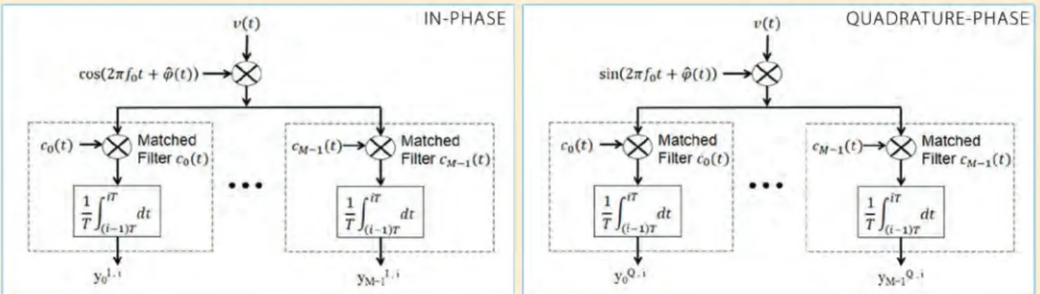
The principle of an orthogonal M-ary modulation demodulator consists, first, in applying a matched filter for each symbol of the alphabet and, sec-ond, in choosing the symbol identified by the largest matched filter output as the transmitted symbol. Therefore, the CSK demodulator consists of two banks of matched filters, one in in-phase and another in quadrature-phase for each possible PRN code shift (see Figure 5).
Assuming a perfect code delay syn-chronization, a perfect orthogonality between any two PRN code shifts, and that the symbol x was transmitted at instant i, the in-phase and quadrature-phase outputs of the kth matched filter at
instant , can be modeled as:
where is the carrier phase estima-tion, and are independent (due to PRN code shift orthogonality) narrow-band Gaussian noises with power equal to σ2 = (R
s · N0)/(2P), and Rs is the CSK
symbol rate (Rs = 1/Ts). From Equation (7), it can be observed that due to PRN code orthogonal properties, only the matched filter output of the transmitted symbol has a useful term, or , where-as the other matched filters outputs only contain noise.
Vector YI,i represents the in-phase
outputs of the matched filters and for a coherent demodulation process, vector
YI,i suffices to demodulate the data (J. G.
Proakis et alia) by choosing the symbol FIGURE 4 CSK(U, N) configuration example
identified by the largest matched filter output as the estimated symbol.
The sensitivity of the coherent demodulator to phase estima-tion errors, shown by Equaestima-tion (8), may be overcome thanks to a non-coherent demodulation using a new vector, with compo-nents (noiseless expression):
This non-coherent demodulation still requires good fre-quency Doppler estimation, with errors typically lower than
to constrain power losses below one decibel.
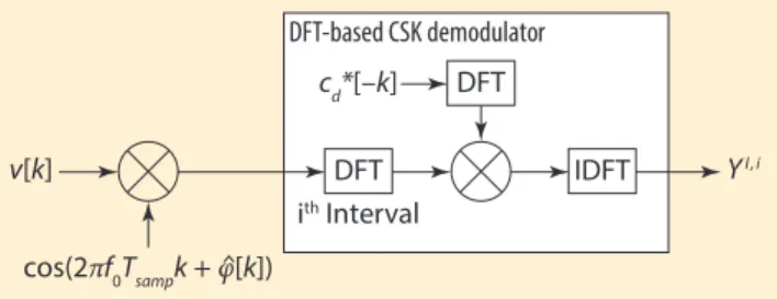
Finally, as each CSK symbol is a circular shift of the funda-mental PRN sequence, an efficient demodulator implementa-tion would rely on the computaimplementa-tion of the correlaimplementa-tion func-tion in the frequency domain using discrete Fourier transform (DFT) — or Fast Fourier transform (FFT) and inverse discrete Fourier transform (IDFT) or IFFT — because this type of demodulator conducts a smaller number of operations than a correlator-based demodulator(A. Garcia-Pena et alia, 2010).
Figure 6 shows the scheme of the DFT-based CSK demodulator in which the demodulator could be improved by replacing the DFT by an FFT. (v[k] represents the sampled received signal at the receiver RF block output.)
Considerations for a CSK Modulation
on a GNSS Receiver
Two of the major drawbacks of a CSK-modulated signal are the need for a pilot signal for synchronization purposes and the increase of the receiver complexity. In this section these issues are tackled through a comparison between the effects of CSK- and BPSK-modulated signals on a GNSS receiver. Except for the data-signaling scheme, the CSK and BPSK signals share similar properties and parameters:
• The total power of both signals is equally shared between a data and a pilot component.
• They have the same PRN chipping rate and the same pri-mary PRN code length, both on data and pilot components.
Impact on the Receiver Architecture. The demodulation pro-cess of a CSK-modulated signal is intuitively more complex than the demodulation process of a BPSK modulation, because it requires more correlators. We assess the increase in complex-ity here by means of the number of multiplications required for the demodulation of both CSK and BPSK signals.
Table 1 shows the number of multiplications required when demodulating one symbol for a CSK(U,1) (mapping U bits and spanning N=1 PRN code) and for a traditional BPSK demodu-lator when U bits are sequentially demodulated.
Two types of demodulators are proposed for the CSK signal: a bank of matched filters (or correlators) and an FFT-based correlator with the radix-2 Cooley-Tukey FFT algorithm (described in the article by P. Marti-Puig). Although the FFT-based demodulator moderately reduces the complexity of a bank of matched filters demodulator, its complexity remains significantly higher than the complexity of a typical BPSK demodulator.
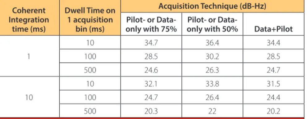
Effect on Signal Acquisition. Here we compare the joint data/ pilot acquisition method (not applicable to CSK) and the pilot-only acquisition method (applicable to both modulations) in order to inspect the degradation on the acquisition sensitivity introduced by a CSK modulation on the data component. Both methods have the same frequency and code delay uncertainty, and use the same acquisition detector: the standard single dwell acquisition technique described by E. Kaplan and C. Hegarty (see Additional Resources).
Table 2 and Table 3 show the acquisition threshold (total sig-nal C/N0) for the joint data/pilot acquisition method and for the pilot-only acquisition method with different data/pilot power share and for different PRN code lengths, respectively, 1,023 and 10,230 chips. The targeted false alarm probability equals the inverse of the PRN length (~ 10-3 and 10-4) and the targeted
detection probability is set to 90 percent. From these tables, we
conclude that the BPSK modulation seems more appropriate for acquisition purposes, as it enables the possibility of a joint data/pilot acquisition. However, if a 75–25 percent pilot/data power split is used, BPSK and CSK signals would have similar performances.
Effect on Signal Tracking. The benefits of a pilot component in GNSS signal code and phase tracking have been widely dem-onstrated and publicized since the early 2000s. As reflected in the discussion in the works by E. Kaplan and C. Hegarty, and O. Julien, when the pilot component’s power expressed relative to the composite data plus pilot signal’s power is 50 percent or more, one may expect that most receivers will only rely on the FIGURE 6 DFT-based CSK demodulator scheme
v[k] YI,i cd*[–k] cos(2πf0Tsampk + φ[k]) DFT IDFT DFT-based CSK demodulator ith Interval DFT Number of Multiplications CSK BPSK PRN Code
Length U Radix-2 Bank of Traditional Correlation Correlator
1023 6 11264 65472 6138 8 11264 261888 8184 10230 6 245760 654720 61380 8 245760 2618880 81840 10 245760 10475520 102300 12 245760 41902080 122760
Table 1 Number of multiplications required for demodulating U bits/symbols with a CSK(U,1) configuration and a BPSK configura-tion (from A. Garcia-Pena et alia, 2013)
pilot component for tracking in order to benefit from:
• larger coherent integration time on both code and carrier tracking (phase and/or frequency) and
• more robust and more linear dis-criminator or estimator for the carri-er tracking (phase and/or frequency). In this case the data component will be processed only for demodulation purposes.
A consequence of these assumptions is that we should expect the CSK imple-mentation on the data component to have limited effects on the receiver’s tracking performance as long as enough power is allocated to the pilot component.
Bit Error Corrections Schemes
Adapted to CSK Modulations
The robustness against errors of a digi-tal message defined by a sequence of information bits, is usually character-ized by the bit error rate (BER) and the associated metrics such as word, page, or
frame error rate. In the case of a
naviga-tion message containing the ephemeris and clock data necessary to compute the PVT solution, we also introduced
the CED error rate in order to define the robustness of message reception.
The error rate metric is a function of the Eb/N0, translating the ratio between the energy carried by an information bit and the noise power density. Rather than increasing the effective Eb/N0 by reducing the bit rate or by increasing the received power in order to improve the message reception’s robustness to errors, an efficient approach is to rely on error correction codes, also known as chan-nel codes.
The application of a channel code consists of introducing —in a controlled manner — redundant bits into the mes-sage. By exploiting this redundancy the receiver is able to correct some errors introduced by the channel. This chan-nel code decreases the demodulation threshold and increases the signal data availability.
Although the first civil GNSS signals, GPS and GLONASS C/A, do not imple-ment a channel code specifically dedi-cated to error correction, all modernized signals possess one. The most classical scheme relies on binary channel codes, of which the most well-known in the
GNSS field is the standard Consulta-tive Committee for Space Data Systems (CCSDS) convolutional code (7, ½), used in Galileo signals, as well as in GPS L2C, L5, and SBAS signals.
The newest GNSS signals are pro-tected by more powerful channel codes, such as the low density parity check (LDPC) used in the GPS III civil signal, L1C, or the Reed-Solomon (Non-binary or Q-ary) codes. Although common in satellite communications (e.g., Reed-Solomon is used for DVB-S channel code), these latter options are not often used currently in GNSS. We can cite as an example the QXSS LEX signal.
Note that the correction capacity of the channel code will also depend on the chosen decoding method within the receiver. Many pairs of encoding processes and decoding schemes may be proposed for a CSK signal. In this article, we identify several examples and describe them further in the following sections.
Two Examples of Encoding Schemes
Binary Channel Codes. In this case, the channel code implemented in the latest designed GNSS signal, the rate ½ LDPC channel code of the GPS L1C subframe 2, has been used with a CSK-modulated signal, in order to compare the CSK with the BPSK modulation results.
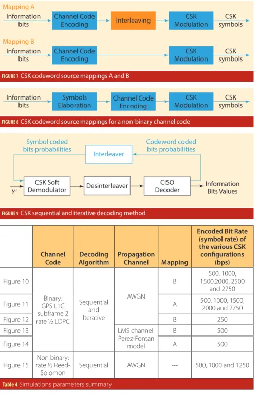
Following the encoding process, two different methods (presented schemati-cally in Figure 7) have been applied to sort and map the encoded bits into CSK symbols, referred to as mapping A or mapping B and defined in the papers by A. Garcia-Pena et alia, 2010 and 2013. Mapping B directly maps the encoded bits in their temporal order, and thus all the bits mapped by a CSK symbol belong to the same message. Mapping A con-sists of mixing the encoded bits through an interleaver and, as a result, each bit mapped by a CSK symbol is forced to belong to a different message.
Non-Binary Channel Codes. In a Q-ary channel code, each channel code sym-bol maps a determined set of Q bits. Therefore, the typical design of a Q-ary channel code on a CSK signal consists of having the same size (or number of bits) for a Q-ary symbol as for a CSK symbol
Coherent Integration time (ms) Dwell Time on 1 acquisition bin (ms) Acquisition Technique (dB-Hz) Pilot- or
Data-only with 75% only with 50%Pilot- or Data- Data+Pilot 1 10 34.7 36.4 34.4 100 28.5 30.2 28.5 500 24.6 26.3 24.7 10 10 32.1 33.8 31.5 100 24.7 26.4 24.4 500 20.3 22 20.2
Table 2 Example of expected acquisition thresholds (Total Data+Pilot C/N0 of the Signal) for PRN length of 1023 chips (from A. Garcia-Pena et alia, 2013)
Coherent Integration time (ms) Dwell Time on 1 acquisition bin (ms) Acquisition Technique (dB-Hz) Pilot- or
Data-only with 75% only with 50%Pilot- or Data- Data+Pilot 1 10 35.3 37 35.2 100 29.2 30.9 29.1 500 25.2 26.9 25.3 10 10 33.1 34.8 32.4 100 25.5 27.2 25.2 500 20.9 22.7 20.9
Table 3 Example of expected acquisition thresholds (Total Data+Pilot C/N0 of the Signal) for PRN length of 10230 chips(A. Garcia-Pena et alia, 2013)
(U = Q). In doing so, each Q-ary symbol may be directly transmitted by one CSK symbol since they represent the same set of Q bits (see Figure 8).
In this case, the family of channel codes implemented in the QZSS-LEX signal, primitive Reed-Solomon chan-nel codes, has been used with a CSK signal. But in order to be able to provide a straight forward comparison between binary (rate ½ LDPC) and non-binary channel codes schemes, the Reed-Sol-omon code rate has been forced to ½
(which is different from the QZSS LEX Reed-Solomon rate).
Two Examples of Decoding Schemes. At receiver level, the decoding algorithms may be sorted into two main groups: sequential decoding algorithms (direct classical technique) or iterative decoding algorithms as shown in Figure 9: • Sequential algorithm: the decoder’s
outputs are considered to be the information bits estimated by the receiver, and as such, are sent to any downstream processing block (for
example, CRC). It is easy to apply, and requires limited memory (A. Garcia-Pena et alia, 2013).
• Iterative algorithm, for example the bit-interleaved coded modulation with iterative decoding (BICM-ID) (described in G. Caire et alia): the output of the decoder is fed back into the demodulator/decoder to refine the bit estimation. This feedback may be repeated several times before the decoder decides to output the final information bits. The performance, along with the processing power and memory required, increase with the number of iterations.
In case an interleaver is applied at the emitter level, the receiver must implement a disinterleaver for both the sequential and iterative algorithms, and also the associated interleaver for the iterative algorithm (see Figure 9).
Examples of Demodulation
Performance of Correction
Schemes
This section presents the results of some demodulation performance sim-ulations, comparing the bit error rate (BER) versus the carrier-to-noise-den-sity (C/N0) for various CSK configura-tions, in the presence of average white Gaussian noise (AWGN) or LMS (land mobile satellite, urban environment) propagation channels.
The following assumptions are made in every analyzed case:
• The primary PRN code duration is Ts = 4 milliseconds, which yields a bit rate of 250 encoded bits per second, for a BPSK modulation where one PRN code spans one encoded bit or BPSK symbol.
• The C/N0 provided in all the figures refers to the data component C/N0 only.
• For both propagation channels (AWGN, LMS), perfect code delay and carrier frequency estimation are assumed, as well as a perfect frame or page synchronization and the noise power is assumed to be perfectly known.
• For simulations in an AWGN chan-nel, a coherent demodulation is con-ducted and a perfect carrier phase FIGURE 7 CSK codeword source mappings A and B
Mapping A
Information
bits Channel CodeEncoding Interleaving ModulationCSK symbolsCSK
Mapping B
Information
bits Channel CodeEncoding ModulationCSK symbolsCSK
FIGURE 8 CSK codeword source mappings for a non-binary channel code
Information
bits ElaborationSymbols Channel CodeEncoding symbolsCSK
CSK Modulation
FIGURE 9 CSK sequential and iterative decoding method
Yi
CSK Soft
Demodulator Desinterleaver DecoderCISO
Interleaver Symbol coded
bits probabilities Codeword codedbits probabilities
Information Bits Values
Channel
Code AlgorithmDecoding Propagation Channel Mapping
Encoded Bit Rate (symbol rate) of the various CSK configurations (bps) Figure 10 Binary: GPS L1C subframe 2 rate ½ LDPC Sequential and Iterative AWGN B 1500,2000, 2500 500, 1000, and 2750 Figure 11 A 500, 1000, 1500, 2000 and 2750 Figure 12 B 250 Figure 13 LMS channel: Perez-Fontan model B 500 Figure 14 A 500
Figure 15 rate ½ Reed-Non binary:
Solomon Sequential AWGN --- 500, 1000 and 1250
estimations is assumed.
• For simulations in a LMS channel, a non-coherent demodu-lation is conducted and the channel attenuation impact a(t) is assumed to be perfectly known.
• The chosen LDPC decoding method to be implemented in the SISO decoder (see Figure 9) is the classical message-pass-ing or propagation-belief algorithm (see F. R. Kschischang
et alia).
• The chosen Reed-Solomon decoding method to be imple-mented in the decoder block (Figure 9) is the Berlekamp/ Forney algorithm (described in the article by S. Lin et alia). Note that the bit rate presented in Table 4 corresponds to the bit rate of the coded bits (sometimes also referred to as symbols). In order to obtain the useful information bit rate, Table IV rates must be multiplied by the channel code rate, equal to ½.
Binary Channel Code Correction Schemes in AWGN
Channel
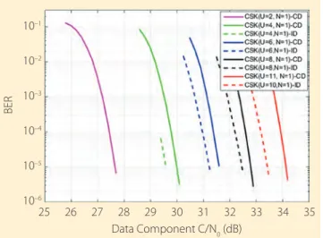
Figure 10 and Figure 11 show the C/N0 required to obtain a given BER (usually a value of 10-5 is targeted) when the bit rate is increased by a factor of U with respect to BPSK-modulated signal with one symbol or encoded bit = one PRN code (250 sps for Ts = 4 ms). From those two figures, we can see that map-ping A outperforms mapmap-ping B and that iterative decoding also outperforms classical decoding.
Figure 12 shows various CSK configurations, all providing the same encoded bit rate of 250 bps. These configurations are benchmarked to a 250 bps BPSK modulation with LDPC encoding (information bit rate of 125 bps). Mapping B con-figurations are the only ones selected, because they generate messages with a time duration (or latency) equal to the bench-marked BPSK signal and thus yield a fair comparison between the different options.
From Figure 12, we observed that the demodulation perfor-mance improves when more bits are mapped on a CSK symbol. However, this also implies potential limitations, as the CSK symbol must be longer to obtain the same bit rate. Moreover,
this improvement seems to reach a saturation point when a certain number of bits mapped by a CSK symbol is attained.
Finally, current CSK configurations with GPS L1C subframe 2 rate ½ LDPC channel code, mapping B, and the same message time duration (or latency) are still outperformed by a classi-cal BPSK-modulated signal. As the selected LDPC was spe-cially designed to be implemented in a BPSK modulation and not in a CSK modulation, it is expected that this degradation could be mitigated (and the effect even inversed) by specifically designing channel codes adapted to CSK, as investigated by M. Aubault-Roudier et alia.
Binary Channel Code Correction Schemes in an Urban
Environment for a Non-Coherent Demodulation
Process
The simulated urban environment represents an LMS channel, based on the Perez-Fontan channel mathematical model. This channel model characterizes the c(t) values with a Loo distribu-tion, as described in the articles by F. Perez-Fontan et alia) and (R. Prieto-Cerdeira et alia) and is assumed to be non-frequency FIGURE 10 BER vs C/N0 of a CSK signal using the “mapping B” encoding
process in an AWGN channel
10–1 10–2 10–3 10–4 10–5 10–6 BER Data Component C/N0 (dB) 25 26 27 28 29 30 31 32 33 34 35
FIGURE 11 BER vs C/N0 of a CSK signal using the “mapping A” encoding process in an AWGN channel
10–1 10–2 10–3 10–4 10–5 10–6 BER Data Component C/N0 (dB) 26 27 28 29 30 31 32 33 34
FIGURE 12 BER vs C/N0 of different CSK configurations with “mapping B” having the same bit rate in an AWGN channel
10–1 10–2 10–3 10–4 10–5 10–6 BER Data Component C/N0 (dB) 22 22.5 23 23.5 24 24.5
selective, and thus the received signal can be modeled as pre-sented in Equation (5).
Only the “intermediate shadowing” state of the Perez-Fontan model is simulated with the following loop parameter values, α = –8dB, Ψ = 4.5dB, MP = -19,2dB, because this state is representative of moderate-to-difficult reception conditions. The user speed is set to 50 km/h and the satellite elevation angle to 40 degrees. We have used the non-coherent demodulation process described in the paper by A. Garcia-Pena et alia (2014)).
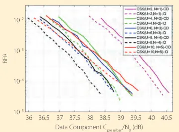
Cpre_urban/N0 is defined as the useful signal power at the corre-lator output when the propagation channel impact is not taken into account (except for space free losses). Figure 13 and Figure 14 show the BER as a function of the data component Cpre_urban/ N0 of a CSK signal with a bit rate increase equal to two with respect to the BPSK signal (with one symbol = one PRN code) when conducting a non-coherent demodulation.
From Figure 13 and Figure 14, one can observe that the com-bination of a CSK signal and a non-coherent demodulation pro-cess eases transmission of information through environments
with moderate/difficult reception conditions. An important outcome of those results is that the best demodulation per-formances are no longer obtained by CSK configurations that map a lot of bits per symbol (A. Garcia-Pena et alia, 2010a). Long CSK symbol duration appears to be detrimental in urban environments (Figure 13 with “mapping B”).
Q-ary Channel Code Correction Scheme
in AWGN Channel
We also performed a simulation of a CSK signal encoded by the non-binary rate ½ Reed-Solomon channel code and tested in an AWGN propagation channel. Figure 15 presents the results of the BER versus the data component C/N0 for different CSK configurations CSK(U,1).
Figure 15 indicates that, for a CSK modulation, a Reed-Solomon channel code with a low number of bits mapped by a Q-ary (or CSK) symbol is suboptimal. In fact, when compared to binary channel code correction schemes, it appears that at least eight bits should be mapped in order to obtain the full potential of the Reed-Solomon scheme, although in such cases, the message duration becomes large.
Conclusions
This article has presented the CSK modulation principle, high-lighting some of its specific features related to demodulation performance.
We identified various correction schemes for CSK, using either binary channel code (binary LDPC) with classical or iterative decoding, or Q-ary channel code (Reed-Solomon). The results show that CSK is very sensitive to appropriate channel code design. However, this analysis still needs further refine-ment, as the binary channel code tested in this article is the GPS L1C subframe 2 LDPC code, which was specially designed for a BPSK modulation and not for a CSK modulation.
Over AWGN propagation channels, the results contributed to confirmation of the expected behavior of the CSK encod-ing as an M-ary signalencod-ing technology. CSK provides interest-FIGURE 13 Bit error rate versus carrier-to-noise-density ratio of a CSK
signal using the “mapping B” encoding process with twice the BPSK signal bit rate in an LMS channel
10–2
10–3
10–4
10–5
BER
Data Component Cpre urban/N0 (dB)
36 36.5 37 37.5 38 38.5 39 39.5 40 40.5
FIGURE 14 Bit error rate versus carrier-to-noise-density ratio of a CSK signal using the “mapping A” encoding process with twice the BPSK signal bit rate in an LMS channel
10–2
10–3
10–4
10–5
BER
Data Component Cpre urban/N0 (dB)
34.5 35 35.5 36 36.5 37 37.5 38 38.5 39 39.5
FIGURE 15 Bit error rate versus carrier-to-noise-density ratio of a CSK signal with a Reed-Solomon channel code with r=1/2 in an AWGN channel BER Data Component C/N0 (dB) 30 30.5 31 31.5 32 32.5 33 33.5 10–1 10–2 10–3 10–4 10–5 10–6
ing demodulation properties but does not outperform BPSK implementation with equivalent bit rates and with the same message time duration or latency (at least for the cases presented in this study).
Over LMS propagation channels, the results obtained thus far are encourag-ing. We would expect that, thanks to appropriate channel encoding, equaliza-tion, and non-coherent Rake-like receiv-er implementation, the CSK modulation could improve data availability in urban canyons.
Nevertheless, in comparison with a BPSK modulation, CSK modulation also has some drawbacks:
• First, the complexity of the receiver is significantly increased. Although efficient CSK-demodulation schemes in the frequency domain would mod-erately reduce the complexity, they remain generally more complex than the traditional BPSK demodulator. • Second, the signal synchronization
can no longer be conducted over the data component, and thus a pilot component is mandatory. As most modernized GNSS signals already rely on a pilot component, this draw-back has limited impact, except per-haps on acquisition sensitivity. All of this motivates additional work on CSK. Ongoing work aims at the optimization of the encoding-decoding
scheme, combined with appropriate channel equalization, non-coherent demodulation, and Rake-like receiv-er architecture, with the objective of achieving optimal performance in urban environments and finalizing our under-standing and assessment of CSK’s pros and cons. Further results are expected in the upcoming months, which should provide opportunities to consolidate the lessons learned about the CSK potential for GNSS signals.
Additional Resources
[1] Caire, G., and G. Taricco, and E. Biglieri, “Bit-Interleaved Coded Modulation,” Proceedings of
the IEEE International Symposium on Information Theory, 29 June - 4 July 1997
[2] Dillard, G. M, and M. Reuter, J. Zeiddler, and B. Zeidler, “Cyclic Code Shift Keying: A Low Prob-ability of Intercept Communication Technique,”
IEEE Transactions on Aerospace and Electronic Systems, Vol. 39, No 3, July 2003
[3] Garcia-Pena, A. (2014), and P. Paimblanc, O. Julien, L. Ries, and T. Grelier, “Analysis of Different CSK Configurations in an Urban Environment When Using Non-coherent Demodulation,” 7th
ESA Workshop on Satellite Navigation Technolo-gies and European Workshop on GNSS Signals and Signal Processing (NAVITEC), December
3–5, 2014
[4] Garcia-Pena, A. (2010), and M-L. Boucheret, C. Macabiau, J-L. Damidaux, L. Ries, Stéphane Corazza, and A-C. Escher, “Implementation of Code Shift Keying Signalling Technique in GALILEO E1 Signal,” 5th ESA Workshop on Satellite
Navigation Technologies and European Workshop on GNSS Signals and Signal Processing (NAVITEC),
December 8–10, 2010
[5] Garcia-Pena, A. (2013), and D. Salos, O. Julien, L. Ries, and T. Grelier, “Analysis of the Use of CSK for Future GNSS Signals,” Proceedings ION GNSS
2013+, Nashville Tennessee USA, September
16–20, 2013
[6] Japan Aerospace Exploration Agency,
Inter-face Specification for QZSS (IS-QZSS) Draft V1.6,
November 28, 2014
[7] Julien, O., Design of Galileo L1F Receiver
Track-ing Loops, Ph.D. Thesis, Department of
Geomat-ics Engineering, University of Calgary, Canada, July 2005
[8]Kaplan, E. and Hegarty, C., Understanding
GPS: Principles And Applications, Artech House,
2005
[9] Kschischang, F. R., and B. Frey, and H.-A. Loeli-ger,, “Factor Graphs and the Sum-Product Algo-rithm,” IEEE Transactions on Information Theory, Vol 47, Issue 2, pages 498-519, February 2001
[10] Lin, S. and D.J. Costello, Error Control Coding:
Fundamentals and Applications, second edition,
Pearson – Prentice Hall, 2004
[11] Marti-Puig, P., “Two Families of Radix-2 FFT Algorithms With Ordered Input and Output
Data,” IEEE Signal Processing Letters, Vol. 16, Issue 2, pages 65–68, February 2009
[12]Perez-Fontan, F., and M. A. Vázquez-Cas-tro, S. Buonomo, J. P. Poiares-Baptista, and B. Arbesser-Rastburg, B, , “S-Band LMS Propagation Channel Behaviour for Different Environments, Degrees of Shadowing, and Elevation Angles,
IEEE Transactions on Broadcasting, Vol. 44, No. 1,
March 1998
[13] Prieto-Cerdeira, R., and F. Schubert, R. Orus-Perez, J.A. Garcia-Molina, and F. Zanier, ”Flexible Statistical Multipath and Shadowing Model for Software and Hardware Simulations, Proceedings
ION GNSS+ 2011, Portland, Oregon, USA 2011
[14] Proakis, J. G. and Salehi, M., Digital
Commu-nications, 5th ed, McGraw-Hill, 2008
[15] Roudier, M., and A. Garcia-Pena, O. Julien, T. Grelier, L. Ries, C. Poulliat, M-L. Boucheret, and D. Kubrak, “Demodulation Performance Assess-ment of New GNSS Signals in Urban Environ-ments,” Proceedings ION GNSS+ 2014, Tampa, Florida USA September 8–12, 2014
[16] Wong, A. Y.-C. and V. C. M. Leung, V. C. M., “Code-Phase-Shift Keying: A Power and Band-width Efficient Spread Spectrum Signaling Tech-nique for Wireless Local Area Network Applica-tions,” IEEE Canadian Conference on Electrical and
Computer Engineering, 1997
Authors
Axel Garcia-Peña is a researcher/lecturer with the SIGnal processing and NAV-igation (SIGNAV) research group of the TELECOM lab of École Nationale de l’Aviation Civile (ENAC, French Civil Aviation University), Toulouse, France. He received his double engineer degree in digital communications from SUPAERO and UPC, and his Ph.D. from the Department of Mathematics, Computer Science and Telecom-munications of the INPT (Polytechnic National Institute of Toulouse), France.His research inter-ests are GNSS navigation message demodula-tion, optimization and design, GNSS receiver design, and GNSS satellite payload.
Marion Aubault-Roudier
is a radionavigation engi-neer in the navigation/loca-tion signals department in CNES, the French Space Agency, where she is involved in the optimiza-tion of GNSS signals as wells as the assessment of GNSS user segments (receivers, algorithms). Roudier graduated as an electronics engineer from ENAC (Ecole Nationale de l’Aviation Civile) in Toulouse, France. She received her Ph.D. from the Department of Mathematics, Computer Sci-ence and Telecommunications of the INPT (Poly-technic National Institute of Toulouse), France.
Results show that CSK is
very sensitive
to appropriate
channel code design. However, this analysis still
needs
further refinement...
Marie-Laure Boucheret
received the electrical engi-neering degree from ENST Bretagne and a Ph.D. degree in communications from TELECOM ParisTech. She has been a successful research engineer at the French Philips Research Laboratory (1985¬–1986), engineer at Thales Alenia Space in telecommunication and trans-mission (1986–1991), associated professor then a Professor at TELECOM ParisTech (1991–2005). Since 2005, Boucheret has been a Professor at the National Polytechnic Institute of Toulouse (ENSEEIHT - University of Toulouse). She is also with the Signal and Communication group of the IRIT Laboratory. Her main research interests include design of modulation and coding schemes for satellite communications, and algo-rithms and architecture of digital receivers.
Charly Poulliat received an electrical engineering degree from ENSEA, Cergy-Pontoise, France, an M.Sc. degree in signal and image processing from the Uni-versity of Cergy-Pontoise and his Ph.D. degree in signal processing for digital communications from the University of
Cergy-Pontoise. Since 2011, Poulliat has been a professor with the National Polytechnic Institute of Toulouse (ENSEEIHT - University of Toulouse). He has been the head of the Signal and Com-munications Group of the IRIT Laboratory since 2013. His main research interests include: signal processing for digital communications (satellite and terrestrial), analysis, design and optimiza-tion of iterative receivers, andchannel coding (LDPC codes, turbo codes) and related iterative decoders.
Olivier Julien is the head of the SIGnal processing and NAVigation (SIGNAV ) research group of the TELE-COM lab of ENAC (Ecole Nationale de l’Aviation Civi-le), Toulouse, France. He graduated as an electrical engineer from the ENAC and received his Ph.D. from the Department of Geomatics Engineering at the University of Calgary, Canada. Julien’s research interests are GNSS receiver design, GNSS multipath and inter-ference mitigation, and GNSS interoperability.
Lionel Ries is head of the navigation/location signals department in CNES, the French Space Agency. The department activities cover signal design and processing, receivers and payloads regarding location and navigation systems
including GNSS (Galileo, GNSS space receivers), Search & Rescue by satellite (SARSAT, MEOSAR), and Argos (Advanced Data Collection and Location by Satellite, mostly for environ-ment and wildlife monitor-ing). He also coordinates CNES research activities for future location/navigation signals, user segments equipment, and pay-loads.