HAL Id: hal-01226406
https://hal.archives-ouvertes.fr/hal-01226406
Submitted on 15 Nov 2017
HAL is a multi-disciplinary open access archive for the deposit and dissemination of sci-entific research documents, whether they are pub-lished or not. The documents may come from teaching and research institutions in France or abroad, or from public or private research centers.
L’archive ouverte pluridisciplinaire HAL, est destinée au dépôt et à la diffusion de documents scientifiques de niveau recherche, publiés ou non, émanant des établissements d’enseignement et de recherche français ou étrangers, des laboratoires publics ou privés.
A MIMO LPV control of semi-active suspension
Manh Quan Nguyen, Olivier Sename, Luc Dugard
To cite this version:
Manh Quan Nguyen, Olivier Sename, Luc Dugard. A MIMO LPV control of semi-active suspension. VSDIA 2014 - 14th Mini Conference on Vehicle System Dynamics, Identification and Anomalies, Nov 2014, Budapest, Hungary. pp.415 - 425. �hal-01226406�
A MIMO LPV CONTROL OF SEMI-ACTIVE SUSPENSION
M.Q. Nguyen, O. Sename and L. DugardUniv. Grenoble Alpes, GIPSA-lab, F-38000 Grenoble, France CNRS, GIPSA-lab, F-38000 Grenoble, France (e-mail: {manh-quan.nguyen,
olivier.sename, luc.dugard}@gipsa-lab.grenoble-inp.fr)
Received: November 10, 2014
ABSTRACT
In this paper, we present a new Linear Parameter Varying LPV/H∞ motion adaptive suspension controller that takes into account the three main motions of the vehicle vertical dynamics: bounce, roll and pitch motions that affect the passengers’ comfort. The new approach aims, by using a detection of the vehicle motions, at designing a controller which is able to adapt the suspension forces in the four corners of the vehicle according to the dynamical motions, in order to mitigate the road-induced vibrations. The main idea of this strategy is to use three scheduling parameters, representative of the motion distribution in the car dynamics, to adapt and distribute efficiently the suspension actuators. The motion detection strategy is following two possible methods: a motion mode energy method (obtained from the literature) and a load transfer distribution one. A full 7 degree of freedom (DOF) vertical model is used to describe the body motion (chassis and wheels), and to synthesize the LPV controller. The controller solution is derived in the framework of the LPV/H∞ and based on the LMI solution for polytopic systems. Some simulation results will demonstrate the effectiveness of this approach.
Keywords: Vehicle dynamics, LPV/H∞ control, suspension control, motion detection, motion mode energy, load transfer distribution
1. INTRODUCTION
The vehicle is an extremely complex system which consists of multi-subsystems in order to enhance the driving comfort, stability and safety thanks to either passive solution (seat belt...) or active solutions using various actuators (ESC- electronic stability control, ABS- anti-lock braking system, controlled suspensions...). Together with many recent breakthroughs in the automotive industry, many studies have been fulfilled on either the suspension control aspects or the steering-braking control strategies, or a combination of them. (e.g. see [1], [2])
Furthermore, the suspension systems play a key role in vehicle dynamics. Indeed, a well designed suspension system may considerably improve not only the passenger comfort but also the car road holding. Several control design problems for suspension systems have then been tackled with many approaches during the last decades. In [3], the authors presented several control strategies for semi-active suspensions (based on the Skyhook, Groundhook, ADD, and LPV approach). Some other works concerning quarter car model have dealt with optimal control in [4], adaptive control in [5] or robust linear control in [6]. Suspension control problems have also been resolved using a half car model as in [7] using an optimal control, [8] using multi-objective control and [9] using decoupling strategies. Finally a full car vertical model has been considered to handle simultaneously the bounce, pitch and roll motions, as in [10]
using a mixed H2/H∞ multi-objective control, and in [11] developing H∞ controllers for two decoupled vehicle heave-pitch and roll-warp subsystems.
On the other hand, the vehicle motions depend considerably on the road conditions, and it is well recognized that the vehicle dynamics (in terms of comfort and road holding) will benefit from the online adaptation of the suspension performances. Some studies have been developed to adapt the suspension actuators according to the road environments (see [12] and [13]). Recently, in [14] a motion mode energy method is developed and used in [15] to propose a switched control to handle the bounce, roll and pitch motions. While, in this paper, the motion detection strategy is used (together with a load transfer distribution one), another control approach is proposed to avoid the abrupt changes due to switching, to ensure global stability of the closed-loop system and to simplify the control implementation step.
The main contribution of this paper is to propose a Multi-Input Multi-Output (MIMO) LPV controller to enhance the car vertical dynamics using suspension actuators only. Since the passengers’ comfort is mainly handled in this work, the objective is to improve the road induced vibration insulation on the bounce, roll and pitch motions. The MIMO suspension control strategy is designed in the LPV framwork in order to allow for real time performance adaptation according to the vehicle dynamics. Moreover, thanks to LPV/H∞ framework, the suspension controller ensures the stability and performances of the closed system for all parameter variations. Additionally, by using a suitable strategy of varying parameters, the controller admits a smooth transition from a motion-mode to others. Finally, the authors wish to emphasize the advantages of using only one suspension controller that is compatible with the controllers of the other sub-systems (such as steering and braking systems).
The paper is outlined as follows. Section II is devoted to the brief description of the full vehicle model used for synthesis and validation. Section III presents two methods allowing to detect the different motions of vehicle. Section IV describes the design of a LPV/H∞ suspension controller that will adapt to the three motions of chassis. In section V, the results of the proposed method are presented with some time domain simulations. Finally, some conclusions are given in the last section.
Throughout the paper, the following notations will be adopted: subscripts i= (f,r) and j= (l,r) are used to identify the vehicle front, rear and left, right positions respectively. The subscripts (s,t) stand for the forces provided by suspensions and tires, respectively. The index (x, y, z) denotes forces or dynamics in the longitudinal, lateral and vertical axes, respectively. zdefij holds for the suspension deflection at each corner of the vehicle. m = ms + musf l + musf r + musr l + musrr is the total vehicle mass.
2. VEHICLE MODELLING
In this work, a full car vertical model is used for the analysis and control of the vehicle dynamic behaviors. This is a 7 degrees of freedom (DOF) suspension model which is obtained from the nonlinear full vehicle model (referred in [2],[16], [17]). The corresponding parameters can be found in the table [I]. It involves modeling not only of the chassis dynamics: vertical (zs), roll (θ ) and pitch (φ ), but also figuring out
the vertical displacements of the wheels (zusij ). The dynamic equation of the 7 DOF vertical model is given as follow:
where Ix (resp. Iy) is the moment of inertia of sprung mass around the longitudinal (resp. lateral) axis, h: the height of center of gravity (COG), zs the vertical displacement of COG, θ the roll angle of the sprung mass, φ the pitch angle of the sprung mass, and zusij the vertical displacements of wheels. Ftzij are the vertical tire forces, given as:
where ktij : the stiffness coefficient of the tires.
Suspension model: The vertical suspension forces Fsij at 4 corners are modeled by a spring and a damper (see [18]) with non linear characteristics for simulation and linear ones for control design. The equation below allows to model the suspension force used in control design:
where kij: the nominal stiffness coefficient spring, cij: the nominal damping coefficient and uij H∞ : the suspension control (uij H∞ = 0 holds for passive suspension). zsij : are the deflection positions for the four suspensions and are given by:
Assuming that the roll and pitch angles are small enough and denoting xm = [zs θ φ]T and xs = [zsfl zsfr zsrl zsrr]T ,the linear approximation of (4) gives us:
By substituting the tire force equation (2) and the suspension force equation (3) to the dynamic vehicle equation (1) and assuming that, the chassis body is rigid, the characteristics of spring and damping are linear, and the displacement around the steady point is small enough, the linear model is given by: (see [19], [20] and [15] for more details).
where xu = [zusf l zusfr zusrl zusrr]T : the vertical displacement of each wheel.
Denoting z = [xmT xuT ]T and replacing equation (5) into equation (6), leads to:
(1) (2) (3) (4) (5) (6)
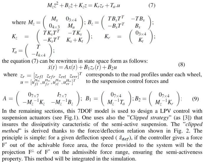
the equation (7) can be rewritten in state space form as follows:
where corresponds to the road profiles under each wheel, to the suspension control forces and
In the remaining sections, this 7DOF model is used to design a LPV control with suspension actuators (see Fig.1). One uses also the ”Clipped strategy” (as [3]) that insures the dissipativity caracteristic of the semi-active suspension. The ”clipped
method” is derived thanks to the force/deflection relation shown in Fig. 2. The
principle is simple: for a given deflection speed ( ), if the controller gives a force F* out of the achivable force area, the force provided to the system will be the
projection F⊥ of F* on the admissible force range, ensuring the semi-activeness
property. This method will be integrated in the simulation.
Fig 1: Suspension control plant using motion detection Fig 2: Clipped approach
3. MOTION VEHICLE DETECTION
The study of vehicle dynamics is a complex field since it requires to account for translation modes (lateral, longitudinal, vertical) and rotation ones (roll, pitch, yaw). As emphasized in many works, there is a strong coupling between these motions, even if the vehicle dynamics are often decomposed to solve some local problems (braking control, steering control...). This paper is concerned with the improvement of the vertical dynamics that include the vertical motion, the pitch and roll rotations. More particularly, as considered in previous studies ([15],[10],[11],[21]...) the objective is to develop a suspension control strategy that aims at reducing the effect of the road
(8)
induced vibrations, and then to enhance the passengers’ comfort. Note that the road holding objective could be considered as well since the 7 DOF model accounts for the wheel position dynamics (this will be the scope of future works). Moreover, as stated in the introduction, the vibration insulation for the vertical, roll and pitch motions will be based on a motion detection strategy. Such a detection can be based on the motion mode energy method proposed in [15], or on an estimation of the several load transfers.
3.1 Motion mode energy method
This approach (see [15], [14]), is briefly presented here. The mode energy method is based on calculating the energy contribution of each vibration mode to the entire vehicle vibration. A mode energy level of one motion is the energy dedicated to a mode and calculated by the sum of the system potential energy and kinetic energy in one mode. To carry out this work, the system state signal must be known. In fact, the state space vector consists of the bounce zs, roll θ , pitch φ and the displacements of the wheels zuij , and the corresponding derivatives. Therefore, five position sensors are used to measure the displacements of the chassis and the four wheels. Two gyrometer sensors are needed for roll and pitch angles.
Fig. 3. Motion detection using motion energy method
From the state space matrix A14x14 in equation (8), we calculate the eigenvalue matrix
Ω = diag[Λ Λ∗] and the eigen-vector matrix:
where Λ = diag [λ1, λ2,..., λ7] and Ψ = diag [ψ1, ψ1,..., ψ7], with λi,ψi, i = 1,2…7 are the eigenvalues and their corresponding eigenvectors of the state matrix A.
A modal matrix is then formed to change the reference frame from the physical coordinates (with coupled equations of motions) to principal coordinates (with uncoupled equation of motions) as follow:
Γ = [Ψ ΨΛ]Τ (10)
The measured system state vector can then be rewritten as a superposition of the motion-modes thanks to the modal matrix G as:
x(t) = Γq(t) (11)
where q(t): the modal amplitude vector in principal coordinate frame q = [q1 q2…q7]T and q(t) = pinv(Γ)x(t).
Let consider the ith motion mode q
i(t), the projection of qi into the physical coordinates is given by [di(t) i(t)], i = 1,2…7, where di(t) = real(ψiqi(t)), i(t)= real(φiλiqi(t)). Moreover di(t) can be expressed as [dqi(t) dui(t)] where dqi refers to body vibrations and
dui refers to wheel ones. Now this modal analysis is used to calculate the energy level for each vibration mode. The kinetic energy eki and potential energy epi stored in the ith
mode are derived, the sum of which, gives the energy level ei for the ith vibration
where Mm = diag[ms; Ix; Iy;musfl ;musfr ;musrl ;musrr ] and
H = diag[ksfl ;ksfr ;ksrl ;ksrr ;ktfl ;ktfr ;ktrl ;ktrr ].
ri is the projection of the road excitation input zri in the ith motion-mode in the same coordinate frame with the vehicle motion-mode. As mentioned before, we focus only on the body motion modes (bounce, roll and pitch). So the energy for these motions and the contribution ratio of each motion mode to the vehicle vibration are calculated only. Now, the energy contribution ratios ρ1,ρ2,ρ3 of the ith mode (i=1,2,3 correspond to bounce, roll and pitch respectively) are defined by:
where E(t) = e1(t)+e2(t)+e3(t). Of course,
It is worth noting that these ratios will be used as scheduling parameters to adapt the suspension control in order to improve the vibration insulation. Indeed, obviously,
ρ1,ρ2,ρ3 ≠ [0 1], when ρi = 0, it means that there are no energy contribution of ith motion-mode, conversely, ρi ≠ 0, ith vibration mode is detected.
3.2 Based on load transfer distribution vehicle dynamics
This method consists in a load transfer distribution strategy which allows to provide varying parameters that tune the suspension behaviors at the four corners, as represented in Fig. 4:
Fig. 4. Motion detection using load transfer
Roll monitoring by lateral load transfer (ρ2): The main idea is based on the evaluation the lateral load transfer when the vehicle is running (see [22]). Once there exists a load transfer from the left to the right vehicle side or vice-versa, it means that the vehicle is faced with roll vibration. Computing the right and left vertical forces allows to define:
where Fzl and Fzr are the vertical forces, ay is the lateral acceleration. Note that ρ2 ∈ [0 1]. When ρ2 = 0, there are no lateral load transfer, no roll motion. Conversely, if
ρ2≠ 0, the vehicle is in the roll motion.
Pitch monitoring by longitudinal load transfer(ρ3): Using the same principle as previously , the longitudinal load transfer (see [24]) is defined during the cruise. A
dynamic load distribution that can transfer load between the front and rear wheels as the vehicle accelerates or brakes will typically excite a pitch vibration. The pitch monitor is then defined as:
where the front and rear normal forces are given as:
where ax is the longitudinal acceleration. Note that ρ3 ∈ [0 1]. In reality, when the vehicle is accelerating the load is transferred to the rear wheels, and during the braking it is transferred to the front wheels. The longitudinal load transfer distribution is handled as: Whilst ρ3 = 0, there are no longitudinal load transfer, no pitch motion.
Conversely when ρ3 ≠ 0, we detect the pitch motion.
Bounce monitoring (ρ1):
Thanks to two load transfer distribution monitoring system for roll and pitch motion, we will use an another scheduling parameter ρ1 to monitor the bounce motion. This parameter is chosen as:
By this way, ρ1 ∈ [0 1], when ρ1 ≠0, the vertical motion (zs) should be taken into
account.
Remark: In this load transfer distribution method, we need only two accelerometers
to measure the lateral and longitudinal accelerations, one gyrometer sensor to measure the pitch angle. Thus, it is easier than the last method to implement in real time system.
4. A MIMO LPV/H∞ SUSPENSION CONTROLLER
In this section, a MIMO LPV suspension control is proposed thanks to the motion mode energy strategy, to mitigate the road induced effects. This controller is designed in the H∞ framework, which allows, using parameter dependent weighting functions, to get real-time adaptive performances.
4.1. Suspension control structure model
The controller is tuned thanks to the LPV/ H∞ strategy using a full 7 dof vertical model. The generalized plant is taken into account in the Fig.5 and includes the parameterized weighting functions. As discussed previously, we used the three varying parameters to schedule the weighting functions for the control objectives. These filters are selected as follows:
• Wzs (ρ1)= ρ1 1 ) 2 /( 3 1 + f
s π is shaped to reduce bounce amplification of the sprung mass between [0;10] Hz • Wθ (ρ2)= ρ2 1 ) 2 /( 2 2 + f
• Wφ (ρ3)= ρ3 1 ) 2 /( 2 3 + f
s π reduces the pitch motion in low frequency.
The authors stress that the interest of parameter dependant weighting functions is to allow for performance adaptation to the behavior of the vehicle dynamic. Indeed, the suspension actuators will be tuned according to the varying parameters in order to meet the desired performance. For example, as far as the bounce motion is concerned, when the scheduling parameter ρ1→1, the gain of the weighting function Wzs (ρ1) is large, and therefore the bounce motion will be penalized. In the same way, when ρ2, ρ3 are large, the roll and pitch angles will be reduced.
Fig. 5. Suspension generalized control plant
It is worth noting that, while the suspension model plant is a LTI system, the generalized plant (which consists of the suspension model and weighting functions) is a LPV system thanks to parameter dependent weighting functions. The suspension controller is designed therefore using a LPV strategy. Finally, according to the interconnection between the 7 DOF vertical model Σvert and the weighting functions defined above, we obtain the following parameter dependent suspension generalized plant (Σgv(ρ)):
where ξ = [χvertχwf]T , χwf are the states of the weighting functions.
= [z1 z2 z3 z4]T are the controlled outputs,
=[zrij Fdz Mdx;y]: the input disturbance signals,
y = zdefij and u = uijH∞: the suspension control signals,
ρ = [ρ1ρ2ρ3] ∈ [0 1]: the varying parameters.
4.2. LPV/H∞ polytopic solution
The LPV/H∞ problem consists in finding a stabilizing controller, scheduled by r, of the form:
that minimizes the H∞ norm of transfer function from the input disturbances and controlled outputs. The synthesis of a such controller can be derived by using the framework of LPV/H∞ based on the LMI solution (see [25], [26]) for polytopic systems (here in the framework of quadratic stabilization).
First, in order to allow for application of the polytopic approach, the generalized plant (20) has no direct transfer between the input and the output (i.e D22 = 0).
Moreover the input, output matrices are independent on parameters i.e [B2; D12], [C2;
D21] are independent on ρ = [ρ1 ρ2 ρ3]. Then, the polytopic system is a convex combination of the systems defined at each vertex of a polytope defined by the bounds of the scheduling parameters. In our case, the three varying parameters (ρ1 ρ2 ρ3) are already defined in a polytopic way. The desired controller is also the convex combination of three controllers synthesized at three vertex of the polytope. Thanks to polytopic approach, the global suspension controller can ensure the global stability because each of controllers at a vertex is quadratically stable.
5. SIMULATION RESULTS
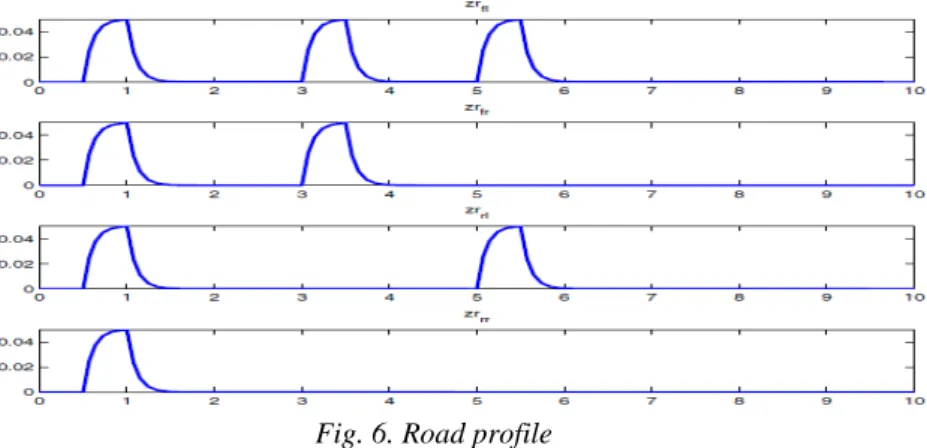
To validate the proposed controller strategy, simulations are performed on a full non linear vehicle model that includes non linear suspension forces based on a Rénault Megane Coupé. The following scenario is used for testing the efficiency of the proposed LPV/H∞:
• The vehicle runs at 60km/h in a straight line on dry road ( µ = 1, where µ represents the adherence to the road).
• A 5cm bump occurs simultaneously on the left and right wheels (from t = 0.5s to t = 1s) to excite the bounce motion.
• Then a 5cm bump occurs on the front wheels (from t = 3s to t = 3.5s) which induces a pitch motion.
• A 5cm bump on the left wheels (from t = 5s to t = 5.5s) and a lateral moment disturbance also occurs in this time that cause the roll vibration.
Fig. 6. Road profile
The parameter scheduling using the motion mode energy method are given in Fig 7. Then, Fig.8, Fig. 9 and Fig.10 illustrate the three main motions: bounce, roll and pitch respectively of the vehicle in the controlled suspensions case and compared to the passive case. Thanks to the LPV suspension controller give us better performance objective for the vehicle when it reduces the amplification of these motions related to the passive suspension model.
Fig. 7 Parameter scheduling Fig. 8 Chasis position
Fig. 9 Roll angle Fig. 10 Pitch angle
6. CONCLUSIONS
The paper has presented a new LPV adaptive suspension control to enhance the vehicle vertical dynamics. A single suspension LPV controller is designed in order to mitigate the vehicle vibrations and therefore guarantee the ride quality. It is worth noting that this strategy permits to have a smooth adaptation when the vehicle has to face road changing without switching between several controllers that would be dedicated to a specific mode. The authors stress that using the LPV framework allows also to simplify the implementation procedure. The next step of this work will be the implementation of this strategy on a test benchmark, available at Gipsa-lab in Grenoble, developed in collabora-tion with a high-technology start up ”SOBEN”. It consists of vehicle equipped with four controllable Electro-Rheological dampers, and of 4 DC motors generating different road profiles separately on each wheel. First results on road estimation are presented in [27].
7. REFERENCES
[1] P. Gaspar, Z. Szabo, J. Bokor, C. Poussot-Vassal, O. Sename, L. Dugard, “Toward global
chassis control by integrating the brake and suspension systems,” in Proceedings of the 5th IFAC Symposium on Advances in Automotive Control, AAC, California, US, August 2007.
[2] C. Poussot-Vassal, O. Sename, L. Dugard, P. Gaspar, Z. Szabo, and J. Bokor, “Attitude and
handling improvements through gain-scheduled suspensions and brakes control,” Control Engineering Practice, vol. 19, no. 3, pp. 252–263, 2011.
[3] S. M. Savaresi, C. Poussot-Vassal, C. Spelta, O. Sename, and L. Dugard, Semi-active
suspension control design for vehicles. Else-vier, 2010.
[4] D. Hrovat, “Survey of advanced suspension developments and related optimal control
applications,” Automatica, vol. 33, no. 10, pp. 1781– 1817, 1997.
[5] G. Koch and T. Kloiber, “Driving state adaptive control of an active vehicle suspension system,”
Control Systems Technology, IEEE Trans-actions on, vol. 22, no. 1, pp. 44–57, Jan 2014.
[6] C. Lauwerys, J. Swevers, and P. Sas, “Robust linear control of an active suspension on a quarter
car test-rig,” Control Engineering Practice, vol. 13, no. 5, pp. 577–586, 2005.
[7] R. Krtolica and D. Hrovat, “Optimal active suspension control based on a half-car model,” in
Decision and Control, 1990., Proceedings of the 29th IEEE Conference on. IEEE, 1990, pp. 2238– 2243.
[8] P.-Y. Sun and H. Chen, “Multiobjective output-feedback suspension control on a half-car
model,” in Control Applications, 2003. CCA 2003. Proceedings of 2003 IEEE Conference on, vol. 1. IEEE, 2003, pp. 290–295.
[9] Y. Zhang and A. Alleyne, “A new approach to half-car active suspen-sion control,” in American
Control Conference, 2003. Proceedings of the 2003, vol. 5. Colorado,US: IEEE, June 2003, pp. 3762–3767.
[10] J. Lu and M. DePoyster, “Multiobjective optimal suspension control to achieve integrated ride
and handling performance,” Control Systems Technology, IEEE Transactions on, vol. 10, no. 6, pp. 807–821, 2002.
[11] K. Hayakawa, K. Matsumoto, M. Yamashita, Y. Suzuki, K. Fujimori, and H. Kimura,
“Robust H∞-output feedback control of decoupled automobile active suspension systems,”
Automatic Control, IEEE Transactions on, vol. 44, no. 2, pp. 392–396, 1999.
[12] I. Fialho and G. J. Balas, “Road adaptive active suspension de-sign using linear
parameter-varying gain-scheduling,” Control Systems Technology, IEEE Transactions on, vol. 10, no. 1, pp. 43–54, 2002.
[13] J. C. Tudon-Martınez, S. Fergani, S. Varrier, O. Sename, L. Dugard, R. Morales-Menendez,
R. Ramirez-Mendoza, “Road adaptive semi-active suspension in a pick-up truck using an lpv
controller,” in Proceedings of Ifac AAC 2013, Tokyo, Japan, September 2013.
[14] N. Zhang, L. Wang, and H. Du, “Motion-mode energy method for vehicle dynamics analysis and
control,” Vehicle System Dynamics, vol. 52, no. 1, pp. 1–25, 2014.
[15] H. Du, N. Zhang, and L. Wang, “Switched control of vehicle sus-pension based on motion-mode
detection,” Vehicle System Dynamics, vol. 52, no. 1, pp. 142–165, 2014.
[16] T. D. Gillespie, Fundamentals of vehicle dynamics, 1992.
[17] U. Kiencke and L. Nielsen, “Automotive control systems: for engine, driveline, and vehicle,”
Measurement Science and Technology, vol. 11, no. 12, p. 1828, 2000.
[18] A. Zin, O. Sename, P. Gaspar, L. Dugard, and J. Bokor, “Robust lpv/ H∞ control for active
suspensions with performance adaptation in view of global chassis control,” Vehicle System Dynamics, vol. 46, no. 10, pp. 889–912, 2008.
[19] J. H. Park and Y. S. Kim, “Decentralized variable structure control for active suspensions based
on a full-car model,” in Control Applications, 1998. Proceedings of the 1998 IEEE International Conference on, vol. 1. IEEE, 1998, pp. 383–387.
[20] D. Sammier, “Sur la modelisation´ et la commande de suspension de vehicules´ automobiles,”
Ph.D. dissertation, Institut National Polytech-nique de Grenoble-INPG, 2001.
[21] J. Wang and D. Wilson, “Multi-objective control of decoupled vehicle suspension systems,”
in Decision and Control, 2001. Proceedings of the 40th IEEE Conference on, vol. 1. IEEE, 2001, pp. 535–540.
[22] M. Doumiati, A. Victorino, A. Charara, and D. Lechner, “Lateral load transfer and normal
forces estimation for vehicle safety: experimental test,” Vehicle System Dynamics, vol. 47, no. 12, pp. 1511–1533, 2009.
[23] S. Fergani, O. Sename, and L. Dugard, “A lpv suspension control with performance
adaptation to roll behavior, embedded in a global vehicle dynamic control strategy,” in Control Conference (ECC), 2013 European, Zurich, Switzerland, July 2013, pp. 1487–1492.
[24] M. Short, M. J. Pont, and Q. Huang, “Simulation of vehicle longi-tudinal dynamics,” Safety
and Reliability of Distributed Embedded Systems, pp. 04–01, 2004.
[25] P. Apkarian and P. Gahinet, “A convex characterization of gain-scheduled H∞ controllers,”
Automatic Control, IEEE Transactions on, vol. 40, no. 5, pp. 853–864, 1995.
[26] C. Scherer, P. Gahinet, and M. Chilali, “Multiobjective output-feedback control via lmi
optimization,” Automatic Control, IEEE Transactions on, vol. 42, no. 7, pp. 896–911, 1997.
[27] J. C. Tudon-Martınez, S. Fergani, O. Sename, R. Morales-Menendez, and L. Dugard,
“Online road profile estimation in automotive vehicles,” in Europena Control Conference, Strasbourg, France, june 2014.