DAMAGE RESPONSE OF SANDWICH PLATES SUBJECT TO
DYNAMIC LOADS
by
Alfonso de Lacruz Alvarez
Naval Architect and Marine Engineer, E.T.S. Ingenieros Navales.
Madrid (Spain), 1993
Submitted to the Department of Ocean Engineering and the Department of Materials Science and Engineering in Partial Fulfillment of the Requirements for the Degrees of
MASTER OF SCIENCE IN NAVAL ARCHITECTURE AND MARINE ENGINEERING
and
MASTER OF SCIENCE IN MATERIALS SCIENCE AND ENGINEERING
at the
MASSACHUSETTS INSTITUTE OF TECHNOLOGY
June, 1995
© Alfonso de Lacruz Alvarez, 1995. All rights reserved.
The author hereby grants to M.I.T. permission to reproduce and to distribute copies of this thesis document in whole or part.
Signature of Author
Depariment of Ocean Engineering
May 12, 1995
Certified by
Tomasz Wierzbicki, Professor of Applied Mechanics Thesis Supervisor, Deparment of Ocean Engineering
Certified by
Frederick J. McGarry, Professor o and Polymer Engineering
Thesis Reader, partment of Materials Science and Engineering
Accepted by
Carl V. Thompson II, Professor of Electronic Materials Chairman, Materials Science and Engineering Departamental Graduate Comitee
Accepted by
Accepte byE A. Douglas ichael, Professo ew ngineering
DAMAGE RESPONSE OF SANDWICH PLATES SUBJECT TO
DYNAMIC LOADS
by
Alfonso de Lacruz Alvarez
Submitted to the Department of Ocean Engineering and the Department of Materials Science and Engineering on May 12, 1995 in Partial Fulfillment of the Requirements for
the Degrees of Master of Science in Naval Architecture and Marine Engineering and Master of Science in Materials Science and Engineering.
ABSTRACT
The objective of this thesis is to derive closed-form solutions for the local impact response of sandwich panels. The indentation load-central deflection characteristic is obtained for three different facesheets: (1) a fully-plastic, isotropic facesheet, (2) an elastic, isotropic facesheet, and (3) an elastic, orthotropic facesheet. The honeycomb core is modeled as a rigid-plastic foundation in the formulation of the local impact response. The analysis is confined to impact situations in which the facesheet deflections are several times its thickness. This allows one to consider the face plate as a membrane on a rigid-plastic foundation since bending moments are negligible when compared to membrane forces. The problem is considered as "quasi-dynamic." The inertia of the projectile is taken
into account while the inertia of the plate is ignored because the mass of the deforming facesheet is negligible compared to that of the projectile. A cornerstone of this analysis is that moving boundary conditions are applied at the extent of deformation. The analytical results are correlated to the experimental work on projectile impact into aluminum facesheets and aluminum honeycomb by W. Goldsmith and J.L. Sackman (1992), and into
graphite/epoxy facesheets and nomex honeycomb by J.E. Williamson (1991). The analytical predictions for the central deflection of the plate when subjected to low velocity impact loads are within 5% error for the fully-plastic, isotropic facesheet and 10% error for the elastic, orthotropic one when the deflections are several times the thickness of the
facesheets.
Thesis Supervisor: Tomasz Wierzbicki Title: Professor of Applied Mechanics
ACKNOWLEDGMENTS
I wish to express my gratitude to everyone who supported me during my studies at
M.I.T. I am specially grateful to Dr. Michelle S. Hoo Fatt without whom I would not have
been able to complete this thesis. Her guidance, patience, encouragement, and continuous
support have been essential during this hard and long last semester in graduate school. I
owe my gratitude to Professor Paul A. Lagace and Professor Werner Goldsmith for the
experimental data used throughout this thesis.
I would also like to thank Professor Tomasz Wierzbicki. Working with him has
been a privilege and a pleasure. Special thanks to my advisor at Ocean Engineering,
Professor Ernst G. Frankel, and to Professor Frederick J. McGarry for their invaluable
advice.
Finally, to the entire M.I.T. Community, these two years have been a worth while
TABLE OF CONTENTS ABSTRACT ... 2 ACKNOWLEDGMENTS ... 4 LIST OF FIGURES ... 7 LIST OF TABLES ... 10 NOM ENCLATURE...11 1. INTRODUCTION ... 14 2. PROBLEM FORMULATION ... 19 2.1. Assumptions ... 20
2.2. Strain - displacement equations ... 21
2.3. Equilibrium of forces and moments ... 22
2.4. Governing equations of motion ... 25
2.5. Summary of plate equilibrium equations ... 27
2.6. Simplifications ... 27
2.7. M oving boundary conditions...28
3. FULLY-PLASTIC, ISOTROPIC FACESHEET OVER A RIGID-PLASTIC FOUNDATION ... 30
3.1. Strain - displacement equations ... 31
3.2. Stress - strain equations ... 32
3.3. Equilibrium of forces and moments ... 34
3.4. Boundary conditions ... 35
3.5. Solution ... 37
3.5.1. Introduction of impact parameters ... 41
3.6. Description of the experimental work ... 44
3.7. Results ... 45
4. ELASTIC, ISOTROPIC FACESHEET OVER A RIGID-PLASTIC FOUNDATION ... 48
4.1. Formulation in polar coordinates ... 48
4.2. Formulation in rectangular coordinates ... 54
4.2.1. Approximate solution by energy method ... 55
4.2.1.1. Solution ... 56
4.2.2. Results ... 60
5. ELASTIC, ORTHOTROPIC FACESHEET OVER A RIGID-PLASTIC FOUNDATION...64
5.1. Equilibrium of forces and moments ... 65
5.2. Approximate solution by energy method ... 69
5.2.1. Solution...70
5.2.1. Introduction of impact parameters ... 73
5.3. Description of the experimental work ... 75
5.4. Results...76
5.4.1. Influence of the tup diameter ... 79
5.4.2. Prediction of the central deflection as a function of the total indentation force...82
6. CONCLUSION AND RECOMMENDATIONS ... 84
7. REFERENCES ... 87
APPENDIX A ... 91
LIST OF FIGURES
Figure 1: Geometry of the sandwich plate under the punch load ... 19
Figure 2: Cross-section of the sandwich plate through y = 0 ... 29
Figure 3: Geometry of the sandwich plate under the punch in polar coordinates ... 30
Figure 4: Cross-section of the sandwich plate ... 36
Figure 5: Exact and approximate relations between the dimensionless central deflection and the dimensionless extent of deformation for a sandwich configuration composed of a fully-plastic, isotropic facesheet and honeycomb core ... 40
Figure 6: Comparison of present analytical solution for the central deflection of the facesheet with the numerical predictions of Jamjian et al. (1994) and the experimental results of Goldsmith and Sackman (1992) ... 47
Figure 7: Geometry of the sandwich plate under a punch load in polar coordinates...49
Figure 8: Vertical deflection versus total indentation force response for the four combinations of facesheet laminates and honeycomb cores proposed for the comparison of the equilibrium equations and energy method solutions...53
Figure 9: Geometry of the sandwich plate under the punch load where P is the total indentation force...54
Figure 10: Comparison between the exact shape function obtained from equilibrium equations in polar coordinates and the selected parabolic function...57
Figure 11: Comparison between the results from equilibrium equations in polar coordinates and those from the approximate energy method in
rectangular coordinates. Case 1: graphite/epoxy on nomex honeycomb ... 60
Figure 12: Comparison between the results from equilibrium equations in polar coordinates and those from the approximate energy method in rectangular coordinates. Case 2: graphite/epoxy on aluminum honeycomb...61
Figure 13: Comparison between the results from equilibrium equations in polar coordinates and those from the approximate energy method in
rectangular coordinates. Case 3: kevlar/epoxy on nomex honeycomb ... 62
Figure 14: Comparison between the results from equilibrium equations in polar coordinates and those from the approximate energy method in
rectangular coordinates. Case 4: kevlar/epoxy on aluminum
honeycomb...63
Figure 15: Geometry of the sandwich plate under the punch load where P is the
total indenting force ... 64
Figure 16: Coordinate systems on the laminate...66
Figure 17: Shape function for the [0/90] laminate at the moment of fracture when
a 12.7 mm tup is used ... 80
Figure 18: Total indentation load versus facesheet central deflection for a [0/90] facesheet and a 25.4 mm core. Comparison of the predicted values with the experimental results for 12.7 mm, 25.4 mm, and 38.1 mm hemispherical tups. The calculation is done by assuming that the
laminate is composed of unidirectional plies ... 80
Figure 19: Total indentation load versus facesheet central deflection for a [0/90] facesheet and a 25.4 mm core. Comparison of the predicted values with the experimental results for 12.7 mm, 25.4 mm, and 38.1 mm
hemispherical tups. The calculation is done using the data of the plain
weave laminate given by Tsang ... 81
Total indentation load versus central deflection of the facesheet for a [0/90/0] facesheet and a 25.4 mm core. Comparison between the experimental results of Williamson (1992) and the analytical solutions.
The diameter of the tup is 25.4 mm ... 82
Total indentation load versus facesheet central deflection for a [0/90/0/90] facesheet and a 25.4 m core. Comparison between the experimental results of Williamson (1992) and the analytical solutions.
The diameter of the tup is 25.4 mm ... 83
Figure 20:
LIST OF TABLES
Table 1: Test matrix selected for Jamjian et al. (1994) to compare their numerical predictions for the central deflection and extent of deformation to the experimental results on the impact response of
aluminum facesheets and aluminum honeycombs by Goldsmith and
Sackman (1992) ... 45
Table 2: Comparison of present analytical solutions for the central deflection and extent of deformation to the experimental results of Goldsmith and
Sackman (1992) and the numerical predictions of Jamjian et al. (1994) ... 46
Table 3: Facesheet and core combinations used to compare the results obtained
using equilibrium equations and energy method ... 53
Table 4: Comparison between the present estimation of the engineering constants and the experimental data given by Tsang for the [0/90]
NOMENCLATURE E Young's modulus EL Longitudinal stiffness ET Transverse stiffness GLT Shear modulus o( Flow stress v Poisson's ratio p Density
qz Crushing resistance in z direction
qxy, qr Shear transmitted by the core to the facesheet h Thickness of the plate
H Thickness of the core rp Radius of the impactor %ux Normal stress in x direction Gy Normal stress in y direction G' Normal stress in z direction
r Normal stress in radial direction
Go Normal stress in hoop direction UX Displacement in x direction
~UY Displacement in y direction UZ Displacement in z direction
u Deflection of midplane (z = h/2) in x or radial direction v Deflection of midplane (z = h/2) in y or hoop direction w Deflection of midplane (z = h/2) in z direction
£y Normal strain in y direction ¥xy Shear strain
Exo Normal strain of the midplane in x direction Cyo Normal strain of the midplane in y direction Yxyo Shear strain of the midplane
Kx Curvature in x direction Ky Curvature in y direction Ky Twisting curvature
Nx In-plane axial force per unit length in x direction Ny In-plane axial force per unit length in y direction
N.y In-plane shear force per unit length
Mx Bending moment in x direction My Bending moment in y direction
Mxy Torsional moment
Qx, Qy Shear forces
ur Displacement in radial direction
ue Displacement in hoop direction
Er Normal strain in radial direction ce Normal strain in tangential direction
%o Shear strain
Ero Normal strain of the midplane in radial direction
0
oo Normal strain of the midplane in hoop direction
Yroo Shear strain of the midplane
Kr Curvature in radial direction
'cO Curvature in tangential direction
No In-plane axial force per unit length in hoop direction
No In-plane shear force per unit length
Mx Bending moment in radial direction
My Bending moment in hoop direction
M,:, Torsional moment
C Extensional rigidity
D Bending or flexural rigidity
P Total indentation load
Extent of deformation
FI Total potential energy
U Internal strain energy
Ub Internal energy due to bending moments
Um Internal energy due to membrane forces
W Work due to applied external forces
Ek Kinetic energy
Mo Mass of the projectile
VO Velocity of the projectile
Mp Mass of the facesheet under the projectile
m Mass density of the facesheet per unit area
Fplae Inertia of the facesheet
1. INTRODUCTION
During the last three decades, sandwich structures have been steadily replacing
wood, aluminum, steel and solid fiberglass in the marine industry. Initially they were only
used for small crafts because their behavior was not completely understood and the
shipbuilding industry was overly conservative. Today, we see them being used in
structures weighing more than a hundred tonnes such as ship hulls and superstructures,
and submersibles. The development has been even more prevalent in high performance
applications because of the great advantages they offer over classical configurations. For
example, all the high performance sailing yachts such as America's Cup boats, Whitbread
60's, or round-the-world multihulls are built using composite sandwich panels. The most
common configuration for these applications is graphite/epoxy facesheets and honeycomb
core. They are also extensively used in other applications such as racing powerboats and
fast military crafts where good impact resistance, high stiffness-to-weight ratio, and high
strength-to-weight ratio are important requirements.
Sandwich structures exhibit several advantages over conventional structures that
have favored their introduction in many structural applications [1, 27, 34]: (1) they have high bending-stiffness-to-weight ratios; (2) they show good stability under compressive
forces in the plane of the panel; (3) their lightweight core material acts as an energy
absorber during impact events; (4) they allow more usable interior volume when compared
to stiffened panels; (5) they have excellent thermal and acoustic insulation capabilities.
The idea behind a sandwich structure is the use of a low density core between two
faceplates to increase the moment of inertia and, therefore, the bending stiffness of the
panel without increasing the weight. In an ideal sandwich, two thin facesheets or skins are
connected or bonded to two sets of ribs that run perpendicular to each other. In order for
thickness, and the cells that the ribs form must be small enough not to fail locally under
lateral pressure or concentrated loads [5]. This ideal sandwich is difficult to fabricate and
has been substituted for more practical configurations such as honeycomb and balsa cores.
These are almost ideal except for the discontinuity of the ribs in the longitudinal and
transverse directions.
The sandwich configuration is similar to an I-beam in geometry and in the way loads are transferred in it. The facesheets are like the flanges of the beam one being in
tension and the other in compression when the beam is loaded. The core material acts like
the web of the beam resisting compression and transverse shear loads. A structural
adhesive capable of transferring shear forces from the skins to the core is used for bonding
the two constituents of the sandwich.
Facesheet materials
Fiber reinforced laminates are the most common choice for the facesheets of
sandwich panels in marine applications. There is a clear distinction between the composite
materials used for high performance and commercial applications. Chopped, woven or
unidirectional E-glass laminates are almost the only fibers used in commercial applications
because they are inexpensive. On the other hand, woven and mostly unidirectional high
modulus fibers such as graphite, kevlar, or boron are used in high performance structures.
Fiber reinforced laminates present some important characteristics that make them
more attractive than metals for certain applications. First and foremost, they have a higher
specific strength and stiffness than metals. This allows important reductions of structural
weight and consequently improvements in range, speed, and payload. Second, an
important characteristic is their adaptability to specific loading or structural requirements
by aligning fibers in the appropriate directions. They show, in general, good fatigue
characteristics and exceptional characteristics in the case of carbon or boron fibers. They
reductions in maintenance costs. For commercial applications, composite materials offer a
higher quality of the finished products with smooth surfaces, excellent appearance, and
ease of the maintenance and repair operations. Other advantages include good toughness
behavior, non-magnetic and dielectric properties, and low thermal conductivity. Despite all
the advantages composite materials have to offer, uncertainty in their complex behavior
and the lack of acceptance in replacing them for better understood materials have resulted
in their underutilized potential.
Core materials
Three types of core materials are generally used in marine applications: wood
(mainly balsa), polystyrene, polyvinyl chloride (PVC), polyurethane and acrylic foams, and
aramid paper or aluminum honeycomb [31]. Balsa cores have a high compressive strength
and modulus, high shear strength, and low cost, but the high resin and water absorption
have made them undesirable for some marine applications. Foam cores can be divided in
two groups: those with low cost and low mechanical properties such as polyurethane or
polystyrene foams and those with good mechanical properties and higher cost like PVC or
acrylic foams. Both types are generally used for commercial applications depending their
choice on the specific mechanical requirements. Although they show excellent mechanical
properties, honeycomb cores are only used for high performance applications due to their
high cost. Their reduced weight and high compressive and transverse shear strengths make
them the only choice for those applications even though high density PVC is also used
where attachments are to be made.
Due to increasing use of sandwich structures, it is important to clearly understand
their complex behavior so that they may be properly designed for particular applications.
Many studies are being carried out to increase our knowledge on these configurations
especially in the aircraft industry. In the marine industry, one area of major concern is the
part of the hull due to impact loads. These loads include the collision with a rock or
grounding, the collision with another vessel, or the striking of small submerged or floating
objects in the water. A particular case of impact that affect the forward sections of fast
crafts is that due to slamming loads. These loads are generated by the impact of waves
onto hulls or by the sudden submergence of the bow into the water. Although it is not
exactly a projectile impact event, it can be modeled as one by considering the loading as a
uniformly distributed impulsive load over a localized or "patch" region of the plate [34,
35].
It is essential to understand the behavior of the sandwich panel during an impact
event in order to prevent possible damage. There are several numerical codes for analyzing
the impact response of a sandwich plate that show good correlation with experimental
data until the failure of the facesheet such as those by Tsang [24] and Lie [25]. The
objective of this thesis is to derive simple closed-form solutions for the impact response of
sandwich panels. These solutions may be used to improve the design of sandwich hulls
against impact loads.
During impact, the deformation of the bottom and side panels of the hull can be
characterized by two modes: (1) overall bending of the panel and (2) local deformation of
the outer facesheet and the core but no deformation of the inner facesheet. If the overall
panel is assumed of infinite stiffness, only localized damage of the outer facesheet and the
core will occur. The inner laminate of the sandwich remains intact and the outer one
suffers permanent deformation due to plastic deformation of the core. On the other hand,
for panels of overall finite stiffness, both the inner and the outer laminates undergo
bending deformation.
Although the global effect should be study in order to completely understand the
failure mechanisms due to impact loads, the complexity of the plate response and the
i.e., localized damage of the top facesheet and the core. Moreover, only low velocity
impact will be considered to take advantage of the existing experimental work.
First, a general formulation of the dynamic response of a sandwich plate is given in
Chapter 2. Then, three different sandwich configurations composed of three different
facesheet materials and honeycomb cores are considered: a fully-plastic, isotropic
facesheet in Chapter 3; an elastic, isotropic facesheet in Chapter 4; and an elastic,
orthotropic facesheet in Chapter 5. The analytical results for the fully-plastic, isotropic
facesheet are compared to the experimental work on projectile impact of aluminum
facesheets with aluminum honeycomb core by W. Goldsmith and J.L. Sackman [15], while
those for the elastic, orthotropic plate are compared to the work on projectile impact of
graphite/epoxy faceplates with nomex honeycomb core by J.E. Williamson [23]. In both
experimental papers, the deflections were several times the thickness of the facesheets. In
2. PROBLEM FORMULATION
To study the local impact response of a sandwich plate, consider the top facesheet
fixed onto a rigid foundation. The bottom laminate of the sandwich remains intact while
the top one undergoes permanent deformation as the core crushes under the impacting
force. The deformation considered is very localized so that the impact occurs over an
infinite plate.
The sandwich structure is composed by two facesheets and a rigid-plastic
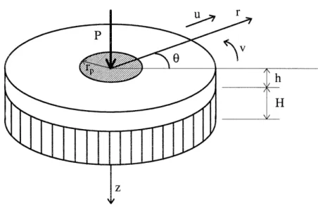
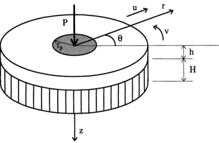
honeycomb core. The geometry of the plate is defined by the facesheet thickness h, and
honeycomb thickness H as shown in Figure 1. The faceplate is characterized by the
Young's modulus E, density p, and Poisson's ratio v. The projectile impact force is
represented by a quasi-static punch load acting on a circular area of radius rp. During
impact, the shear transmitted by the core to the plate is denoted qy, and the crushing
resistance of the honeycomb is denoted qz.
qZ
h H
2.1. ASSUMPTIONS
1. Since the plate is considered to be infinite, the thickness of the facesheets is small
compared to the other dimensions of the plate. Therefore, the facesheets are considered
thin plates and the normal stress in z direction can be neglected i.e., plane stress conditions
(oz << ox, y X Oz = 0). Furthermore, due to the fact that the facesheet is thin, it is under
a two dimensional state of stress (rzx = Xy = 0).
2. Plane sections remain plane and perpendicular to the midplane after deformation
aw aw
u= ua- zx x ~ ; u= ; v-y u = w (1)
where u, v and w are the deflections of the midplane (z = h/2).
3. For a given central deflection wo, the extent of deformation is denoted by 4. The plate is
flat and the facesheets are securely bonded to the honeycomb core. Therefore, since the
displacements in x and y directions are equal to zero at x = 0, y = 0 and at x, y larger
than the extent of the deformation, they can be neglected when compared to the vertical
deflection,
u=O0 and v0.
Therefore, the deflection of the plate is due to the displacement of the middle surface
2.2. STRAIN - DISPLACEMENT EQUATIONS
The relationships between the normal and shear strains and the displacements can
be calculated using Equation (1) and taking into account that the deflections are large and
the squares of the slopes are not negligible
aJu .__3ux
S
+
£ = X = E + zx auy ~y = a y = , + z, (2) au au xy= x + a = Yo + Zxy ¥ Jy axwhere exo, , and exyo are the strains of the neutral surface, and :x, ry, and xy are the
curvatures. The strains of the midplane and the curvatures are defined as
au I aw2 X-
ax
+2
ax
av 1 (aw 2 .Yo 2 ayI (3) D~u av Jw aw YXYo I + I + ay + ax) ax ay' anda2W Kx ax2 DxW ~}2w iy = - ay2 (4) D2w Kxy =-2 axay.
2.3. EQUILIBRIUM OF FORCES AND MOMENTS
The stresses in the plate are written in terms of the strains using Hooke's law
E (e + vey) ax
-E (e
CY
Y 1-v1-v ( +
~e)
(5)
E
Y=2(1
+
v)y
Once the relationship between stresses and strains has been established, the in-plane forces
per unit length are calculated as the integral of the stresses over the thickness of the plate
h12
N
= J|axdz
=C(Ex"
+
Vo)-h12
hi2
N = f aydz = C(c, + (6)
h/2 V(1 )
Nx = xydz = C 2 YOo -h/2
where C = Eh Eh is the extensional rigidity.
1 - V2
The relationship between membrane forces and displacements is derived by
introducing Equations (3) into Equations (6)
N C au Nx
Iax
NY=C
D
N~c~
a
y
= C
( 1-
)
2 +V + D 2+ V -+ _ _
DU _ VDW 2A+ V- _
a3x2
x)
((au
+ a)
DW W + a y .Bending moments are also calculated from the stress-strain relationships by
integration of stresses and moment arms
h12 M = caxzdz -hl2 h12 My = J yzdz -hi 2 hi2 MXY = I/
lx'zdz
=D(1
- V)KXY, -hli2 (7) = D(C + VKY) = D(KC +CX)
(8) I DW 2 2 Dx I aW 2 2 DyEh3
where D = 12(1 - v2 ) is the bending or flexural rigidity.
Equilibrium of the facesheet gives
aNyX idy = q +hp in x-direction, DNxv .X
aNy
N+
= q, ax ay +hp at2 in y-direction, and aQx aQY+ + a+ ax ayN
a2w X ax2 a2W+ 2N
xy axayxy
+
a2W aw (Nx N ay2+ x Y -aY- a ax +(p- q) = ph a2W at2 in z-direction.On the other hand, moment equilibrium gives
aM M + =x Qx ax ax in x-direction, and (9) (10) + y aNyx aw (aNny ay ax (11) (12) + aN + ay
ax
+ a = Q (13)ax ax
in y-direction, where Qx and Qy are shear forces.
2.4. GOVERNING EQUATIONS OF MOTION
The combination of the equilibrium equations in the three directions, Equations
(9), (10) and (11), gives
aQX
+ aQY
+N
a2wax ay ax2
+hp
a
+
-
V
q pat2 +ay aw+2N. -
+ NY
~axay+
hp
a2V+(p
If moment equilibrium equations, Equations (12) and (13), are introduced into Equation
(14),
a
2
MyN
ay a2wax2
+ 2N, + hp a2 ) aw axayEquations (4) are introduced into Equations (8) to get an explicit relationship between
bending moments and displacements
awx + qxy ax a2w ay2 - q) a2w = hp
at
2 (14) a2Mxy ax+y axay a2M ax2 aw + ax qY a2u aw+
hp a 12 + aw qy at2ay;-+ N
a w ay2 +(p-q) = hp a2w at2 (15)M = D(x + VK,) Y= D(Y + M = D( 1-VKx) = -D(ax + v ay)
=
_ a2w Way2 V)Kx =-(
-a2W + V -ax2 a2W v) yaxy
Substituting, Equations (16), into Equation (15) gives
a4W
+'
+N
ay4 ) 2w x +2Nx .ax ayawx +a2
ay = 2p W (17) = hp at 2 , (17)where V =
a
2 + is the Laplacian operator.ax2 ay2 (16) + 2 ax2ayW2
+
qw
+ -x, ax or DV4w- Nx a2 ax22N
aw2 xay
N¥ 2 w- N
ay2 2W= (p - qz) - hp
a2-. (18) -D a4W ax4 + hpaU + aw q, hp a2V
+ (p - qz) at2 ay at2 aw q, hp -a2U -ax at2- aw
q, hp a2V ay at'2.5. SUMMARY OF PLATE EQUILIBRIUM EQUATIONS
The equilibrium equations of the plate under the quasi-static punch load are:
aNx a a2u
ax
+ ay q + hpat (9)a
N.
aa2,
N + = q + hp (10) ax ay at V4w N a2 Waw
a2wD
~2N
.aw -N -
,+h
DV4w -N ax2 2NXY axay Ny a ax at2
ay
2
~~~au
aw a2v' a2w _y qy x + hp atv) = ( p - q ) - hp (18) -- Iq~~~~~~~~~~~hp- ~~~~~~~(18)ay~Y
at,
t
The above expression, Equation (18), is the governing equation for the plate vertical deflection including both membrane forces and bending moments.
2.6. SIMPLIFICATIONS
1. When the deflections of the plate are large compared to the thickness as in the
experimental work by Goldsmith and Sackman [15] and Williamson [23], plate bending
resistance is negligible when compared to membrane one (D = 0). However, the resulting differential equation remains non-linear and can not be integrated directly. In order to estimate the value of the deflection, three cases that can be applied to different materials used in the marine industry will be considered: a fully-plastic, isotropic plate over a
rigid-plastic foundation, an elastic, isotropic plate over a rigid-rigid-plastic foundation, and an elastic,
orthotropic plate over a rigid-plastic foundation.
2. The impact response of the sandwich plate is considered to be a "quasi-dynamic"
process [10]. The inertia of the facesheet is neglected compared to the inertia of the
projectile because the mass of the projectile is much larger than the mass of the deforming
top plate.
2.7. MOVING BOUNDARY CONDITIONS
Since a local impact event is considered, the plate is bounded at infinity. However,
deformations occur within a finite region , as shown in Figure 2, that depends on the load
intensity. Boundary conditions or, in this case, moving boundary conditions, are applied at
4, i.e., the extent of deformation. These are:
1. The vertical deflection is zero at the extent of deformation,
w=0 at r=t,
(19)where r2= x2+ y2.
2. The condition of kinematic continuity has to be satisfied at the moving boundary t,
Eat]+
[
= 0 atr=t,
where [ ] symbolizes a jump in value across the moving boundary.
Honeycomb corn
Figure 2: Cross-section of the sandwich plate through y = 0.
3. FULLY-PLASTIC, ISOTROPIC FACESHEET OVER A RIGID-PLASTIC FOUNDATION
The sandwich structure is composed by two fully-plastic, homogeneous, and
isotropic facesheets and a rigid-plastic honeycomb core. The plate is considered to have
infinite radius, facesheet thickness h, and honeycomb thickness H as shown in Figure 3.
The facesheet is characterized by the Young's modulus E, flow stress , and Poisson's
ratio v. During deformation, the shear transferred by the core to the plate is denoted qr,
and the crushing resistance of the honeycomb is denoted qz.
Figure 3: Geometry of the sandwich plate under the punch in polar coordinates.
The problem to be solved is that of the local effect of a quasi-static punch load
acting at the center of a circular sandwich plate when the deflections are large compared
to the thickness of the facesheets. The plate equations will be reformulated in polar
=
= 0and v ,
and v = 0,30
where v is the displacement in the hoop direction.
For a given central deflection wo, the extent of deformation is denoted by ,. The
plate is flat and the facesheets are securely bonded to the honeycomb core. Therefore,
since the radial displacement u is equal to zero at r smaller than rp and at r larger than the
extend of the deformation, it can be neglected when compared to the vertical deflection
everywhere in the plate (u = 0).
3.1. STRAIN - DISPLACEMENT EQUATIONS
The relationships between the normal and shear strains and the displacements in
polar coordinates are calculated by transforming the relationships in rectangular
coordinates to polar coordinates
r = ro £o = Eo 7,e = o
+ Zr
+ ZKice + ZK,e, (22)where Eo, o and e0o are the strains of the neutral surface, and r, K, and ro are the
curvatures. The strains of the midplane and the curvatures are defined as
Du 1 (a3w 1 aw 2
=_
-av
+- u ° (23) cor
+ r0 I au av V=--+ -- =0
r
aO
ar
r
and D2w 'Kr 2ar:
K = __l
aw1
a2w 1aw
K~ = _ a % 2 = (24)r r
r
202
r r
2
2w
2aw
K~ = rar0
+ =~~~~0.r2 0ao3.2. STRESS - STRAIN EQUATIONS
In-plane forces per unit length are calculated using Hooke's law to formulate the relationships between stresses and strains and a transformation of reference system to polar coordinates Nr = C(ro + V0 )
No
= C(o + ver (25)N =C(l
-
V)
2 Ehwhere C = E is the extensional rigidity.
Membrane forces are expressed in terms of the vertical displacement of the plate
by introducing Equations (23) into Equations (25)
N =_
N2 D r0 N=-2 arjN, =0.
(26) (27) (28)Bending moments are derived in the same way as in the rectangular coordinate system
formulation but transforming the coordinate system to polar
Mr = D(K + K0)
ME = D(Kc + VKr)
where D = Eh
3
12(1- v2) is the bending or flexural rigidity.
Equations (24) are introduced into Equations (29) to derive an explicit relationship
between bending moments and the vertical displacement
M -JD( a2w Mr =_2 = + v
aw
r r (30) (31) va2W) (29) M = I I - V "OD L X'O 1 2Mr0 = 0.
3.3. EQUILIBRIUM OF FORCES AND MOMENTS
The equilibrium of forces acting in radial direction gives
0JN
r-
+ (N - N) - q =0.
Dr (33)
Furthermore, since the displacement of the plate is only in vertical direction (u, v = 0), the
shear transmitted by the core to the plate is zero (qr = 0). The resulting equilibrium
equation in radial direction is
Nr -N 0) =
0.
(34)The moment equilibrium equation of the facesheet can be written as
( r-Mr
+ M - M - rNrw = qzr.
Dr Dr Dr (35)
Equation (35) is expressed in terms of the vertical displacement of the plate by introducing
Equations (30) and (31) Dr [_ O3w 1 ar2w
-ri-Dri-+-
r r
a + r a = qzr. r2 + rNr (36) (32)r aN + (
DrEquation (36) is the governing differential equation for the vertical deflection of the
facesheet in polar coordinates that includes not only membrane forces but also bending
moments.
In the experiments conducted by Goldsmith and Sackman [15] that will be used to
validate the analytical results for the fully-plastic, isotropic plate, the deflections are
several times the thickness of the facesheet. Being under large deflection conditions,
bending moments can be neglected when compared to membrane forces (D = 0) and
Equation (36) simplifies into
a (rNr aw) qz. (37)
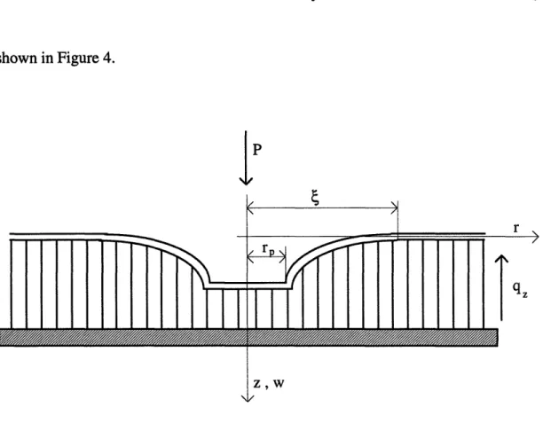
3.4. BOUNDARY CONDITIONS
This governing equation for the facesheet vertical deflection is subjected to the
following boundary conditions:
1. When subjected to large deflections, the total shear force of the plate is equal to the
total indentation force P plus the crushing resistance of the honeycomb under the punch
N w (2r) = -(P - qr
2)atr=rp.
(38)
w=O atr=
as shown in Figure 4. PI
/1 r A 1 H \I rzw
Figure 4: Cross-section of the sandwich plate.
Because the extent of deformation or boundary between the deformed and non-deformed regions changes during the loading process, the condition of kinematic continuity of the vertical deflection must be also satisfied at ~,
[W + [ aw = 0 at r =,
a
~t Dt DrJ (40)
where [ ] symbolizes a jump across the moving boundary. Since for r greater than t
K - ) _ _ . f 2! I__._ __ __ _ \ - l _ I ._ I I - - - - -M
I
M M M M M M M I M EM M M M M M M (39) %. I'=0
and awat
=0,
Equation (40) can be modify to give
aw a aw =
at
at r
atr= .
(41)3.5. SOLUTION
The governing differential equation for the vertical deflection of the facesheet is
a ( r
aDr (
aw = qzr.
Dr (37)
Integrating Equation (37) with respect to the radial coordinate r gives
Nr aw
=
qzr + C,Dr 2 r (42)
The integration constant C1 is calculated from this expression, Equation (42) using the
first boundary condition
- P
Since the plate is considered as fully-plastic and isotropic, the radial membrane force
reaches full yield when
N= N = h.
r
0
Equation (42) can be rewritten using this fully-plastic membrane force as
N aw = qr
2
P
2cr
Integrating Equation (45) with respect to the radial coordinate r gives
q~r2
P
N
=
w
ln r
+
C
2
.
N0 4 27c
(46)
The integration constant C2 can be calculated using the second boundary condition (w = 0
at r = t) and Equation (46)
P
-ln-27
q4 (47) 2 4If the value of C2is introduced in Equation (46),
Nw= P
In.
q(42
° 2n r 4 - r2), (48)
where 4 is function of the total indentation force P.
(44)
This relation between the extent of deformation and the total indentation load can
be calculated using the condition of kinematic continuity of the vertical deflection at the
moving boundary. In a quasi-static problem, the monotonically increasing load can be
considered a time-like parameter and used to substitute the time in Equation (41)
3Jw + ~ 34 -W = 0 atr=4.
DP
P r
The relationship between , and P is obtained applying this condition to Equation (48)
P = qz2.
(49)
(50)
The central deflection of the plate is calculated for r = rp as a function of the extent of deformation from Equation (48) and the previous relationship between P and t
NoW = q4'
2
This relationship between w and ,
following dimensionless variables:
In cn be non-dimensional
q (4
2- r2). by introducing the(51)(51)r 4 P
can be non-dimensionalized by introducing the
- 4Now°
= =- and w = 2.
1~~~~~qzrp
(52)The present solution for the vertical deflection of the facesheet given by Equation (51) can
= -2
~2
4 _ t2(53)
This relationship between the dimensionless extent of deformation and the dimensionless
central deflection, Equation (53), can be approximated by a parabolic function with an
appropriate coefficient that is calculated via minimization of the relative error
(54)
(W ) = 2.
8(
- 1)2.Both the exact solution and the parabolic approximation are shown in Figure 5.
Exact analytical solution, Equation (53)
... Approximation, Equation (54)
1.5 2 2.5 3 3.5
Figure 5: Exact and approximate relations between the dimensionless central deflection
and the dimensionless extent of deformation for a sandwich configuration composed of a
fully-plastic, isotropic facesheet and honeycomb core.
20 Wo 18 16 14 12 10 8 6 4 2 0
3.5.1. Introduction of impact parameters
If the impacting object is considered as a rigid cylinder of mass Mo and initial
velocity Vo, the total indentation force or contact P that acts over the facesheet of the
sandwich is equal to the inertia force of the projectile
P = -M,
a2.
(55)
at2
The equations of the quasi-static approximation are still valid if the plate inertia force can
be neglected compared to the inertia of the projectile. Therefore, if Fplate is the inertia of the
facesheet and Fpoj is the inertia of the projectile,
Fat
<1.
(56)proj
The inertia force of the top face can be calculated as the integral of the mass of the plate
times the vertical acceleration
Fpt2,,
=
dr
= 2 m
--
r-rm
r
r
,
(57)
0 ~~~~~~~~~~0
where m is the mass density of facesheet per unit area. Since the acceleration is maximum
at r = rp and decreases as the radius increases, the upper bound of the inertia force of the
3'% 2 , %
Filate < 2Cmf r a-2r = 7Ct2m
at
(58)0
Once the inertia of the projectile given by Equation (55) and the inertia of the facesheet
given by Equation (58) are known, the relation between them can be established as
pLate,< p (59)
Fp.roj MO Mo
where Mp denotes the mass of the facesheet under the projectile. In the above relationship
and for the experimental values that Goldsmith and Sackman used in their tests, the
relation / rp varies from 1 to a maximum value of 3.5, and the mass of the projectile
under the punch takes a value of Mp = 0.01Mo. The ratio between the inertia of the plate
and the inertia of the projectile varies from 0.01 to 0.035. This result validates the
assumption that considered the inertia of the plate negligible when compared to the inertia
of the projectile. Therefore, the equations derived under quasi-static assumptions will stil
be useful to estimate the extent of deformation and the final central deflection in terms of
the experimental parameters.
An energy balance between the kinetic energy transmitted by the projectile to the
facesheet and the plastic work required to plastically deform the plate and crush the
honeycomb can be established to relate the extent of deformation and the central
deflection with the experimental parameters (Mo, V0, a.o, q, rp and h). The kinetic energy
that the projectile transmits to the plate is function of its mass and initial speed
1
Ek = -Vo (60)
On the other hand, the plastic work on the sandwich plate includes the energy required to
crush the honeycomb plus the energy required to plastically deform the facesheet. It is
calculated from the total indentation force
(61)
Eplastic = P(w0)dw =
'P(4)
D d4fp a
where aw /
t
can be calculated from Equation (48) and P(4) is known from Equation (50). The result of the integral isplastic
4(;fi
h~
[(r ) [
)
]
+
(62)Finally, the relationship between the extent of deformation and the experimental
parameters is obtained balancing both the kinetic energy communicated to the facesheet by
the projectile and the plastic work required to deform the sandwich
=
E,=~Mo~~~~~~6(,
M
k
V
~~~~~I ~2hi
=~
P
l~
+ -
oh
-
-Il
+
1lJ
=
Epaic
plasti
c
'
Equation (63) can be rewritten in a
variables given by Equation (52)
non-dimensional form by using the dimensionless
(64) (63)
- = 4 4
= Moyo
a~h
Ek ~ = ' . .' .(65)2
k '~/ 2r4·
Equation (64) in conjunction with Equation (53) allows the calculation of the vertical
deflection of the facesheet by a previous evaluation of the extent of deformation as a
function of the experimental parameters (Mo, Vo, aO, q, rp and h). Once the extent of deformation is known, the total indentation force P can also be calculated.
3.6. DESCRIPTION OF THE EXPERIMENTAL WORK
The present analysis will be validated using the experimental work by W.
Goldsmith and J.L. Sackman [15] on the impact of a flat-nosed cylindrical impactor on
both bare honeycomb and sandwich plates with aluminum facesheets and aluminum
honeycomb. In both cases the targets were supported by a rigid foundation while the
sandwich plate was also tested under simply-supported conditions.
The tests were subjected to the following conditions: the impacting area was
smaller than the lateral extent of the samples, the thickness of the core was limited to
19 mm., the diameter of the impactor was greater than cell dimensions and plate thickness,
and impact velocities ranged from 10 to 40 m/s in order to just attain densification of the
targets.
The present solution will be also be compared to a numerical approximation by M.
Jamjian, J.L. Sackman and W. Goldsmith [12]. In their paper, the response of a thin
infinite plate over a honeycomb foundation impacted by a cylindrical impactor was analyzed. The facesheet was considered as rigid-perfectly-plastic and the honeycomb as a
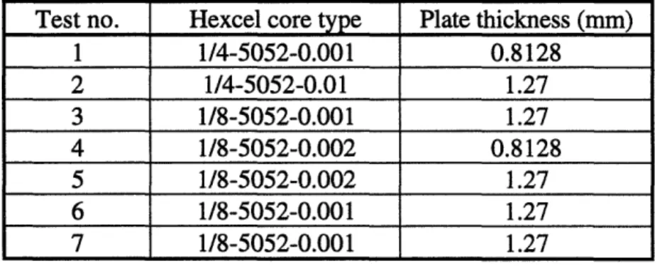
shear forces were retained in the derivation. Seven tests with different experimental
parameters were chosen from the ones performed by Goldsmith and Sackman [15] and
used to correlate the numerical solution. The material used was an 5052 H32 aluminum
facesheet and 5052 aluminum honeycomb. The tests were performed with samples of
different facesheet thicknesses and core types. The radius of the impactor used was 36.56
mm. The experimental matrix can be seen in Table 1.
Test no. Hexcel core type Plate thickness (mm)
1 1/4-5052-0.001 0.8128 2 1/4-5052-0.01 1.27 3 1/8-5052-0.001 1.27 4 1/8-5052-0.002 0.8128 5 1/8-5052-0.002 1.27 6 1/8-5052-0.001 1.27 7 1/8-5052-0.001 1.27
Table 1: Test matrix selected for Jamjian et al. (1994) to compare their numerical
predictions for the central deflection and extent of deformation to the experimental results
on the impact response of aluminum facesheets and aluminum honeycombs by Goldsmith
and Sackman (1992).
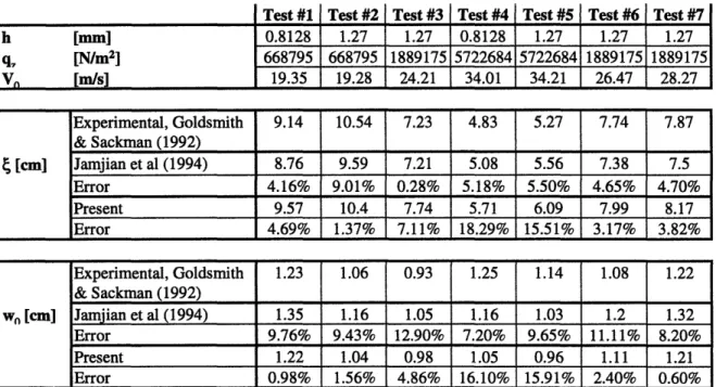
3.7. RESULTS
The derived analytical equations will be correlated against the experimental results
on low velocity impact by Goldsmith and Sackman [15] and the numerical predictions by
Jamjian et al. [12]. The input data, the experimental results, the predictions by Jamjian et
Jamjian et al. to validate their approach are presented in Table 2. The relative errors for
both the numerical approximation by Jamjian et al. and the present analytical result when
compared to the experimental data are also included.
h [mm] q7 [N/m 2 ] Vn [m/s] Test #1 0.8128 668795 19.35 Test #2 1.27 668795 19.28 Test #3 1.27 1889175 24.21 Test #4 0.8128 5722684 34.01 Test #5 1.27 5722684 34.21 Test #6 1.27 1889175 26.47 Test #7 1.27 1889175 28.27 Experimental, Goldsmith 9.14 10.54 7.23 4.83 5.27 7.74 7.87 & Sackman (1992) _ l l l l ll 4 [cm] Jamjian et al (1994) 8.76 9.59 7.21 5.08 5.56 7.38 7.5 Error 4.16% 9.01% 0.28% 5.18% 5.50% 4.65% 4.70% Present 9.57 10.4 7.74 5.71 6.09 7.99 8.17 Error 4.69% 1.37% 7.11% 18.29% 15.51% 3.17% 3.82% Experimental, Goldsmith 1.23 1.06 0.93 1.25 1.14 1.08 1.22
& Sackman (1992) LIl
wn [cm] Jamjian et al (1994) 1.35 1.16 1.05 1.16 1.03 1.2 1.32
Error 9.76% 9.43% 12.90% 7.20% 9.65% 11.11% 8.20%
Present 1.22 1.04 0.98 1.05 0.96 1.11 1.21
Error 0.98% 1.56% 4.86% 16.10% 15.91% 2.40% 0.60%
rp = 3.66 cm o = 1.65 108N/m2 M0= 0.839 Kg
Table 2: Comparison of present analytical solutions for the central deflection and extent of
deformation to the experimental results of Goldsmith and Sackman (1992) and the
numerical predictions of Jamjian et al. (1994).
It can be seen from Table 2 that the present analytical predictions are within 5%
error for low impact velocities when compared to the experimental results. Only the tests
#4 and #5 with the highest impact velocities are out of the 5% error range but closer to
16% error. On the other hand, for the extent of deformation, the analytical results are
highest impact velocities for which the error reaches 19%. A reasonable explanation for
this increment in the error is that the problem was considered "quasi-dynamic" and the
inertia of the plate was neglected. As the impactor velocity increases, the relative
importance of the inertia of the facesheet also increases. It is also noticeable that the error
achieved using these simple closed-form solutions is lower than that obtained by Jamjian et
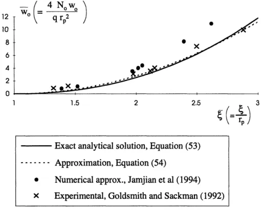
al. using a numerical approximation. This fact can be also observed in Figure 6 where the
present analytical solutions are compared to the experimental results by Goldsmith and
Sackman and the numerical approximation by Jamjian et al.
4 No wo Iz 10 8 6 4 2 n 1 1 1.5 2 2.5 3
Figure 6: Comparison of present analytical solution for the central deflection of the
facesheet to the numerical predictions of Jamjian et al. (1994) and the experimental results
of Goldsmith and Sackman (1992).
Exact analytical solution, Equation (53) ... Approximation, Equation (54)
* Numerical approx., Jamjian et al (1994)
4. ELASTIC, ISOTROPIC FACESHEET OVER A RIGID-PLASTIC FOUNDATION
This problem will be solved using equilibrium equations and energy methods in
polar and rectangular coordinates, respectively. The reason for solving the problem in both
ways will become apparent when a closed-form solution for the elastic, isotropic facesheet
is presented.
4.1. FORMULATION IN POLAR COORDINATES
The sandwich structure is composed by two elastic, homogeneous, and isotropic
facesheets and a fully-plastic honeycomb core. The plate is considered to be infinite, with
facesheet thickness h, and honeycomb thickness H as shown in Figure 7. The facesheet is
characterized by the Young's modulus E, and Poisson's ratio v . During impact, the shear
transmitted by the core to the facesheet is denoted qr, and the crushing resistance of the
honeycomb is denoted qz. The problem to be solved is that of the local effect of a
quasi-static punch load acting at the center of a circular sandwich plate when the deflections are
large compared to the thickness of the facesheets. The same moving boundary conditions
Figure 7: Geometry of the sandwich plate under a punch load in polar coordinates.
4.1.1. Solution
Recall from Chapter 3 that the governing differential equation for the vertical
deflection of the facesheet to be solved is
a- ( rNr
3r
aw)
Ark
qzr.Integrating Equation (66) with respect to the radial coordinate r gives
(66)
Nr aw
r D
q + C,
2 r
where the integration constant Cl is calculated using the first boundary condition
C P (68)
27c
Rewriting Equation (67) after the introduction of the value of the integration constant Cl
gives
N w = qzr -P (69)
r ar 2 27r
where the extent of deformation , is function of the total indentation force P.
The relation between , and P can be calculated using the condition of kinematic
continuity of the vertical deflection at the moving boundary. In a quasi-static problem, the
monotonically increasing load can be considered a time-like parameter and used to
substitute the time in the Equation (66)
aw
+ at
=W 0 atr=. (70)aP aP r
The relation between the total indentation load and the extent of deformation is obtained
combining this kinematic continuity condition, Equation (70), with the first boundary
condition of the problem
P
= q/42.(71)
Introducing the expression of the membrane force in the radial direction as a
C
aw
= qr- P (72)Eh
where C = E is the extensional rigidity. Finally, rewriting Equation (72) to get an
1- V2
expression of the slope results in
aJw 1 P
= qzr (73)
Or 7 r
If Equation (73) is integrated with respect to r, the central deflection of the facesheet is
obtained in terms of the total indentation load and the extent of deformation
W
= j3(qzr
- -f3.c(qzr
- sr)dr.(74)
Jrp 7crrr C 7cr
Since this equation can not be integrated directly, it will be solved by numerical integration
using a computer code based in the trapezoidal method. The central deflection wocan be
calculated in the special case of a point load by setting rp = 0 in Equation (74)
wo= j3
(qzr -
)dr.
(75)
4.1.2. Results
The objective of this analysis is to validate the approximate energy method that
will be used for orthotropic plates. The comparison is done for elastic plates since
analytical solutions can be derived using both approaches.
To compare the predictions using both equilibrium equations in a polar coordinate
system and an approximate energy method in a rectangular coordinate system, the results
will be particularized for four different cases. Two different facesheet laminates and two
different honeycomb materials are combined to get different variations of the parameters
involved. The two laminates are a [0/90] graphite/epoxy (Hercules AW193-PW prepreg
consisting of AS4 fibers in a 3501-6 matrix) and a [0/90] kevlar/epoxy. Although these
facesheets are orthotropic instead of isotropic, an equivalent stiffness will be calculated.
This equivalent Young's modulus is equal to the longitudinal stiffness and, since for both
laminates the number of plies in the longitudinal direction is equal to that in the transverse
direction, is also equal to the transverse stiffness (Eq = EL= ET). The two cores selected are aramid paper honeycomb (HRH 10 1/8 - 3.0 Nomex with 1 in thickness from
Ciba-Geigy) and aluminum honeycomb (1/8 - 5052 - 0.002 with 0.75 in thickness from Hexcel
Corporation). The equivalent stiffnesses are calculated using an especially designed
Microsoft Excel spreadsheet (printout included in appendix A). The crushing resistance of
the aluminum honeycomb has been taken from data used by Goldsmith and Sackman [15]
in their experimental work. Finally, the crushing resistance of the aramid paper honeycomb
is estimated from a experimental plot of the load versus indentation (Williamson [23])
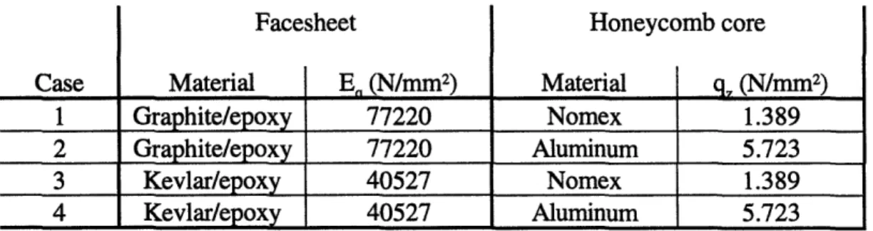
knowing the sizes of the test samples used (102 x 102 mm). Table 3 includes the
Case 1 2 3 4 Facesheet Material Graphite/epoxy Graphite/epoxy Kevlar/epoxy Kevlar/epoxy .n (N/mm 2) 77220 77220 40527 40527
Table 3: Facesheet and core combinations used
equilibrium equations and energy method.
Honeycomb core Material Nomex Aluminum Nomex Aluminum q. (NJ'Irmmn2) 1.389 5.723 1.389 5.723
to compare the results obtained using
The vertical deflection values obtained by using Equation (75) for each of the cases
mentioned are shown in Figure 8.
6000 P(N) 5000 4000 3000 2000 1000 0 0 /I I I / I I I / . ,
I
.
/ .o / / ,I / /' 2 3 4 5 6 wO (mm)Figure 8: Vertical deflection versus total indentation force response for the four
combinations of facesheets laminates and honeycomb cores proposed for the comparison
of the equilibrium equations and energy method solutions.
Case 1 -- graphite/epoxy on nomex honeycomb ---- Case 2 -- graphite/epoxy on aluminum honeycomb -. - - Case 3 -- kevlar/epoxy on nomex honeycomb -... Case 4 -- kevlar/epoxy on aluminum honeycomb I ~r
4.2. FORMULATION IN RECTANGULAR COORDINATES
The sandwich structure is composed by two elastic, homogeneous, and isotropic
facesheets and a rigid-plastic honeycomb core. The plate is considered to be infinite, with
facesheet thickness h, and honeycomb thickness H as shown in Figure 9. The facesheet is
characterized by the Young's modulus E, and Poisson's ratio v. The crushing resistance of
the honeycomb is denoted q. The problem to be solved is that of the local effect of a
quasi-static punch load acting at the center of a rectangular sandwich plate when the
deflections are large compared to the thickness of the facesheets.
/ y 1
ILL
z,41
/11
/ / 111v xFigure 9: Geometry of the sandwich plate under the punch load where P is the total
indentation force.
-7--.-K
q - = r ~~~_- _. -- I _4 . _. L__ P, 011V,
4.2.1. Approximate solution by energy method
Since the equilibrium equations for this problem derived in a non-linear differential
equation that can not be solved directly, the Raleigh - Ritz method will be used to
calculate an approximate solution. This method is based in the theory of stationary
potential energy
an = 0, (76)
where
I = U-W. (77)
U is the internal strain energy due to bending moments and membrane forces and W is the work done by applied external forces. For large deflections, the internal energy will
include only the membrane term because bending moments are negligible when compared
to membrane forces = m+ Ub - U, where UM = 2| (NGC + NCy + Nyxy)dxdy. (78) (79)
U
= 1 C (E + E2+2ve£y + -(l-v)?y 2dy,
2
Y2
(80)Eh
where C = 1 2 is the extensional rigidity. Applying the third assumption that states
that the deformation of the faceplate takes place only in the vertical direction (u, v = 0)
and introducing the strain-displacement relationships, Equations (3), gives
U
=
Cll4[(
1
)
+(ay j
dxdy.
1 4 axay 1 (81)
On the other hand, W includes the work done by the total indentation load P, and
the crushing resistance of the honeycomb
W = Pwo -
qzwdxdy,
(82)where wois the deflection at the midpoint of the plate ( x = 0, y = 0).
4.2.1.1. Solution
To minimize the error resulting from the use of an approximate energy method, it
is important to choose an appropriate shape function. The exact solution derived in polar
facesheet when subjected to the punch load. This profile suggests the use of a parabolic
shape function
w = Wo[l - 1[- 2 (83)
The comparison between this selected shape function and the one calculated from
Equation (74) using equilibrium equations and polar coordinates can be seen in Figure 10
for one particular value of the load. Similar results are obtained for different loads.
r(mm)
2 3 4 5
----
- Parabolic shape
/ . Equation (83)
/.~ .-
"~~~~~~~
,Exact
shape
fun
Equation (75)
6 7
function,
ction,
Figure 10: Comparison between the exact shape function obtained from the equilibrium
equations in polar coordinates and the selected parabolic function.
0 0 0.1 0.2 0.3 0.4 0.5 w(mm) 0.6 -~~~~~~~~ I I I -1 --- - -- , --- - I -- -I I J v ,,~
P-Introducing the shape function given by Equation (83) into the expressions for the
internal strain energy given by Equation (81) and work done by external forces given by
Equation (82) results in
U
=
2 o o
cJw
E
2 [[l
1
(-212 Y - )dxdy
(84) and W = PwO -f
qwOji-0 o 2] (85)The results after integration are
188 8Cw4
U = - .20
2205 ~2
4o
W= PWo - -~ qzw0~2.
The total potential energy is calculated by adding the two terms integrated above
8Cw - PWo 4 W 2 )2(1