The Development of a Hematology Unit:
A Case Study in the New Products Program Design Methodology by
John Kevin Sieh
B.S. Massachusetts Institute of Technology (1992)
Submitted to the Department of Mechanical Engineering in Partial Fulfillment of the Requirements for the Degree of
MASTER OF SCIENCE in Mechanical Engineering
at the
Massachusetts Institute of Technology May 1994
© 1994 Massachusetts Institute of Technology All Rights Reserved
Signature of Author
Department of Mechanical Engineering May 6, 1994
Certified by
Pappalardo Professor of Mechanical Engineering Thesis Supervisor
Accepted by
Chairman, Departgrental
Eng.
Professor Ain A. Sonin Committ • iate Studies
'Z E
Iv
The Development of a Hematology Unit:
A Case Study in the New Products Program Design Methodology by
John Kevin Sieh
Submitted to the Department of Mechanical Engineering on May 6, 1994 in Partial Fulfillment of the Requirements for the
Degree of Master of Science in Mechanical Engineering
Abstract
The New Products Program (NPP) is a new program at the Massachusetts Institute of Technology (MIT) linking academia and industry for mutual
benefit. A company sponsors a team of MIT students and faculty to design and develop a working prototype of a new commercial product. This relationship results in many benefits for all parties involved.
The current design process being applied by the NPP product development team is basic concurrent engineering, including the use of a multifunctional team and Quality Function Deployment (QFD).
The design methodology currently being used by the NPP is thoroughly
analyzed, based on one of the NPP projects, the development of a commercial hematology unit for Becton-Dickinson and Company. The strengths and
weaknesses of the design process are emphasized. Suggestions for an improved project organization and design process are given. These suggestions are based on other documented experiences and literature on design methodology.
Detailed attention is focused on the design phase of the Becton-Dickinson project.
Thesis Supervisor: Professor Woodie C. Flowers
Title: Pappalardo Professor of Mechanical Engineering Director, New Products Program
Acknowledgments
I would like offer my sincere thanks to the following people for their help and support throughout my life and most especially, throughout my involvement with the Becton-Dickinson project:
First and foremost, to my parents, without whom I could have never even been. To them I owe everything, always.
To my brothers and sister who have always shown me the way and paved it for me. My accomplishments are fruit of your work and constant example.
To the Becton-Dickinson team, Amy Battles, Shin-John Choi, Laura Edwards Mendyke, Ben Linder, Dave Otten, Brad Thomas, and Erik Vaaler. In
particular, I would like to thank Andres Pieczanski for the friendship and fun that made the project ever more enjoyable.
To Woodie Flowers who has always given me the support and expertise I needed.
To Harry West for giving me support, advice, and acknowledgment. There is nothing more rewarding than being acknowledged for one's work.
To my roommates, Hana, Paul, and Henrik who tolerated me throughout many tough times.
To Melanie, who has always been patiently there for me, listening, supporting, and sharing all my joy, sadness, failures, accomplishments, boredom and excitement.
Table of Contents
L ist of F igures ... ... 6...
L ist of T ables... 7
Chapter 1. Introduction ... ... 8
Section 1.1 -The New Products Program ... 11
Section 1.1.1. -The Organization and Strategy of the NPP... 13
Section 1.2 -The Becton-Dickinson Project ... 14
Section 1.3 -The QBC technology ... ... 15
Section 1.4 -The Walkaway ... 17
Chapter 2. The Design Process of the Becton-Dickinson Project... 22
Section 2.1- The First Prototype, a Brief Summary... 22
Section 2.2- The Alpha Prototype the Design Process ... 25
Section 2.2.1- The Design Process of the Transport System...28
Section 2.2.2- The Optics System ... ... 38
Section 2.2.3- Integration of the Alpha Prototype ... 42
Chapter 3. A Critical Review of the Becton-Dickinson Project ... 44
Section 3.1- Project Organization ... ... 45
Section 3.2- The Design Process ... ... 48
Chapter 4. An Improved Project Organization for the New Products P rogram ... ... 6 1 Section 4.1- M anagem ent...61
Section 4.2- Formation of NPP Product Development Team ... 64
Section 4.3- Creating a Good Strategy ... .... 68
Chapter 5- An Improved Design Process for the New Product Program...72
Section 5.1-Conceptual Phase... ... 75
Section 5.2- Design phase... ... 85
Appendix A- The Alpha Prototype CPM...90
Appendix B- QBC Walkaway System Design Specifications ... 93
List of Figures
Figure 1.0. The PD CA Cycle ... 10
Figure 1.1. Funding the G ap ... 12
Figure 1.2. Centrifuged Blood Tube...16
Figure 1.3. The Vac-Q-Tubes and Capillary Tubes With and Without F lags. ... 18
Figure 1.4. The Carousel in the Load/Spin Station... .... 18
Figure 1.5. The Carousel in the Reading Station and Arm Getting Tube... 19
Figure 1.6. The Walkaway Alpha Prototype ... ... 20
Figure 2.1 The First Prototype... 23
Figure 2.2 Main Concepts for Transport System... .... 29
Figure 2.3 Schematic of the Transport System Motion...31
Figure 2.4. Links of the Transport System for the Alpha Prototype ... 32
Figure 2.5. Structure of the Transport System for the Alpha Prototype...33
Figure 2.6. Cam and Cam Follower used as Driving Mechanism for the Transport System and Arm in the Alpha Prototype: Front Side ... 36
Figure 2.7. Cam Driving Mechanism of the Transport System and Arm in the Alpha Prototype: Back Side ... 37
Figure 2.8. Main Components of the Optic System...39
Figure 2.9. Structure of the Optics System for the Alpha Prototype ... 42
Figure 2.10. Structure of the Optics System for the Alpha Prototype w ith O ptical C om ponents...42
Figure 2.11. The Alpha Prototype Centrifuge, Transport, Tube Handling, and Optics Subsystems Integrated... 43
Figure 3.1. Cost of Design Changes in Each Development Phase ... 58
Figure 4.1. Effect of Top Management Support on New Product S u ccess...6 3 Figure 4.2. Impact of Early Product/Project Definition on New Product S u ccess... ... 6 9 Figure 5.1. Development of Design Specifications... 81
List of Tables
Table 1.1 -The Core Team for the First Prototype... .... 15
Table 1.2 -The Core Team for the Alpha Prototype... 15
Table 2.1 Responsibilities of each Team Member for the Alpha P rototyp e ... ... 2 7 Table 2.2. Properties of GE Noryl HM3020 and Delrin ... 34
Table 3.1. Control Factors, Problems, and Improvements ... 56
Table 4.1. Effective Product Leaders ... 65
Table 4.2. Ten Principles of Successful Teams ... 66
Table 4.3. Early Warning Signs of Problems with PDT Performance ... 67
Table 5.1 Obstacles to Successful New Product Development ... 74
Chapter 1. Introduction
"Wisdom is the ability of the brain to accept useful information, learn from it and act intelligently on it."
-Dudley Lynch and Paul Kordis
In this thesis I analyze the New Products Program (NPP) development process for a new products based on my experience with the Becton-Dickinson
project in developing a blood analyzer. After the completion of a project, members of a product development team meet with the various people from the different departments that were involved with the project and analyze the problems and successes of the project. In this manner, the same mistakes can be avoided and the successful techniques can be repeated in the next projects. This critical and very constructive analysis is sometimes referred to as a post-mortem.
The main idea behind a post-mortem is that everyone should learn from their own and other people's successes or mistakes. The post-mortem is a continuous improvement technique which identifies the errors, delays,
mismanagement, and all other problems as well as the successes associated with the project and tries to determine their root causes. Then, the review team attempts to implement solutions to the problems so that a great
majority of them will not be repeated in subsequent development projects. The post-mortem is the search of useful information and the application of that information for future benefit. This thesis is a post-mortem of the New Products Program- Becton-Dickinson project.
Examples of the benefits reaped by post-mortems are numerous. At IBM, after the main problems are identified, a database is produced that
contains the problems that were faced by a particular project and the solutions to those problems. The database can be easily accessed by merely typing keywords into a computer. Such action has reduced error by half while in other projects it sped the schedule by 16 weeks. At Motorola, there has been seven-figure savings due to the implementation of post-mortem after one project. And at Xerox, this activity is so important it is called a presidential review since even the president becomes personally involved (Zangwill, 1993).
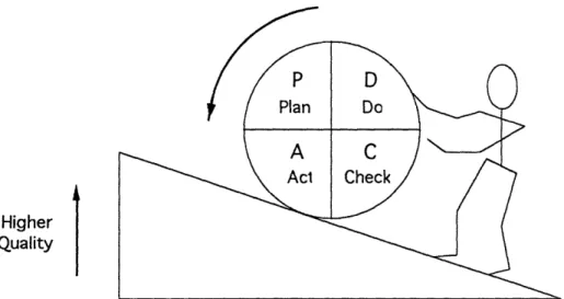
A post-mortem may take many forms. It can be an iterative process of improvement similar to the PDCA cycle of Total Quality Management (TQM).
PDCA is an acronym for Plan, Do, Check, and Act. It was first introduced into the Japanese Industry by W.E. Deming. Plan is the determination and
identification of the key problems with the current process or activities. Do is the implementation of the plan. Check confirms that the plan will improve the current process or activity. Act applies the specific changes necessary for improvement, then documents and applies the new improved process or activity (Shiba et al, 1993). The application of the PDCA cycle leads to higher quality, it is improvement in an incremental fashion (see Figure 1.0).
It is important to note that the knowledge gained from a thorough review of a project can be best applied at the beginning of a new project. Formal reviews should be held at the kick-off of a new project to familiarize with the potential problems that might arise, and to implement the solutions to those problems. These are the check and act stages of PDCA.
A newly-formed NPP team could find it useful to read and discuss this thesis. Since every team in the NPP is new for each project, the team
members have no knowledge gained from previous experience in such a program. The only sources of information for the new team members are the previous NPP students and professors, and the theses written by these students. As of today, no thesis other than this one concentrates on a post-mortem of a New Products Program project. The information in this thesis could be extremely useful and serve as guidelines to avoid errors and repeat successes in the design and development of a product in the next NPP project.
Higher Quality
Figure 1.0. The PDCA Cycle (Shiba et al, 1993)
The most important characteristic in identifying a problem to improve it is weakness orientation. Weakness orientation is an outlook into a problem with intent of searching for its root causes. On the other hand, strength orientation does not identify the problems. Instead it improves on the
performance achieved through the previous process. Improvement in this case can be limited by the capacity of the process itself and the best solution might never be reached. This thesis will use both the weakness and strength
orientation approach. It will be governed by the following characteristics: * an objective approach: a search for facts and not opinions;
* an analysis of the process and not the result; the result is merely the effect of the process; good results will be used as identification of possible strengths in the process and poor results will be used to identify weakness in the process;
* and, a search for root causes followed by suggestions of solutions for improvement; the root causes must be determined before trying to determine solutions for improvement. In this manner no problems are skipped without being first analyzed.
This thesis is more than a documentation of my work in the NPP-Becton-Dickinson project. It is the documentation of my work in light of the successes and failures throughout the project, such that, future NPP projects can learn from this experience and further improve its product development process. In Chapter 3, I critically review some of the design process steps in
the Becton-Dickinson project. Many of these steps had a strong impact on the outcome of Walkaway, and in future NPP projects, these steps can be imitated or improved for even greater success. Particular attention should be given to Chapters 4 and 5 where I propose improvements to the NPP design process, based on my experience in the Becton-Dickinson project.
Section 1.1 -The New Products Program
The New Products Program (NPP) was recently created at
Massachusetts Institute of Technology (MIT) in an effort to link academia and industry for a mutual benefit. The NPP, as its name suggests, agrees to design and develop a new commercial product for a sponsoring company. The project typically has a duration of two years, but may vary from project to project. The cost to the sponsoring company is typically $500,000, but also changes according to the magnitude, nature, and duration of the particular project.
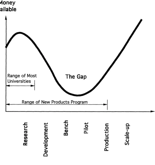
In the U.S. there is a gap between basic research and scaled production (Preston, 1993). The NPP bridges this gap by providing the necessary efforts in transferring basic technologies into commercial products (see Figure 1.1). The NPP extends the range of MIT activities beyond just technology development and include both bench and pilot phases.
The benefits to the NPP members and the company are many. The group of students and professors involved in such a program experience a real-world application of design and development. They become very familiar with the design process and the many aspects involved in developing a commercial product. This practical experience is complimentary to the theoretical
knowledge the students acquire in the classroom. Many other experiences in a NPP project, such as leadership and team work, are not taught in a classroom, and becomes extremely invaluable to the students. Moreover, the money given to fund the project also helps pay for the students' tuition and stipend. With the high cost of tuition and living expenses at MIT, and the limited amount of
research and teaching assistant positions available, the NPP gives many students an opportunity to attend MIT at no cost.
Money
Available
Range of Most
The Gap
r4-t-. .- U 0 C:£o 0 Cu V aO
-E
U (n 0O. . 0 1. L. 0)IFigure 1.1. Funding the Gap (Preston, 1993)
The benefits for the sponsoring company are just as numerous. The company receives a working prototype for a relatively small cost and in a short time. Typically, in a large company, the cycle time for the development of a new product range from 3 to 6 years. The NPP delivers in 2 years. Also, the
cost to most companies for the development of a new product is over $2 million. The company also taps into a large resource of information and state-of-the-art technology. When faced with a problem, students in the NPP team can ask other MIT professors for guidance. These students usually get this
"consulting time" at no cost to the company. All this translates into benefits to the company. In a broader scope, the NPP generates leaders in product
Section 1.1.1. - The Organization and Strategy of the NPP
The organization of a NPP project begins with a team leader, usually a MIT professor. To aid the students in the different fields throughout the project, a few professors are also hired as part of the team. These can include
professors in Electrical Engineering, Computer Science, Marketing,
Mechanical engineering or other fields depending on the project. The core of the NPP team comprises of a group of Masters and Ph.D. level graduate students, ranging in number from 3 to 5, and a couple undergraduate students. This core team is composed of students in different fields, all of which are important to the development of the new product. The number of members in the team may vary depending on the complexity of the project.
The students and professors are hired in a part-time basis, as they have to balance work and academics. Each student is expected to work 20 hours per week in the project. For professors, this amount of time is smaller since their participation in the project is not as intense in a daily basis. However, as could be expected, the students in the project spend more time in the project. It is important to note that many companies have a cycle time of 3 or more years with full-time employees working on a project. The NPP only has students working part-time, which extrapolating into full-time hours the NPP cycle time is just over one year.
The design process utilized in the NPP is basic concurrent engineering. Basic concurrent engineering is a significant improvement in game plan and teamwork relative to the traditional serial design process. The better game plan is the concurrent process, reinforced by emphasis on quality, cost,
delivery, and customer satisfaction. This emphasis is achieved through the use of Quality Function Deployment (QFD). Better teamwork comes from the use of a multifunctional team.
As stated above, the NPP was not created only to produce a working prototype for a company. The NPP is also a learning experience for all those involved, especially the students. Although the students agree to design and develop a product, it is not fair to demand that the students perform a perfect job, particularly in regards to following a design process. To most students involved in the NPP, the project is their first real-world experience with the
classes at MIT attempt to simulate the process related to product
development, most of these attempts are never able to imitate a real product development project in its entirety. In this thesis, although I point out many imperfections in the design process of the Becton-Dickinson project, my intentions are not to criticize the work done in this project, but to emphasize the areas that can be improved for future NPP projects.
Section 1.2 - The Becton-Dickinson Project
Together with another project, the Becton-Dickinson project was the first NPP venture. The Primary Care Diagnostics division of Becton-Dickinson and Company sponsored a NPP project to develop the Walkaway, a fully automated blood analyzer based on the Quantitative Buffy Coat (QBC)
technology. The project comprised of two phases including: a conceptual phase where the product development team did market studies and concept
generation, and determined the final concept of the Walkaway; and a design phase where the concept for the Walkaway was transformed into layout
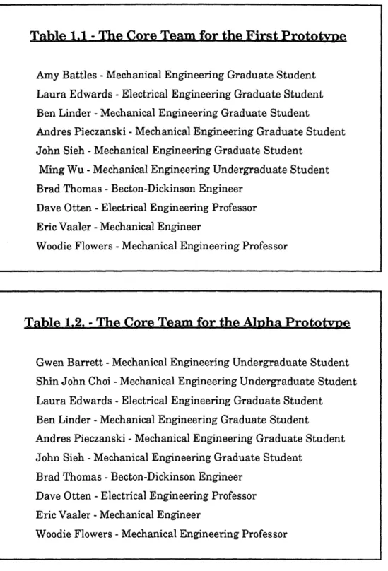
drawings and into an alpha prototype. My involvement with the Becton-Dickinson project began with the design phase and this thesis will concentrate (but not limit itself) in analyzing the strengths and weaknesses within that phase. Table 1.1 and 1.2 lists the core team for each phase of the Becton-Dickinson project.
The design phase of the Becton-Dickinson project can be divided into two segments: first prototype and alpha prototype. The first prototype aimed at testing the functionality of all the subsystems and showing its overall
functional layout. The alpha prototype aimed at not only showing all the
functions of the Walkaway, but also demonstrating the true components of the machine, including final concept, shape and layout. Although the first
prototype did not resemble much of a commercial product, it was a very important prototype for the product development team (PDT). It finally put the many subsystems together to form a blood analyzer, the Walkaway. This visual and functional "tool" was a foundation on which a better prototype could be built.
Table 1.1 -The Core Team for the First Prototype
Amy Battles -Mechanical Engineering Graduate Student
Laura Edwards -Electrical Engineering Graduate Student
Ben Linder -Mechanical Engineering Graduate Student
Andres Pieczanski -Mechanical Engineering Graduate Student
John Sieh -Mechanical Engineering Graduate Student
Ming Wu -Mechanical Engineering Undergraduate Student
Brad Thomas - Becton-Dickinson Engineer
Dave Otten -Electrical Engineering Professor
Eric Vaaler -Mechanical Engineer
Woodie Flowers -Mechanical Engineering Professor
Table 1.2. - The Core Team for the Alpha Prototype
Gwen Barrett -Mechanical Engineering Undergraduate Student
Shin John Choi -Mechanical Engineering Undergraduate Student
Laura Edwards - Electrical Engineering Graduate Student
Ben Linder -Mechanical Engineering Graduate Student
Andres Pieczanski -Mechanical Engineering Graduate Student
John Sieh -Mechanical Engineering Graduate Student
Brad Thomas -Becton-Dickinson Engineer
Dave Otten -Electrical Engineering Professor
Eric Vaaler -Mechanical Engineer
Woodie Flowers -Mechanical Engineering Professor
Section 1.3 -The QBC technology
The QBC method (Levine and Wardlaw, 1988) of hematology, the
in a small tube coated with reagents. The centrifugation separates the blood into distinct bands (according to density) and each band represents different blood cell types. The blood cell types can be divided into two main categories: red blood cells and white blood cells (WBC) or Leukocytes. The WBC are further divided into two categories: Granulocytes and Non-Granulocytes. By reading the lengths of each band, and knowing the diameter of the tube, the cell counts for each type can be calculated. After centrifugation, the blood is
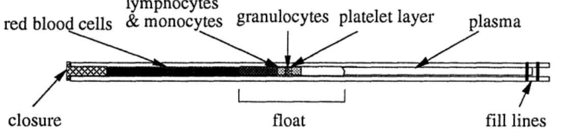
separated into plasma, WBC and red blood cells (see Figure 1.2). The WBC region is also known as the buffy coat. The volume of WBC is small compared to that of the RBC; thus, a plastic float with the same density of the WBC is inserted in the tube prior to centrifugation, expanding the buffy coat region 10 times as it separates.
lymphocytes
red blood cells & monocytes granulocytes platelet layer plasma
closure float fill lines
Figure 1.2. Centrifuged Blood Tube (Battles, 1993)
The different blood layers, when mixed with the reagents, contain
different colors. For example, the granulocytes fluoresce yellow while the non-granulocytes fluoresce green. Two tests are currently performed in the tube: transmission and fluorescence. For fluorescence readings, a blue excitation light is focused on the tube at 90 degrees from the optical reading. The transmitted light passes through color filters before the optical sensor and allows the sensor to detect the light intensity at each small axial increment along the tube, thus determining the band widths. For the transmission
reading, a white light is transmitted through the tube and with the appropriate filters, the different blood bands can be determined. The fluorescence test is done 8 times around the tube. These readings around the tube are averaged for
There are many glass tubes used for blood analysis. In regards to the Walkaway requirements, there are two main types of tubes it should be able to read: Vac-Q-Tubes and capillary tubes. There are many types of capillary tubes, filled with different reagents, and these tubes are used to perform different blood tests. One such tube is shown in Figure 1.2. However, they all have the same physical dimensions: 0.09" in diameter and 3.00" long. The Vac-Q-Tube, which the Walkaway also had to be able to read, has dimensions of 0.21" in diameter and 2.74" in length.
Section 1.4 -The Walkaway
Through a thorough marketing study, the Walkaway's functional requirements were determined. Besides performing the QBC analysis, some requirements included: testing capacity for multiple tubes, reading and accommodating capillary and Vac-Q-tube tubes, and patient identification in each tube. Patient identification is a sticker with a bar code used to identify the patient. Since capillary tubes are small in diameter, it would not be feasible to attach a sticker to the tube. Thus, a plastic flag was designed to be attached to the tube without obstructing the view of the blood inside. The bar code sticker is attached to the flag. A flag was designed for both capillary tubes and Vac-Q-Tubes. Both tubes are shown with and without flags in Figure 1.3.
After a tube is filled with blood, it is put on a carousel. There are two types of carousel in the Walkaway. One that accommodates capillary tubes and another for Vac-Q-Tubes. Each carousel accommodates up to ten tubes. The carousel is then placed inside the rotor, which holds the carousel. The rotor must be in the load/spin station when the carousel is placed in it. This station differentiates from the read station which is where the tubes are read after being centrifuged. Figure 1.4 shows the carousel in the rotor and positioned in the load/spin station.
Figure 1.3. The Vac-Q-Tubes and Capillary Tubes With and Without Flags
Figure 1.4. The Carousel in the Load/Spin Station
Once the carousel is in the rotor, the lid of the Walkaway is closed so there is no more user access to the tubes until all tests are completed. Before centrifugation, a cover is engaged to seal the carousel inside the rotor and hold the tubes on the carousel. After centrifugation, the cover is disengaged and the carousel with tubes are moved to the read station where the tubes are read. One tube is picked up from the carousel by the arm, which places it in the indexer. The transport driving mechanism which moves the carousel from the load/spin station to the read station also moves the arm. Figure 1.5 shows the carousel in the reading station and the arm being actuated by the transport driving mechanism to get a tube from the carousel.
Figure 1.5. The Carousel in the Read Station
and Arm Getting Tube
The indexer holds the tube while fluorescence and transmission tests are performed on that tube. As mentioned above, 8 readings are taken around the tube length and an average of the 8 readings is used for the final hematology result. The indexer rotates the tube to the 8 positions. The optics system reads
the tubes and the bar code sticker attached to the tube via the flag. It is important that the optics system be precise when reading the different layers of blood formed in the tube. The arm puts the tube back to the carousel and another tube in the carousel is read. The sequencer rotates the carousel so the arm can pick-up the next tube. After all tubes in the carousel are read, the carousel is moved back to the load/spin position. Then, the lid can be opened and the tubes can be removed from the carousel.
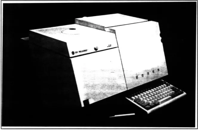
The Walkaway alpha prototype was completed in November 23, 1993 and is shown in Figure 1.6.
Figure 1.6. The Walkaway Alpha Prototype
The Walkaway can be divided into the following subsystems and functions:
Centrifuge subsystem comprises of the centrifuge which spins the tubes, the carousel which holds the tubes, and the cover which holds the tubes in the carousel and seals the system.
Transport subsystem moves the tubes from the load/spin station to the read station, actuates the arm, and engages the cover.
Optics subsystem: performs both fluorescence and transmission tests, including reading the tube and bar code for patient identification.
Tube handling subsystem: picks-up and returns the tubes from the carousel, and indexes the tubes in 8 positions.
Controls and Software includes all supporting equipment to run the Walkaway including all electronic equipment.
Industrial Design includes machine layout, exterior look and customer interface.
Patient Indentification includes flag and bar code.
Sequencing rotates the carousel from tube to tube for the arm to pick-up and return all tubes in the carousel.
These subsystems will be described in greater detail in the next chapter. Particular attention will be given to the Transport and Optics subsystems which was the core of my work in the Becton-Dickinson project.
Chapter 2. The Design Process of the
Becton-Dickinson Project
My involvement with the Becton-Dickinson project began at the late stages of the first prototype and I will concentrate in describing and
documenting my experience starting at that point. However, to fully understand what happened before this stage and the many decisions and actions taken during the conceptual phase of the project, one must read the theses written by Don Lee (Lee, 1993) and Amy Battles (Battles, 1993), which document that phase. In the subsequent chapters, I will mention some
improvements in that phase although I did not participate in them. My observations are based on my experience working with the results generated during the earlier phases.
Section 2.1- The First Prototype, a Brief Summary
My main responsibility in the first prototype was to make a structure for the tube handling subsystem and some optics components. These included indexer and arm, and two fiber optic bundles used for transmission and
fluorescence tests. It was necessary to obtain all requirements for the position of each component and design the structure for these components. Integrating the many subsystems was a difficult task. Being new to the project and not having the background information on the design of the total system, it was laborious to obtain and understand the necessary information for the design of the mounts for each component. Given the short time left before the
urgent need to have a structure integrating the many subsystems, the structure was over-designed. Some examples include excessive number of screws and large thickness of the aluminum plates used for the structure. The final size and shape of the first prototype was large and did not resemble a commercial product. The optic bundle, for example, had to be mounted approximately 18 inches from the table surface, an amount beyond the design specification for the Walkaway. The structure also had to be out of the path of the transport system, thus forcing the indexer and fiber optic bundle to be mounted on a cantilevered bar, away from its base. Although the first prototype did not meet many of the customer requirements specified during market study, the need of having an integrated machine was more urgent. For the first time, the subsystems which students were individually working on were integrated to form the first Walkaway prototype. This step was crucial to finalize the overall concept, functions, and layout of the blood analyzer. The presentation of the first prototype was held on May 23, 1993 at MIT. The prototype is shown in Figure 2.1.
The Centrifuge System
Due to the complexity of the centrifuge system and the lack of time, not all components in this subsystem were operational for the presentation. The centrifuge was not tested before or during the presentation since it did not have a blast shield to protect against a possible failure during centrifugation.
Therefore, other components that were dependent on the functionality of the centrifuge were also not tested. These included the seals of the rotor, the tube behavior in the carousel, the functionality of the cover, and spinning to a speed of 11,500 rpm. Not being able to spin the centrifuge prevented the test of
possible mechanical failures associated with the system, including the strength of the shaft of the centrifuge motor, strength of the transport system,
vibration, and noise level. However, all components of the centrifuge system were represented in the prototype, including a mock-up blast shield. Having all components in this subsystem was important to finalize all of the centrifuge system's functions and the necessary components to achieve those functions.
The Transport System
The transport system fulfilled all its functions: to move from load/spin to read position, to engage the cover to the rotor, to actuate the arm, and to
sequence the carousel. The transport was chosen under the criteria of flexibility and feasibility. These criteria were deemed most important for the first prototype. Other customer criteria generated in the House of Quality were purposefully neglected. Though the transport system was very successful in the first prototype, it would have to be modified to meet the customer
requirements necessary for a final production model.
Tube Handling
The indexer was able to hold capillary tubes and index them reliably. The only functional requirement for the indexer which was not implemented in the first prototype, was being able to index Vac-Q-tubes. Given the robust
performance of the indexer, its concept did not change much for the alpha prototype, even with the new function of handling Vac-Q-tubes.
The arm was also successful in reliably picking capillary tubes from the carousel. However it was not able to put them back on the carousel or dispose them in another manner. Disposal of the tubes was a function introduced late in the fabrication of the first prototype and it was dismissed for the first
prototype. Thus, for the alpha prototype, given these new requirements, tube disposal and handling Vac-Q-Tubes, the arm underwent many changes in its design.
The Optics System
The optics system showed good performance. Though the resolution of the tube onto the Charged Coupled Device (CCD) was below acceptable
conditions, it was clear that with better optical components the blood tube could reach the desired resolution. The CCD, the Walkaway's fundamental technology in tube reading, showed great performance. The research and tests done in the earlier phases of the project proved to very beneficial. To improve the resolution of the tube, new optical components would have to be selected including a better lens and changing the circular variable filter for a linear one. A circular variable filter was used for the first prototype since it was
commercially available.
The Sequencer
The concept chosen for the sequencer was heavily influenced by the concept chosen for the transport system. To reduce the number of actuators in the prototype, the sequencer was integrated with the transport mechanism. The sequencer concept worked well and was very feasible for the first
prototype. However, the need to change the transport system for the alpha prototype led the sequencer to undergo another design iteration, starting from concept generation and selection.
Section 2.2- The Alpha Prototype: the Design Process of Two Subsystems
After the completion of the first prototype, the next and last step in the Becton Dickinson project was to produce an alpha prototype of the Walkaway. The entire team and representatives from Becton-Dickinson discussed the definition of an "alpha prototype" and what should be expected from the Walkaway alpha prototype. An alpha prototype is a working model of the
machine. It differs from a final production prototype in that many of its components are not manufactured using the same processes. For example,
instead of having injection-molded parts, an alpha prototype contains
machined parts that have the same shape as the production ones. Preferably, the material is also the same. After some discussion, it was determined that the alpha prototype for the Walkaway would not contain a PC board within its shell. Instead, the proper packaging would be allocated for this board and all other components not included inside the shell. The components and main subsystems of the prototype would be as similar to a production unit as possible.
After determining our goals for the last phase of the project, we made a plan for the final stage of the project. I was responsible for that task and used a Critical Path Method (CPM) as the planning tool. The original CPM was based on the design process for precision machine design. It is important to note that the design process for a precision machine design is different from that of a new consumer product. The CPM estimated a time for the completion of the alpha prototype that was longer than the time we had left until the end of the project. The CPM estimated about eight months time for the completion of the project; however, the last day in the MIT NPP contract, was November 3, leaving about 5 months for the completion of the project .Aware of the limited time left, we compressed and eliminated some of the activities in the CPM so it would fit into the schedule. We decided to take on the challenge of completing the alpha prototype even knowing that the time allocated was much less than ideal.
The CPM contained the major tasks necessary to build the prototype, however, it did not include any details on the process to be followed. There were no references to tools or methods for performing any of the design. The final CPM can be found in Appendix A.
The first task in the plan was to do all appropriate tests with the first prototype. Since the centrifuge was not spun due to the lack of a blast shield, we built a shield out of concrete and tested the centrifuge. We learned that despite some imbalance in the rotor, at about 12,000 rpm the imbalance had no consequences. We also learned that with the cover, the centrifuge was very noisy. The tests also allowed us to find out more about the driver board being used to control the centrifuge. The driver board used was manufactured by Becton-Dickinson and is used in their commercial centrifuges. However, because the centrifuge would undergo many design changes to fulfill the customer requirements, we decided not to perform any more tests. This was
the case for all other subsystems. It was clear that the alpha prototype would be very different and spending more time studying the first prototype would not be productive.
The first step taken in the design of the alpha prototype was to assign the different subsystems to the members of the product development team (PDT). The main subsystems were separated into: optics, transport,
centrifuge, arm, sequencing, electronics and software. The subsystems were assigned according to each student's knowledge and experience about that system. Two new undergraduate students joined the PDT, Gwen Barrett and Shin-John Choi, both mechanical engineers. The responsibilities of each student are shown in Table 2.1.
Information on the design specifications of the Walkaway generated in the previous phases was gathered in a single document. This document was reviewed by all members of the PDT as means of familiarizing the team with the necessary specifications of their design. The final specification list can be found in Appendix B.
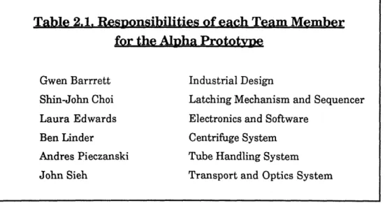
Table 2.1. Responsibilities of each Team Member for the Alpha Prototvye
Gwen Barrrett Industrial Design
Shin-John Choi Latching Mechanism and Sequencer
Laura Edwards Electronics and Software
Ben Linder Centrifuge System
Andres Pieczanski Tube Handling System
Section 2.2.1- The Design Process of the Transport System
The first prototype was very useful as a tool to illustrate the concept and the main functions of the Walkaway as one integrated machine. However, the details of the total system layout and its subsystems were vague. The first prototype lacked some required functions, such as supporting Vac-Q-Tubes, and returning tubes to the carousel. Moreover, the first prototype did not meet some of the design specification generated in the conceptual phase. It was clear that, though the first prototype was extremely useful and a necessary step in the design process of the Walkaway, there was a need for improvement. The main concepts for the Walkaway remained the same, but there was room for complete redesign within those boundaries. For example, the details of the concept for the transport system were the functions it had to perform. The main criterion for choosing a transport system with two linear motions in the first prototype was the flexibility it could offer. The criteria for the transport system in the alpha prototype would have to be completely different. Flexibility would not be needed in the final product, yet many other characteristics would, especially low cost. Thus, a new concept selection process had to be started for the transport system. In this concept selection process, the customer criteria would be used to select the new transport. Like most other members of the team, I started my systems from concept generation and selection.
The concept generation and selection process for the transport system began with clarifying the functions it had to perform:
* bring the carousel from the load/spin station to the read station, * and, engage and disengage the cover.
A decision had to be made as to whether the mechanism moving the transport system should also drive the arm. This was a variable introduced in the
concept selection.
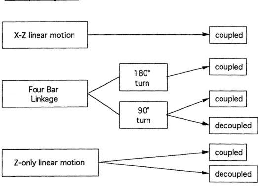
Given the functions necessary for the transport system, four main concepts were studied: a rotary motion with a 900 travel, a rotary motion with
1800 travel, a two axis motion (vertical and horizontal travel), and a one axis motion (only vertical travel). For every main concept, the arm had the option of being independently actuated or coupled to the transport mechanism. See Figure 2.2.
Arm Motion
Transport System
X-Z linear motion
Z-only linear motion
S coupled
coupled decoupled
Figure 2.2. Main Concepts for Transport System
The criteria I used for selecting the transport system were determined by what I thought would be important characteristics in the transport system. The main criteria for the selection were:
* material costs
* use of standard parts * robustness/reliability * accuracy * assembly * integration * footprint * labor costs * manufacturability * vibration/noise isolation * number of parts
I used an Analytical Hierarchy Process (AHP) as a tool to select the best transport concept given the criteria above. Before conducting the AHP ( for more detail, read Saaty, 1980 and Slocum, 1992), the six concepts for the transport system were detailed. They were broken down into main components and a cost was estimated for its parts. The rotary motion was a four-bar-linkage and the linear motions were sliding tables actuated by linear screws. Because the rotary concepts were new, while the linear concept was used in the first prototype, some CAD simulation and two mockups were built to
better understand the rotary concept. Even before building mockups, some foam core pieces were used to study the path of the links and their possible collision. With the information from the mockups and the simulations, it was clear that the rotary motion with 900 would generate a more compact
machine. However, the 1800 motion would make coupling the arm simpler. It would be similar to the coupling of the arm and transport designed in the first prototype. At the time there was little information on sequencing and whether the transport system would include actuating the sequencer. If the sequencer was to be kept similar to that of the first prototype, both of the rotary
concepts would not have difficulty incorporating that type of sequencing. The results of the AHP indicated that the rotary motion with a coupled arm was the best concept. The criteria that had the most impact on the decision was the cost. The rotary motion with a coupled arm had the least amount of actuators. The number of actuators was determined to drive the cost of the subsystem. Thus, the concepts with extra actuators were quickly eliminated, such as the two axis motion with decoupled arm and the 1800 rotary motion with de coupled arm. The one axis only concept with coupled arm, while using only one actuator, was determined to be more complex, especially in integrating it with the optic system. A schematic drawing of the final transport system motion is shown in Figure 2.4. Another advantage of the 900 rotary concept was its compactness.
One of the concerns with the chosen concept was its driving mechanism. The load it would have to support due to the weight of the centrifuge system was large. One solution to the problem was to counterbalance the weight of the centrifuge.
With a transport system concept chosen, I began working on its main components. I built a transport system prototype, this time trying to
represent what I envisioned as the final subsystem. I built the prototype trying to minimize its size while still maintaining the functions it needed to perform. The material used for the transport prototype was aluminum. The prototype was extremely useful. It allowed me to understand the requirements for the link connections, and the preload necessary to counterbalance the weight of the centrifuge subsystem. I noticed that torsion springs could be incorporated with the links to counterbalance the weight of the centrifuge and
cover spin station station four-bar links spin station read station rotor centrifuge motor four-bar links
Figure 2.3. Schematic of the Transport System Motion
A •
f rlvqc
relieve the load of the transport driving mechanism. Using the transport prototype as a visual aid, I also determined, roughly, the final shapes of the main components of the transport system. I also determined the
manufacturing processes and materials used to fabricate these components. Another benefit from the prototype was being able to show it to the other members of the PDT. They became aware of its concept, functionality, and size, which was now about 4 times smaller than the first prototype.
Only the back links in the transport system prototype had to be
redesigned. The back links were connected via an aluminum plate. To prevent the transport system from warping, it was necessary that the stiffness of the two back links be equal. The original plate used to transmit torque between both links was not stiff enough. Thus, the plate was moved to a new location and its thickness was doubled. With this new configuration, the two links and the plate were determined to become one bent aluminum sheet. The links and plates fabricated for the alpha prototype are shown in Figure 2.4.
The structure of the transport system was determined to be injection-molded and made out of structural foam. The decision to manufacture it this way came from the current manufacturing methods used by Becton-Dickinson for the structure of the Hemascan, a low-volume blood analyzer currently in the market. The transport structure for the alpha prototype is shown in Figure 2.5. The material used for making the alpha prototype structure was Delrin. Delrin was chosen since its properties are very similar to that of structural foam. The particular structural foam used by Becton-Dickinson for the Hemascan is GE Noryl HM3020 (high modulus grades). Table 2.2 compares the properties of these two materials.
The links and the mount for the centrifuge in the production stage were determined to be stamped and bent aluminum parts. Drilling the pivot points in the links would be the final operation due to the tolerances necessary for their position. The pivots between the links and the structure would be rivets. The bearing for the rivets were determined to be flanged, oil-impregnated bronze bushings, pressed into the links, structure, and mount plate. The flange would serve as spacers between two connecting links. All the decisions made when choosing the parts, manufacturing processes, and assembly sequence for the transport system were based on the reduction of cost.
The next step was determining the driving mechanism for the transport and the arm. In brainstorming different driving mechanism ideas, I had the option of placing the arm perpendicular or parallel to the plane of rotation of the transport system. I decided to keep the arm parallel to the rotation plane to reduce the frontal area of the machine. A small frontal area was one of the customers' criteria. Thus, the transport system was determined to rotate away from the front of the machine. However, due to space constraints for the user interface, the final configuration of the Walkaway was changed later. The transport would rotate from left to right.
Table 2.2. Properties of GE Norvl HM3020 and Delrin
GE Noryl HM3020 Delrin
PHYSICAL
Specific Gravity 1.25-1.43 1.42
Water Absorption (24 hr.) 0.06-0.07 0.25
MECHANICAL
Tensile Strength, yield (psi) 9,420-18,450 10,000
Flexural Strength, yield (psi) 16,000-22,700 14,100
Flexural Modulus (kpsi) 500-1,379 410
Hardness, Rockwell M 88-90 94
Coefficient of Friction (self) 0.04-0.42 0.3
The driving mechanism, besides having to actuate both transport and arm, also had other constraints. The driving mechanism would have to support the weight of the centrifuge system and another 10 lb force caused by a user trying to force the carousel into the rotor. The driving mechanism would also have to have enough force to engage and disengage the cover and enough force to hold the rotor fixed against aligning stops in the read station. The summary of constraints that the driving mechanism had to fulfill were as follows:
* load of at least 10 lbs at the carousel;
* enough force to engage and disengage cover; * enough force to "bottom" the carousel onto stops; * should not be backdrivable;
* and, should actuate arm and transport.
My initial concept was a simple link connected to a geared stepper motor that would drive the transport with 900 of its motion and use the remaining angle to drive the arm. This concept would fulfill all specifications except having enough force to "bottom" carousel. It would also require a non-backdrivable geared stepper motor with very high torque. The trade-off was between higher torque or higher speed. It was determined that the transport
should take at most 5 seconds to move from load/spin to read position. Given this requirement, the highest torque stepper motor available was bought and tested. The results showed that the motor was backdrivable under the
specified load.
The idea of using a cam was introduced by one of the Becton-Dickinson engineers, Brad Thomas. I investigated that concept and determined that the cam could have two profiles: one to drive the transport and one to drive the arm. The arm would be idle while the transport moves, and the transport would be idle while the arm moves. Finally, I simplified the design by having the arm preloaded in one direction and be actuated by a pin connected to the cam wheel. Thus the cam wheel would only have a profile on one side to drive the transport system and a pin on the other side to drive the arm. The pin would engage the arm when the cam follower driving the transport system reaches a constant radius and does not move. After extensive simulation using a spreadsheet trying to determine an optimum location for the cam wheel and its profile, I came to the conclusion that the cam concept could fulfill all the requirements necessary. A cam has the ability to have different gains, and I defined a profile that would have higher gains when the centrifuge is engaging/disengaging the
cover and securing in the read station. These very high gains also prevents the centrifuge from being backdrivable at the load/spin position. The driving
mechanism (cam) for the alpha prototype is shown in Figure 2.6 and Figure 2.7.
After the cam and follower configurations were determined, the stresses acting on the cam were calculated. The material selection for the cam was based on the stresses it would have to withstand. The main factors influencing stresses in cams are: radius of curvature for cam and follower, and materials.
If the calculated maximum stress were too great, it would be necessary to change the cam design. Such changes include: increasing cam size to decrease pressure angle and increase the radius of curvature; changing to an offset or swinging follower to reduce the pressure angle; reducing the cam rotation speed to reduce inertia forces; increasing the cam rise angle; increasing the thickness of the cam, provided that deflections of the follower are small enough to
maintain uniform loading across the width of the cam; and using a more suitable cam curve or modifying the cam curve at critical points, such as the loading position.
I
Figure 2.6. Cam and Cam Follower used as Driving Mechanism for the Transport System and Arm in the Alpha Prototype: Front Side
36
Figure 2.7. Cam Driving Mechanism of the Transport System and
Arm in the Alpha Prototype: Back Side
The compressive stress, Sc (psi), developed at the surface of contact between a roller follower and the cam is given by:
Sc = 0.558 Fa(1/p + 1/+2) (1)
b[(1 - gll2)/El+ (1 - 922)E21
where, Fn is the normal load (lbs); b is the width of the cam (in.); pl and P2 are the radii of curvature of the follower and cam (in.), respectively; g1 and p2 is Poisson's ratios for follower and cam, respectively; and E1 and E2 are the
moduli of elasticity of follower and cam (psi), respectively. A 10 lbs. load on the carousel, when transmitted through the links to the cam, becomes a normal load of 40 lbs, due to the ratio between the links and the follower. Given the constraints of the cam size, using equation (1), the smallest possible cam follower would have a diameter of 0.50" and a width of 0.375". In the production phase, the cam could be injection-molded out of structural foam without being
damaged. The cam profile would not be a manufacturing issue once the mold was made.
Coupling the cam to the motor for the alpha prototype was done using a split hub clamp. In the production phase, coupling would be achieved by
molding a shaped" hole in the center of the cam which would match the "D-shaped" shaft of the driving motor. This would simplify the design of the cam and reduce the number of parts.
Section 2.2.2- The Optics System
My other responsibility included the optics system. The functions that the optic system had to perform include transmission blood test, and
fluorescent blood test. The main components of the optics system are shown in Figure 2.8. The function of each component is as follows:
* the Charged Couple Device (CCD) reads the tube, * the lens focuses the tube onto the CCD,
* the variable filter filters the bands of light before being read by CCD, * the linear stepper motor moves the variable filter to different bands,
* the transmission light emits a white fluorescent light for transmission
test; the light rays are emitted on the same line of the CCD and the tube,
* the fiber optic bundle makes the light source for fluorescence test
become a strip of light with even intensity,
* the blue filter filters the fluorescent light source and makes it blue, * the cylindrical lens focuses the fluorescent light on the tube,
* and, the halogen light source is the source of light for the fluorescent
light.
The functions of the optic system were determined during the conceptual phase of the project. It was clear that the Walkaway had to perform at least the transmission and the fluorescence tests, however, it was also determined that provision should be made to accommodate future tests which have not been defined yet. This entailed using a variable filter at the source of the fluorescent light and another variable filter between CCD and
mirror
fiber optic
blue
I r_12 Ifluorescent
light
O
,
Itrce
CCD
and
board
Figure 2.8. Main Components of the Optic System (side view)
tube. With this arrangement, it would be possible that Becton-Dickinson devise new blood tests for other parameters in the future and still use the Walkaway for these new test without having to modify its hardware. The alpha prototype of the Walkaway did not provide for a variable filter at the source. It was determined in the design specifications that a variable filter at the light source would not be necessary for the prototype.
Since the fluorescence and transmission tests were successful in the first prototype, one of my main tasks in the development of the optics system for the alpha prototype stage, was selecting the optical components and their layout. A new lens, with higher resolution, was selected. The transmission light was changed from a fiber optic bundle and light source to a simple fluorescent light bulb and an inverter, thus reducing the cost from $500 to $16.
For a shorter layout of the Walkaway, the transmission fiber optic bundle was set horizontally, and a mirror was used to reflect the transmission light onto the tube.
Alignment requirements of the Optical System
The alignment requirements of the optical components are as follows: * the CCD must align with the tube;
* the lens must focus the 3 inch tube on the 2 inch CCD; * the transmission light must be aligned with the tube;
* and, the fluorescent light must be focused on the front half of the tube and must be aligned with the tube.
These alignment requirements generated a large number of adjustments in the mounting of each component to the structure. To require the
components to be aligned through tight manufacturing tolerances would increase the manufacturing costs substantially. In some cases, the supplied components already contained manufacturing imprecision that were greater than the allowable optical alignment amount. This included the CCD, whose parallelness and height varied from piece to piece and the lens whose focal length also had too much variation. Given that the axis of the indexer was fixed, i.e., the axis of the tube, the following adjustments became necessary:
* a rotation and translation of the CCD (to adjust the parallelness and height);
* a translation for the lens (to adjust focus between CCD and tube); * two rotations for the mirror (to adjust parallelness and position of the light with respect to the tube);
* translation of the cylindrical lens (to adjust focus of the fluorescent light on the tube);
* rotation and translation of the transmission light source (to adjust parallelness and height with respect to the tube).
For assembly purpose, I decided to incorporate as many optic
components possible in one structure. This would allow the optics to be pre-aligned as a sub-system. Once pre-aligned, the optics system could be integrated with the other subsystems. It also made sense to incorporate the tube handling system with the optics since the optic components and the arm mechanism have to be aligned with respect to the position of the tube. Finally, the sequencing sensors were also mounted on the optics structure since it was conveniently located.
Much thought was put in the design of the adjustment and clamping mechanisms for the optics components. They were design for easy assembly and adjustment. A clip-on clamp holds the lens and the fiber optic bundle. Both
in the production model and alpha prototype, these clamps were determined to be stamped and bent sheet metal. The adjustments for the mirror and CCD were designed to be achieved by turning two screws. The CCD had two vertical screws holding the two upper corners of the CCD board. The CCD board was placed on a spring which pre-loaded it onto the screws. By turning one screw or the other, the board would change its angle, and by turning both screws in one direction, the CCD board would travel up or down. Thus, two degrees of freedom (vertical travel and one rotation) was achieved with two screw adjustments.
As with the transport system, the structure for the optics system was determined to be injection molded structural foam. Thus, I designed a structure that would contain all the optical components (except the transmission light) and the tube handling mechanisms, arm and indexer. The optics structure is shown in Figure 2.9. The transmission light was left out of the optics structure since it was in the path of the arm and tube motion. Figure 2.10 shows the optics structure with all its components mounted, including arm, indexer, and sequencing sensors. Careful attention was spent to make the structure "injection-moldable", but due to the many components it had to support and the constraints that each component imposed on the structure, the version made for the alpha prototype cannot be injection-molded without many actuations in the mold. In order to make the optics structure easier to
injection-mold, the arm will need some redesign to accommodate the changes in the structure.
Section 2.2.3- Integration of the Alpha Prototype
At about two months before the scheduled completion of the alpha prototype, we started discussing the configuration of the machine and its
supporting components, such as keyboard, disk drive, and screen. At that late stage, the configurations of the subsystems were already determined, leaving very little room for many possible layouts of the machine. We decided to have the centrifuge on the left side and the optics on the right side, to allow enough frontal area for the screen.
Figure 2.9. Structure of the Optics System for the Alpha Prototype
V
Figure 2.10. Structure of the Optics System for the
Alpha Prototype with Optical Components
As we drew closer to the presentation date for the alpha prototype it was clear that the machine would not be ready by November 3rd and the
presentation was delayed to November 23rd. When integrating the different subsystems, many problems arose. Some subsystems were late to be completed or needed reworked. This forced the testing of the machine to be rather late and time ran out before all the problems could be fixed. Some of these include:
* the centrifuge noise and vibration level were high, * the linear variable filter had a very low transmission,
* the arm could not pick-up tubes in certain locations of the carousel, * the transmission light did not have proper alignment,
* and, the centrifuge motor had large cogging forces and would not allow for sequencing.
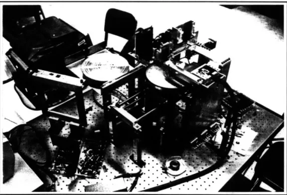
Figure 2.11. The Alpha Prototype Centrifuge, Transport,
Tube Handling, and Optics Subsystems Integrated
Chapter 3. A Critical Review of the
Becton-Dickinson Project
In this chapter, the Becton-Dickinson project is critically analyzed. The reader must note that despite the many problems described in this chapter, the success of the Becton-Dickinson project is unquestionable. Since the completion of the project, the Walkaway alpha prototype has been shown to various Becton-Dickinson representatives in Europe and United States and has gained much approval. Rudy Rodriguez, Vice President of Research and Development of Becton-Dickinson Primary Care Diagnostics division, wrote: "I believe this program was a good investment for Becton-Dickinson and a net win-win for both organizations. Would I do it again? Yes, absolutely."
For equal success, future NPP projects could imitate the design process followed in the Becton-Dickinson project. The most successful activities are emphasized in this chapter to solidify the winning actions in the current NPP design process. However, not all projects are completely perfect, and the Becton-Dickinson project has also had its obstacles. These obstacles are also described below. For even greater success, future NPP projects should avoid committing the same mistakes. A description of an improved project
Section 3.1- Project Organization Project management
The intention of the NPP is not to have one aggressive leader in control of the entire project. It focuses on having every member of the product
development team (PDT) taking some responsibility in leading the project. The management and leadership experience gained by the students in the project is invaluable. However, it is important to have one person in charge of overseeing
the entire project, a person responsible for facilitating and administering it. That person is the project leader.
The leadership in the Becton-Dickinson project suffered an unavoidable change in the middle of its development. This change violated one of the points for effective leadership: "the leader has responsibility that endures over the entire duration of the development program" (Clausing, 1993). Although having the leader remain in the project throughout its duration is a crucial need, it is practically impossible to enforce it. It is very important that future project leaders in the NPP be professors who have a low probability of leaving the job.
If a project leader decides to leave the project, provision should be taken that a new leader be assigned to the project while the old leader is still present. This
overlap will allow the new leader to update himself/herself to the project while the old leader is still in charge. Thus, when the original leader leaves, the new leader can take an active role immediately.
Due to the limited resources in the NPP, the time a leader allocates to the project is very limited. In the Becton-Dickinson project, the little time spent on the project by both its leaders, led them to lack some of the important points for effective product leaders. These include:
* taking an active role in managing conflict and preventing problems with the team performance, exemplified by the initial conflicts between team members, and the lack of productivity of some members;
* taking an active role in preventing delays in schedule, exemplified by the delay in the final presentation and the lack of time to optimize the alpha prototype;
* and, taking an active role in creating a good strategy and a thorough product development plan, exemplified by the many different approaches taken by the team members in designing and integrating their subsystems.