HAL Id: insu-02270095
https://hal-insu.archives-ouvertes.fr/insu-02270095
Submitted on 23 Aug 2019
HAL is a multi-disciplinary open access
archive for the deposit and dissemination of
sci-entific research documents, whether they are
pub-lished or not. The documents may come from
teaching and research institutions in France or
abroad, or from public or private research centers.
L’archive ouverte pluridisciplinaire HAL, est
destinée au dépôt et à la diffusion de documents
scientifiques de niveau recherche, publiés ou non,
émanant des établissements d’enseignement et de
recherche français ou étrangers, des laboratoires
publics ou privés.
A verifiable architecture for multi-task, multi-rate
synchronous software
Jean-Louis Camus, Pierre Vincent, Olivier Graff, Sebastien Poussard
To cite this version:
Jean-Louis Camus, Pierre Vincent, Olivier Graff, Sebastien Poussard. A verifiable architecture for
multi-task, multi-rate synchronous software. Embedded Real Time Software and Systems (ERTS2008),
Jan 2008, toulouse, France. �insu-02270095�
A verifiable architecture for multi-task, multi-rate synchronous
software
A. Jean-Louis Camus
1,Pierre Vincent
1,Olivier Graff
2, Sebastien Poussard
21: Esterel Technologies, 9 rue Michel Labrousse 31100 Toulouse 2 : Intertechnique, 61 rue Pierre Curie 78370 Plaisir
Abstract: Synchronous model-based software development techniques have proven to be both rigorous and efficient for the development of safety critical real-time software. Currently, the most common practice is to limit the use of synchronous techniques to single tasking or locally synchronous globally asynchronous multitasking scheduling schemes. This paper presents a technique for implementing multi-rate software on several tasks whilst preserving the determinism and verifiability of the synchronous approach. Our technique uses the synchronous framework in order to ensure rigour and verifiability, but implements different parts of a global synchronous model into separate tasks with a simple and efficient architecture. This architecture ensures determinism even in the presence of variations in execution time, and it also allows verification of the complete software by simulation or formal verification. This architecture has been applied to avionics software of a real aircraft’s equipment. Further perspectives are also provided.
Keywords: software, embedded, synchronous,
real-time, scheduling
1. Introduction
Development of safety-critical real time embedded software requires a combination of rigour, determinism and execution efficiency. Synchronous model-based software development techniques have proven to achieve these objectives on large civil avionics equipment [6], railway signalling systems [7] and nuclear power plant control systems [8]. However, the current application of these techniques to multi-rate software is most often based on one of the following (non exclusive) schemes:
• Implementation of different locally synchronous software modules into different tasks running independently. This approach neither ensures determinism nor allows analysis of the global behaviour.
• Decomposition of the application into elements, which are activated at appropriate periodic times by a pure sequential scheduler, all in a single task. This approach may become unpractical when such decomposition is complex.
Going beyond these schemes is possible when the synchronous approach is understood as a powerful conceptual tool, not limited to what can be achieved
with a loop in a sequential program. This paper describes a technique for a multi-rate, multi-tasking scheduling scheme in a synchronous framework that ensures determinism and supports verification of the global behaviour of the application.
This paper is organized as follows:
• Section 2 is a short presentation of synchronous software principles and current practice.
• Section 3 reviews the most commonly used scheduling schemes for multi-rate synchronous software, with their benefits and limitations.
• Section 4 describes the extended technique for multi-rate/multi-task software development in a synchronous framework.
• Section 5 describes the application of this technique to avionics equipment software.
• The conclusion summarises the benefits and limitations of this technique and draws perspectives for extensions of this technique.
2. Synchronous Software Development Techniques
Objective of Synchronous Techniques
Synchronous languages and their technology have been created in order to support the development and verification of reactive real-time systems for which confidence is essential, such that safety critical systems (eg: flight control software) or complex digital circuits. Indeed, when classical development techniques are used for real-time systems, development is complex, and it is extremely difficult or impossible to verify their behaviour, mainly because of the explosion of their state space.
An excellent survey of the origin and state of the art for synchronous languages is provided in [9]. The synchronous languages Lustre [1], Esterel [10] and Signal [11] and are built on a common mathematical framework that combines:
• Synchrony
The Essence of Synchrony
One currently used definition of synchrony is that reactions take zero time. We prefer to consider that it uses an abstraction of time:
The essence of synchrony is to:
1) Abstract time as a sequence of discrete instants 2) Restrict execution to a sequence of atomic
reactions.
Reactions can be triggered by events or by time, as shown on Figure 1.
Figure 1: Common synchronous execution schemes This type of model is used everyday under various forms in mathematics, automata, in the discrete-time dynamic systems of control engineering, and in synchronous digital logic familiar to hardware designers.
Notation
In the remainder of this chapter, we illustrate the synchronous approach using examples based on the SCADE language and tools, since this is the one we used for the application described in chapter 5. The SCADE language supports the combination of two notations that are familiar to control engineers:
• Block diagrams to specify the algorithmic part of an application, such as control laws and filters
• Safe State Machines (SSM) to model the behaviour.
SCADE adds a rigorous view of these well known, but often insufficiently defined formalisms. SCADE has a formal semantics based on Lustre [1], with a precise definition of time and concurrency. This ensures that all programs generated from SCADE behave deterministically. SCADE allows for automatic generation of C code from these two formalisms.
The basic building block in SCADE is called a Node. A node is a user defined function, built from lower level nodes, down to predefined operators (logical, arithmetic, delay, etc). A node can be represented either graphically (Figure 2) or textually (Table 1).
Figure 2: Graphical notation for an integrator node
Table 1: Textual Notation Concept Text Fragment Formal interface node IntegrFwd( U: real ; TimeCycle: real) returns ( Y: real); Local variables var delta : real; last_Y : real;
Equations delta = u * TimeCycle ; y = delta + last_Y ; last_Y = fby(y,1, 0.0);
Timing and Causality
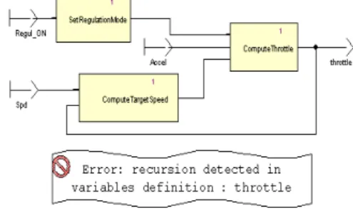
SCADE provides an approach to properly deal with issues of timing and causality. Causality means that if datum x depends on datum y, and then y has to be available before the computation of x starts. A recursive data circuit poses a causality problem, as shown in Figure 3, where “throttle” depends on itself, via the ComputeTargetSpeed and ComputeThottle node. The SCADE semantic checker detects this error and signals that throttle has a recursive definition.
Figure 3: Detection of a causality problem Inserting an FBY (delay) operator in the feedback loop solves the causality problem, since the input of the ComputeTargetSpeed block is now the value of throttle from the previous cycle as shown in Figure 4
Functional Dependency and Concurrency
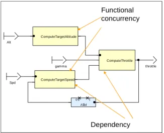
The SCADE language provides a simple and clean expression of concurrency and functional dependency at the functional level, as illustrated by Figure 4.
SetRegulationMode and ComputeTargetSpeed are functionally concurrent, since they are independent; the relative computation order of these blocks does not matter (since in SCADE there are no side effects). ComputeThrottle functionally depends on an output of ComputeTargetSpeed.
FB Y 1 0.0 throttle gamma Spd Alt ComputeThrottle ComputeTargetSpeed ComputeTargetAltitude Functional concurrency Dependency
Figure 4: Functional expression of concurrency The application is described in terms of logically concurrent activities in block diagrams or SSMs. The user needs not spend time performing tedious and error prone dependency analyses to determine the sequencing manually; the focus is elevated to the functions rather than the coding.
Concurrency and dependencies are taken into account during code generation. KCG, the current commercial code generator is able to automatically generate sequential deterministic code for a reasonably wide category of situations (see sections 3 and 4 for the scope and limitations of sequential implementation). This code strictly conforms to the model’s semantics. Notice that there is no overhead for communication which is implemented internally using well-controlled shared variables and avoiding any context switching.
Safe State Machines for discrete control
Discrete control is used when the behaviour varies qualitatively as a response to events. This is characteristic of modal human-machine interface, alarm handling, complex functioning mode handling, or communication protocols.
SCADE hierarchical state machines are called Safe State Machines (SSM). These can be freely mixed with data flow. SSMs are hierarchical. States can be either simple states or macro states, themselves recursively containing a full SSM. When a macro state is active, so are the SSMs it contains. When a macro state is exited by taking a transition out of its boundary, the macro state is exited and all the active SSMs it contains are pre-empted, whichever state they were in. State machines communicate by exchanging signals, which may be scoped to the macro state that contains them.
Activ e Stdby Condition Speed < SpeedMin Accel > PedalsMin Speed > SpeedMax <SM3> StandBy CruiseState STDBY On local_CruiseSpeed CruiseState ON ThrottleCmd Speed 2 CruiseRegulation 1 Stdby Condition 1
not Stdby Condition
Figure 5: State Machine Fragment for Cruise Control The definition of SSMs strictly forbids dubious constructs found in other hierarchical state machine formalisms: transitions crossing macro state boundaries, transitions that can be taken halfway and then back-tracked, and so on. These are non-modular, semantically ill defined, and very hard to understand, hence are inappropriate for safety-critical designs. They are usually not recommended by methodological guidelines.
3. Traditional Scheduling Schemes for Multi-Rate Synchronous Software
Separate Development and Tasking Technique With this technique, software modules that have to run at different rates are allocated to different tasks each running at the appropriate rate. These modules, which may be designed each as a synchronous model, are developed, scheduled and verified separately. There is no formal definition of the global behaviour. The global behaviour is generally not deterministic in the presence of execution time variations, and there are no techniques for accurately verifying this global behaviour, since testing or simulation can only explore parts of the complex state space.
Single Tasking Scheme
All software components run in a single task, activated at the highest frequency. This is best illustrated by the following example.
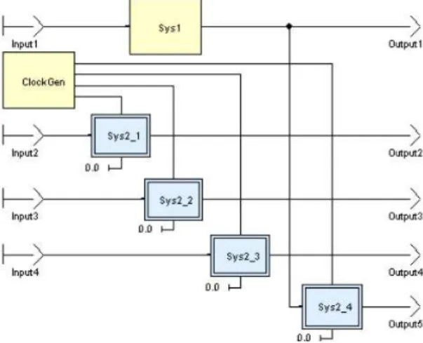
The following application has two rates: Sys1, which is as fast as the top-level, and Sys2, which is four times slower, as shown on Figure 6.
Sys2 is only executed every fourth time. It is executed within the same main top-level function as Sys1. This means that the code of whole application, Sys1 + Sys2, is executed at the fastest rate, which needs a powerful CPU.
Figure 7: Basic Bi-rate Scheduling
The solution consists in splitting the slow part into several smaller slow parts and distributing their execution on several fast rates. This is a safe way to design a multi-rate application. Scheduling of this application is fully deterministic and can be statically defined. The previous application example can be redesigned as shown on Figure 8.
Figure 8: Multi-cycle Bi-Rate Model
The slow part, Sys2, is split into four subsystems. Note that any data exchanges are possible between these decomposed parts, provided causality is respected (it is verified by the qualified code generator) and will be reflected correctly in the single task implementation.
These subsystems are executed sequentially, one after the other, in four cycles, as shown on Figure 9.
Figure 9: Multi-cycle Bi-rate Scheduling
Advantages of this architecture:
• It uses static scheduling; it is fully deterministic, and there is no risk of deadlock.
• Data exchanges between subsystems are fully handled by SCADE (both at model level and by auto-code generator), respecting functional dependencies.
• Synchronous simulation and proof are valid for the generated code.
Constraints of this architecture:
• It requires breaking the slow part into execution slices that are small enough to fit into the available time slots. This may be problematic when the control structure of the slow part does not match such a slicing.
• It is necessary to handle the WCET (Worst Case Execution Time) of each slice to validate scheduling in all cases. The sum of the WCET of low part slices may be much larger than the WCET of the complete slow part.
• Each change in the contents of the slow part may require redoing complex breakdown and WCET analysis.
4. The Synchronous Multi-Rate Multi-Task Scheduling Scheme
Objective of the presented technique
The presented technique has the following objectives:
• Support the global design and implementation of multi-rate software in situations where slicing of the slow part is problematic as explained above.
• Support analysis of the global behaviour at the model level, for instance by simulation or formal verification.
• To be implementable on a simple static priority-based pre-emptive scheduler.
• Ensure functional equivalence between the functional model and its implementation running in physical time. This equivalence has to be based on solid theoretical foundations.
• Be efficient in terms of computing resources.
• Last but not least, for usability in an industrial context, this shall be achieved by adhering to a standardised architecture with simple and easy to verify design rules.
Foundations
Contrary to a common prejudice, the scope of synchronous techniques is not inherently limited to periodic software, where single thread code is generated from a model. It is also a powerful framework for describing and analysing a wider class
of real time systems, such as multi-periodic or even sporadic processing.
The technique presented in this paper is based on solid theoretical foundations, published in [3]. Compared to [3], we rely on usage conditions which simplify the design and verification tasks, thus making the approach affordable to common engineering practice. Tasks are periodic (not sporadic) and the presentation is limited to a situation with 2 tasks. We found these conditions appropriate for our application context. More general hypotheses may be adopted at the price of a higher complexity, using the approach described in [3].
Scheduling
The application is composed of two periodic parts, named “minor” (noted “m”) for the faster one and “major” (noted “M”) for the slower one. TM (the period for M) is an integer multiple of Tm (the period for m).
Deadline monotonic pre-emptive scheduling is used. Each task is assigned a unique priority. The task with the highest priority executes first. Tasks are periodic, and all periods are multiples of the shortest period called the ‘base period‘.
The following constraints on the Worst Case Execution Time (WCET) are imposed:
1. WCET(minor) + other < Tm
2. N*WCET(minor+other)+WCET(Major)< TM where other includes time needed by other tasks (ex; input/output) and context switching.
What is the Central Issue?
No model or implementation can be considered as good by itself: we need representativeness of the model with respect to the implementation and determinism of both the implementation and the model. The central issue is to define a consistent set of modelling and implementation rules such that the behaviour of the model (as defined by the synchronous semantics, and reflected by simulators or formal verification tools) and the behaviour on the target are functionally equivalent: the same input sequence produces the same output sequence at the times where a subsystem communicates with outside. Indeed, the model semantics are defined in terms of logical instants (cycles), with no physical duration, while the execution of the real implementation runs in physical time. Execution time may vary within the limits defined in the previous section.
For a single task implementation, equivalence is simply ensured if the Worst Case Execution Time (WCET) is smaller than the CPU time allocated to the task for a period. For a multi-rate, multi-task execution scheme, this is more complex; we also need to ensure that actual data, computation and ordering remain consistent despite variations in
execution time under the WCET and scheduling hypotheses described above.
As we shall see in the next sections, the key of this problem lies in the communication: what should be communicated and when should communication occur?
Global Application Model
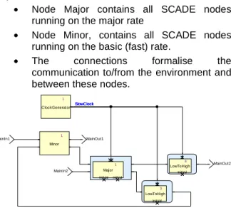
We model the scheduling and communication in SCADE by creating a root node containing an instance of the following children nodes (see Figure
10):
• Node Major contains all SCADE nodes running on the major rate
• Node Minor, contains all SCADE nodes running on the basic (fast) rate.
• The connections formalise the communication to/from the environment and between these nodes.
1 ClockGenerator 3 LowToHigh InitVal 4 LowToHigh InitVal MainOut2 MainOut1 MainIn2 MainIn1 1 Major InitVal InitVal 1 Minor SlowClock SlowClock SlowClock
Figure 10: Model of a Synchronous Bi-Rate System The scheduling is expressed by putting the major node under control of a clock named SlowClock, which is true every major cycle. From a synchronous viewpoint, even the computation of the major node is instantaneous. In the real world, the minor process may interrupt the major process before it has completed its computation, and one may think that the synchronous model is inherently inappropriate to match reality. We will see in the following sections that this depends on communication. For the time being, let us consider that we have no formal model of communication between the major and minor nodes. We will define this communication based on analysis of the relationship between the model and the real world.
Minor to Major Communication
Communication from minor to major cycle can occur instantly after completion of minor cycle computation and is modelled by a direct connection from minor to major nodes. However, minor shall not communicate to Major during a computation of Major (see Figure 11). The reason is that this might lead M into an inconsistent state. Assume for instance that m passes related data such as a pressure and its
related validity flag and that the output of m in cycle k contains a valid pressure with the validity flag set to true. Assume that M starts computing, sees that the pressure is valid and bases following computations of its current cycle on this validity. If m(k+1) m puts an invalid pressure (even with the validity flag set to false) into M’s input vector, this may clearly lead M to perform erroneous computations. The general rule for synchronous software is that the input vector of a component shall remain frozen during the complete computation of its cycle; this also concerns data coming from other parts of the real world.
Major to Minor Communication
Communication from major node to minor node requires specific handling. For simplicity, we will use as an example a situation where TM=2*Tm.
First of all, let us analyse the most usual case, where M takes nearly as much as it WCET, i.e. it completes just before the next minor cycle where it will perform its new major cycle, as shown on Figure 11. In cycle k m is executed first and then it passes its output to M, which starts computing. M is interrupted and suspended by m executing its k+1 cycle. Then M resumes and completes computation of its major cycle during cycle k+1. The output of M is used as input by m at cycle k+2. m Finish M m m k+1 k+2 Begin M Suspend M
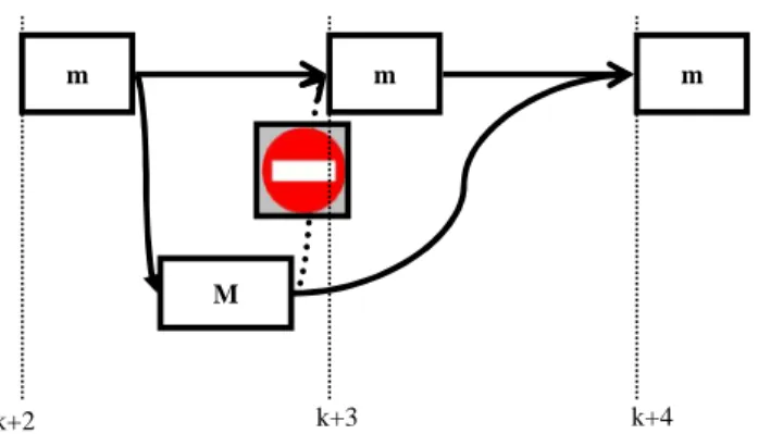
Figure 11: Case when M computes slowly Now, let us analyse the less intuitive situation shown in Figure 12, were (in some cycles) M needs significantly less than its WCET. In the example, M completes during cycle k+2, rather than cycle k+3. It would seem natural that M sends its output to computation k+3 of m. But if we do that, then the global behaviour will vary, depending on the current execution time of M. Even a variation of a microsecond in execution time of M may abruptly switch from the previous situation to this situation or vice-versa (this is a kind of chaotic behaviour). The global behaviour becomes non deterministic and impossible or extremely difficult to analyse.
m
M
m m
k+2 k+3 k+4
Figure 12: Case where M computes faster than usual
So, in order to keep the system deterministic, we should systematically communicate from M to m at the beginning of the minor cycle where M will starts its next major cycle, even if M finishes earlier.
Model of the Communication
We have analysed the behaviour in real time, so we can now define the communication scheme that will represent this consistently in the global model. The "LowToHigh" node is used in order to ensure that communication from major to minor occurs with a delay of one major cycle. Its reference definition (Figure 13) is a “fby” operator (unit delay) under activation condition by the slow clock
.
3 LowToHigh InitVal InitVal FBY 1 Output1 Input1
Figure 13: Low To High Node
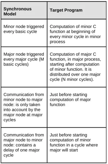
Summarizing Mapping between Logical and Real Time
Table 2 summarises the mapping between the
SCADE design specification (which is defined in logical synchronous time) and the implementation (which runs in real time on 2 processes and where computation time is variable).
Table 2: Mapping Logical to Physical Time
Synchronous
Model Target Program
Minor node triggered every basic cycle
Computation of minor C function at beginning of every minor cycle in minor process
Major node triggered every major cycle (M basic cycles)
Computation of major C function, in major process, starting after computation of minor function. It is distributed over one major cycle (N minor cycles).
Communication from minor node to major node: is only taken into account by the major node at major cycles
Just before starting computation of major function
Communication from major node to minor node: contains a delay of one major cycle
Just before starting computation of minor function in a cycle where major will start
Implementation of the Model
The code for nodes minor and Major can easily be automatically generated as pure sequential code, using a code generator such as the SCADE qualified code generator KCG. For each node there are two C functions: an initialisation function and a cyclic function, to be called at each cycle where the corresponding node has to be executed.
On the contrary, the root node, modelling activation of minor and major nodes, and communication between them has to be understood as a conceptual model. It cannot be implemented by simple sequential code. This is for instance beyond the scope of the current KCG. However this is not a major issue, since the code implementing the root node is quite simple. It just contains:
• Scheduling of minor an major processes using rate monotonic scheduling
• Transfer of data between the processes in the exact conditions described above
Data transfer has to be triggered either by the scheduler or by the fast process, if it can communicate with the slow process via shared memory.
It has to be implemented partially manually, possibly using KCG as a support to generate part of that code (in particular data type definitions and communication patterns).
Extension to Multi-Rate Software
Some reasonably simple extensions of the above analyses can be made for periodic multi-rate software when rates ratios are all a power of two (more general situations require the solution described in [3]).
First of all the principle for communication from a slow node to a fast node remains the same:
• In the model, communication from a slow node to any other node has to be modelled as a delay of the clock of the slow node
• In the implementation, communication from the slow task to any other task has to occur at the beginning of the next slow cycle
Second, the introduction of modules with intermediary rates introduces additional potential problems: the start of the slowest computation may be delayed by a task with an intermediary priority up to another cycle. m complete M1 m m M1 m m k k+1 k+2 k+3 k+4 Begin M1 Suspend M1 Begin M2 Suspend M2 resume M2 complete M2 Suspend M2
Figure 14: Three rate scheduling and communication So, the rule is the following; when a task A produces data that is consumed by a lower rate task B, it has to write into an (A,B) communication buffer the data corresponding precisely to the basic cycle where the slower task is supposed to start logically (and not when it really starts). In the example shown on
Figure 14, if medium priority task M1 completes only
in cycle k+1, it will delay the start of the lowest priority task M2. Yet, m should communicate to M2 its output from cycle k, and not its output from cycle k+1.
5. Application to Avionics Equipment Software
Context
Intertechnique company is part of Zodiac Aircraft Systems Segment. Its fuel management, oxygen and life support, electrical power management and monitoring and management safety-critical systems are installed in the airplanes and helicopters of all the leading international airframe manufacturers. Intertechnique chose to develop the software of a piece of safety-critical avionics equipment using the SCADE tool.
The software is bi-rate deterministic scheduled. Two models were created, one for each task (minor_process, major_process).
To check the behaviour of the global software, simulations were performed to make minor_process and major_process work together.
Multi-task issues
The main effort was the management of data exchanges between both tasks, as explained in the previous section. The decision was taken to experiment the use of KCG to generate a code which could work correctly on the real target. Since KCG is designed for generating single thread code, the code generated by KCG from the root node modelled in Figure 10 would not work correctly on the real target. The following approach has been adopted: build a root node such that:
• From a modelling perspective it should be semantically equivalent to the model of Figure
10
• The generated code is such that it communicates appropriately thanks to buffering and triggering conditions.
Communication from minor_process to major_process can occur instantly after completion of minor_process; however, re-entrance may have unwanted side effects on major_process.
Since KCG passes structured data by reference, it might happen that a minor_process pollutes the inputs of the running major_process which it interrupts.
On the other hand, inconsistencies can occur between inputs of minor_process of the first minor cycle and minor_process of the second minor cycle if communication from major_process to minor_process occurs instantly after completion of major_process.
Thus, in order to ensure determinism, the communication from major to minor cycles shall occur only after full completion of a major cycle, rather than as soon as computation is completed
Adopted Solution
In order to avoid these communication issues, dedicated nodes were designed.
Communication from minor_process to major_process Inputs of major node shall stay invariant during major node processing. Since the actual implementation runs on two threads (minor and major), communication from major node to minor node requires specific handling.
This is ensured by inserting a dedicated node MinorToMajor activated before executing the node major_process. This MinorToMajor node shall not be interrupted.
Input1 Output1
Figure 15: MinorToMajor node definition The SCADE activation operator (condact) ensures that when activation condition is true, Output1 takes Inputs1 value and when activation condition is false, Output1 stays invariant.
Communication from major_process to minor_process Inputs of the minor_process shall not be dependent of major_process time processing.
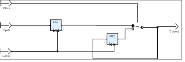
Inserting a dedicated node MajorToMinor ensures that communication from major_process to minor_process occurs only before the first minor_process of the first minor cycle. This node is activated at each cycle (no activation condition).
FBY 1 FBY 1 Output1 InitVal Input1 C lock
Figure 16: MajorToMinor node definition: Leftmost "fby" stores the output of major_process; rightmost "fby" sends the last valid output from major_process. The switch sends the updated major_process output stored by the leftmost “fby” and updates the rightmost “fby”.
The simulation scheduler node definition is then as follows, and includes also “and” gates to model a scheduling validity signal:
LL_Transf erMinorToMajor
RootMajorWeight RootMajorW eightOut RootMinorW eightOut
RootMinorW eight LL_N oSc heduleError
LL_D oMinorCy c le LL_DoMajorCy c le LL_Trans f erMajorToMinor
1 in_MinorToMajor I nitMinW eightO2_Cst InitMinW eightO 1_Cs t InitMajorWeight_Cs t 1 in_MajorToMinor 1 MinorProc es s 1 MajorProc es s Figure 17: Simulation Root Node
Benefits and Limitations
Model driven simulation enables testing of functional software very early in the development cycle. Scheduling the model using the chosen architecture allows a global simulation and the detection of potential errors in data exchanges between minor and major cycles.
This simulation activities reduced integration time on hardware by around 60%, most of functional malfunctions being detected early on simulation environment.
Since the code generator is not designed to create multi-task code, human review of the code generated for the root node is required in order to check that it is compatible with the multi-task real-time integration. The code for minor and major nodes runs in the nominal conditions for which KCG has been designed and qualified and so does not need to be reviewed.
Perspectives
Intertechnique chose to develop more software using the SCADE tool. SCADE 6, implementing new constructs, allows the use of model driven development on more programs than the previous versions.
These new constructs, especially qualified state machines could ease the development of real-time simulations. This will be carefully studied by Intertechnique to continue reducing integration costs using scheduling simulation on simulation environment.
6. Conclusion
We have defined a simple and efficient technique for the development and verification of multi-rate software. This technique makes it possible to specify, implement and accurately verify the global behaviour of a multi-rate application, without paying the price for a complex synchronisation mechanism, such as semaphores or polling, and introduces no risk of deadlock. This was made possible by using the synchronous software concepts, not just as a means for implementing a piece of software in a program loop, but also as a powerful conceptual framework able to describe behaviour distributed over several tasks.
Future work will explore the following areas: 1 Use of the extended approach described in [5] 2 Automation of the implementation of
scheduling and communication
7. Acknowledgement
The authors acknowledge the contribution of Paul Caspi (Verimag), Thierry Lesergent (Esterel Technologies) and Sébastien Penot (Intertechnique/Turbomeca) to this work. The
foundations of this technique are based on results of the EC project RISE (38117) and dissemination is partly supported by the EC project INTEREST (3361).
8. References
[1] N. Halbwachs, P. Caspi, P. Raymond, and D. Pilaud. “The synchronous dataflow programming
language Lustre”. Proceedings of the IEEE,
79(9):1305-1320, September 1991.
[2] “SCADE Language Reference Manual”, Esterel Technologies 2007
[3] N. Scaife and P. Caspi: “Integrating model-based
design and preemptive scheduling in mixed time
and event-triggered systems” Euromicro
conference on Real-Time Systems (ECRTS'04), Catania, Italy, June 2004
[4] N. C. Audsley, A. Burns, M. F. Richardson, and A. J. Wellings. “Hard Real-Time Scheduling: The
Deadline Monotonic Approach. In Proceedings 8th IEEE Workshop on Real-Time” Operating Systems
and Software, Atlanta, 1991. 3.3
[5] S. Tripakis, C. Sofronis, N. Scaife and P. Caspi. “SemanticsPreserving and MemoryEfficient Implementation of InterTask Communication on StaticPriority or EDF Schedulers” - EMSOFT 05
[6] Pilarski, F “Cost effectiveness of formal methods in
the development of avionics systems at
Aerospatiale”, Digital Avionics Systems
Conference, 1998. Proceedings., 17th DASC [7] G. Legoff & P. Sainton, “Using synchronous
language for signalling”, Computers in Railways V,
Vol 1, 1996
[8] J.-M. Palaric and A. Boué. “Advanced safety I&C
system for nuclear power plants”. In ENC'98 World
Nuclear Congress, Nice, France, October 1997 [9] A Benveniste, P Caspi, Stephen A. Edwards, N.
Halbwachs, P. Le Guernic, R. De Simone “The
Synchronous Languages 12 Years Later”,
PROCEEDINGS OF THE IEEE, VOL. 91, NO. 1, JANUARY 2003
[10] F. Boussinot, R. de Simone, “The Esterel
language”, Proc. IEEE, vol. 79, pp. 1293–1304,
Sept. 1991.
[11] P. Le Guernic, T. Gautier, M. Le Borgne, and C. Le Maire, “Programming real-time applications with
SIGNAL”, Proc. IEEE, vol. 79, pp. 1321–1336,
Sept. 1991
9. Glossary
KCG: SCADE qualified code generator
SCADE: Safety Critical Application Development
Environment