HAL Id: hal-00838139
https://hal.archives-ouvertes.fr/hal-00838139
Submitted on 26 Jun 2013
HAL is a multi-disciplinary open access
archive for the deposit and dissemination of
sci-entific research documents, whether they are
pub-lished or not. The documents may come from
teaching and research institutions in France or
abroad, or from public or private research centers.
L’archive ouverte pluridisciplinaire HAL, est
destinée au dépôt et à la diffusion de documents
scientifiques de niveau recherche, publiés ou non,
émanant des établissements d’enseignement et de
recherche français ou étrangers, des laboratoires
publics ou privés.
PICARD payload thermal control system and general
impact of the space environment on astronomical
observations
Mustapha Meftah, Abdanour Irbah, Alain Hauchecorne, Jean-François
Hochedez
To cite this version:
Mustapha Meftah, Abdanour Irbah, Alain Hauchecorne, Jean-François Hochedez. PICARD payload
thermal control system and general impact of the space environment on astronomical observations.
Proceedings SPIE 8739, Sensors and Systems for Space Applications VI, Apr 2013, Baltimore, United
States. pp.87390B, �10.1117/12.2010178�. �hal-00838139�
PICARD payload thermal control system and general impact
of the space environment on astronomical observations
M. Meftah
a,*, A. Irbah
a, A. Hauchecorne
a, and J.-F. Hochedez
aa
LATMOS - Laboratoire Atmosph`
eres, Milieux, Observations Spatiales, CNRS – Universit´
e
Paris VI & Universit´
e de Versailles Saint-Quentin-en-Yvelines – IPSL, F-78280, Guyancourt, Fr
ABSTRACT
PICARD is a spacecraft dedicated to the simultaneous measurement of the absolute total and spectral solar irradiance, the diameter, the solar shape, and to probing the Sun’s interior by the helioseismology method. The mission has two scientific objectives, which are the study of the origin of the solar variability, and the study of the relations between the Sun and the Earth’s climate. The spacecraft was successfully launched, on June 15, 2010 on a DNEPR-1 launcher. PICARD spacecraft uses the MYRIADE family platform, developed by CNES to use as much as possible common equipment units. This platform was designed for a total mass of about 130 kg at launch. This paper focuses on the design and testing of the TCS (Thermal Control System) and in-orbit performance of the payload, which mainly consists in two absolute radiometers measuring the total solar irradiance, a photometer measuring the spectral solar irradiance, a bolometer, and an imaging telescope to determine the solar diameter and asphericity. Thermal control of the payload is fundamental. The telescope of the PICARD mission is the most critical instrument. To provide a stable measurement of the solar diameter over three years duration of mission, telescope mechanical stability has to be excellent intrinsically, and thermally controlled. Current and future space telescope missions require ever-more dimensionally stable structures. The main scientific performance related difficulty was to ensure the thermal stability of the instruments. Space is a harsh environment for optics with many physical interactions leading to potentially severe degradation of optical performance. Thermal control surfaces, and payload optics are exposed to space environmental effects including contamination, atomic oxygen, ultraviolet radiation, and vacuum temperature cycling. Environmental effects on the performance of the payload will be discussed. Telescopes are placed on spacecraft to avoid the effects of the Earth atmosphere on astronomical observations (turbulence, extinction, ...). Atmospheric effects, however, may subsist when spacecraft are launched into low orbits, with mean altitudes of the order of 735 km.
Keywords: PICARD, SODISM, Telescope, Sun, Thermal Control System, Contamination, Space environment
1. INTRODUCTION
PICARD, a French solar physics spacecraft (Figure 1) was launched from the Dombarovsky air base near Yasny (Russia). The mission was named in honour of the Seventeenth century French astronomer Jean Picard (1620-1682), who made the first long-term measurements of the solar diameter. Picard is an investigation dedicated to the simultaneous measurement of the absolute total and part of spectral solar irradiance, the measurement of solar diameter by metrological instrumentation, and the study of the Sun’s interior through helioseismology.
The scientific objectives of the mission are described in detail by Thuillier et al.1 in 2006. PICARD with French
multi-institutional and international cooperation operates during the solar cycle 24. A dawn/dusk orbit with LTAN (Local Time of Ascending Node) at 6:00/18:00 hours is being used with an altitude of 735 km (period of 99.4 minutes) and an inclination of 98.29 degrees. The selection of a SSO orbit (Sun Synchronous Orbit) permits the period of eclipses to be limited to around 90 days (during winter solstice), and the duration of eclipses to a maximum of 20 minutes.
The Picard spacecraft (total mass near 130 kg) consists of a box structure (0.9 m x 0.8 m x 1.1 m) with a single solar panel. The platform structure is made of a massive aluminium base plate interfacing with the launcher, four lateral honeycomb panels, and a payload base plate (Figure 2). The payload is composed of three instruments
* Corresponding author
and an electronic box named PGCU (PICARD Gestion Charge Utile or Payload Management Unit) including the electronics associated with SODISM (SOlar Diameter Imager and Surface Mapper) and the processor in charge of the payload data handling and control. The scientific measurements are achieved by:
- PREMOS2(PREcision MOnitoring Sensor) is made of four units: a set of three Sun-photometers and a PMO6
radiometer as used on SoHO to measure the absolute Total Solar Irradiance. The Sun-photometers are used to study the ozone photochemistry, to perform helioseismologic observations, and to relate radiance/irradiance observations with the corresponding images recorded by the SODISM imaging telescope as described below. PREMOS measures at 215, 268, 535, 607, and 782 nm. The PREMOS instrument is under the responsibility of the Physikalisch-Meteorologisches Observatorium Davos - World Radiation Center (PMOD - WRC, Switzerland).
- SOVAP3 (SOlar VAriability PICARD) instrument provided by the Royal Meteorological Institute of Belgium
(RMIB) measures the absolute Total Solar Irradiance. This instrument is a radiometer of DIARAD type used in previous space missions, SOHO, and SOLCON on the Space Shuttle (1992, 1993, 1994, 1998, and 2003). There is also a bolometer provided by the Royal Observatory of Belgium (ROB).
- SODISM4is an imaging telescope measuring the solar diameter and limb shape, and performs helioseismologic
observations to probe the solar interior. The solar diameter is measured at three wavelengths (535.7, 607.1 and 782.2 nm) in the photospheric continuum. Images in the Ca II line (393.37 nm) are used to detect active regions near the solar limb that may alter the diameter measurements. These images are also used to measure the solar differential rotation as well as for Space Weather, together with images in the 215.0 nm wavelength. This instrument is provided by CNRS (Centre National de la Recherche Scientifique).
Figure 1. Artist’s view of the spacecraft. Figure 2. Spacecraft and instruments allocation.
- The purpose of PICARD payload thermal control
Throughout the mission, thermal control ensures that each instrument or equipment unit is maintained at tem-peratures consistent with nominal operation. Most of instruments only operate correctly if maintained at the right temperature and if temperature changes are within acceptable limits. In our terrestrial environment or in laboratories, temperatures are often regulated. Spacecraft environments in orbit are completely different (vacuum, microgravity, radiation, ...). Thermal control surfaces and payload optics are exposed to space envi-ronmental effects including contamination, atomic oxygen, ultraviolet radiation and vacuum temperature cycling. This means that thermal conditions are very particular and likely to cause important changes in temperature. Correct temperature can only be achieved by specific thermal control technology. Thermal control of the payload is fundamental. To provide a stable measurement of the solar diameter to a few milli-arcseconds over three years duration of mission, the SODISM telescope mechanical stability has to be intrinsically excellent and thermally controlled. It is necessary to ensure low temperature gradients (spatial δT /δx), and low temperature variations (temporal δT /δt) for a metrological instrument.
- Contamination and environmental effects on the performance of the payload
Materials having low values of solar absorptance αs are often used for reflective surfaces designed to minimise
heat absorption. Thermal balance can be maintained over the payload lifetime only if the reflective surfaces maintain their thermal properties. The presence of contamination on thermal control surfaces alters absorp-tance/emittance ratios and changes thermal balance leading to increased payload temperatures. Contamination in optical instruments decreases signal throughput, thus further decreasing performance. The PICARD payload is sensitive to contamination. It was necessary to quantify the critical level of contamination and to enforce contamination control to ensure compliance with requirements. This work is rather complex and not trivial. During fabrication, assembly, integration, test, launch and operation in order to maintain those levels on orbit (opening the door of the instrument one month after the outgassing phase during the commissioning phase), procedures and processes were necessary. Selected payload materials (near optical elements) comply with the following conditions: TML <0.1% (Total Mass Loss) and CVCM <0.01% (Collected Volatile Condensable Mate-rial), according to ESA-PSS-51 (guidelines for spacecraft cleanliness control from European Space Agency), but are not always sufficient for very sensitive surfaces. Effective contamination control is essential for the success of PICARD mission, because the presence of contamination degrades the performance of payload hardware. The payload thermal coatings suffer outgassing and mass loss due to their direct exposure to the thermal en-vironment and high vacuum in space. They also suffer from the ultraviolet radiation and vacuum temperature cycling. Flight performance of the payload thermal control is affected by the contamination. Effects of space environments on the performance of the payload appear and are greater than expected.
In the next section, we describe the PICARD payload TCS (Thermal Control System). In subsequent sections, we present PICARD payload thermal test, in-orbit thermal performance, PICARD/SODISM observational results, and effects of space environments on PICARD/SODISM measurements.
2. THE PICARD PAYLOAD TCS DESIGN
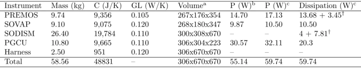
Table 1 summarises the main characteristics of the PICARD payload. PGCU is an onboard electronics unit which includes all functions necessary to operate the three instruments (formatting of telemetry, reception of commands, image compression, thermal control and power supply for SODISM, and safety management). PREMOS has its own thermal control. The power consumption of the payload (in orbit, see Table 1) is lower than expected (prediction before the launch).
Table 1. PICARD payload main characteristics.
Instrument Mass (kg) C (J/K) GL (W/K) Volumea P (W)b P (W)c Dissipation (W)c
PREMOS 9.74 9,356 0.105 267x176x354 14.70 17.13 13.68 + 3.45† SOVAP 9.10 9,075 0.120 268x180x347 9.87 10.50 10.50 SODISM 26.40 19,784 0.110 300x308x670 – – 4 + 7.81† PGCU 10.80 9,665 0.110 306x304x223 30.57 32.11 20.3 Harness 2.50 951 0.120 306x670x670 – – – Total 58.56 48831 – 306x670x670 55.14 59.74 59.74
a Dimensions in mm,bIn orbit, c Prediction (before the launch),† Active thermal control of instrument
2.1 Temperature requirements
The purpose of the thermal control design is to maintain all the instruments or equipment units of the spacecraft system within their temperature limits for all mission phases from launch to end of life. The thermal control (passive and active) ensures that the payload, and its subsystems work within the acceptance temperature range (see Table 2) in every phase of the mission.
The qualification margin is equal to |TQ-TA|. The uncertainties (coming from complex view factors, surface
properties, radiation environment, joints, interface conduction, and ground tests) recognise that many
assump-tions are used in the development of thermal mathematical models (uncertainties of 5oC after thermal balance
Table 2. PICARD payload temperature requirements.
Payload Requirements TQ TA
PREMOS* Minimum Non-Operating Temperature -40oC –
Minimum Operating Temperature -20oC –
Maximum Operating Temperature 60oC –
Maximum Non-Operating Temperature 65oC –
SOVAP Minimum Non-Operating Temperature -40oC -30oC
Minimum Operating Temperature -25oC -20oC
Maximum Operating Temperature 45oC 40oC
Maximum Non-Operating Temperature 60oC 50oC
SODISM Minimum Non-Operating Temperature -35oC -30oC
Minimum Operating Temperature 0oC 5oC
Maximum Operating Temperature 40oC 35oC
Maximum Non-Operating Temperature 50oC 45oC
PGCU Minimum Non-Operating Temperature -40oC -35oC
Minimum Operating Temperature -30oC -20oC
Maximum Operating Temperature 50oC 40oC
Maximum Non-Operating Temperature 60oC 55oC
*Proto-flight model, T
Q: Qualification levels, TA: Flight acceptance levels
2.2 The PICARD payload TCS
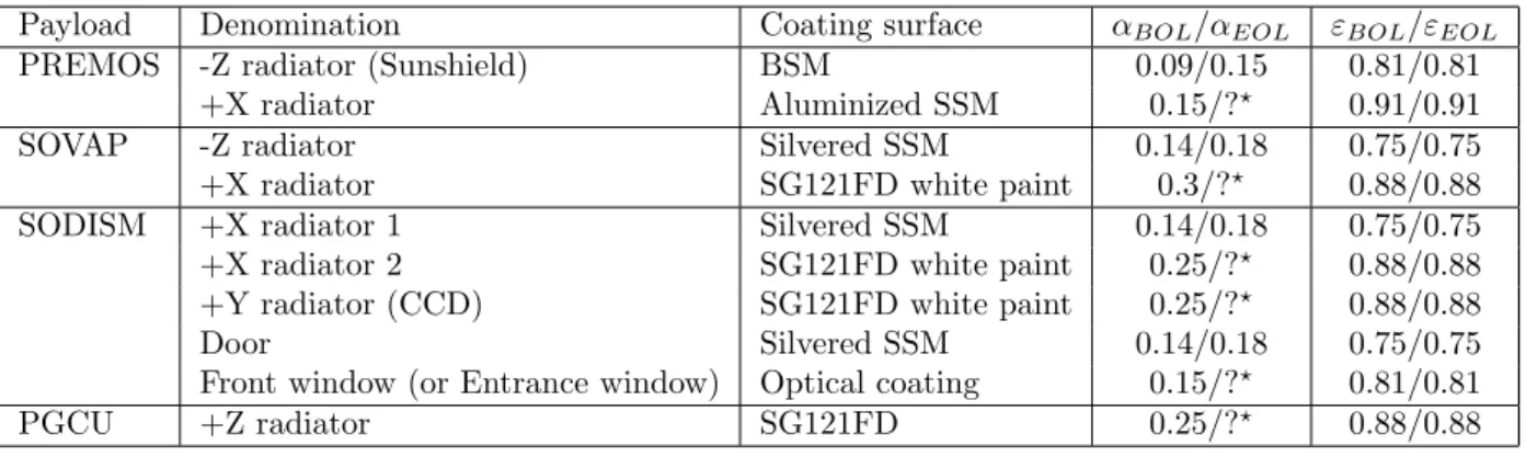
On the payload, there is passive thermal control: thermal insulation (MultiLayer Insulation or MLI), radiators, surface finishes (coatings, paints, treatments, Second Surface Mirrors, tape, Optical Solar Reflector), and thermal washers to reduce the thermal coupling at platform interfaces. There is also active thermal control: resistance heaters with mechanical thermostat, and electronic controllers. The PREMOS instrument is thermally regulated (locally) in operating mode. SOVAP and PGCU are not thermally regulated. SODISM is thermally regulated (overall) in operating mode with the exception of elements in the front face (optical front window, door). The PICARD payload consists of several radiators: devices with a large surface area used to radiate heat (heat rejection). For our application, it is desirable to have a high value of emissivity ε (3 to 100 µm wavelength band) and a low value of α (0.2 to 3 µm wavelength band) in order to maximise the heat rejection in space and to minimise the solar radiation. Thermal coatings are very efficient. Unfortunately, they will degrade over time. The position of the radiators is shown in Figure 3. The spacecraft, during integration, is shown in Figure 4. Thermal control coatings surfaces, such as white paints, silvered or aluminized Second Surface Mirrors (SSM), Back Surface Mirrors (BSM), that have special radiation properties are used (Table 3).
Table 3. PICARD payload radiators and optics characteristics.
Payload Denomination Coating surface αBOL/αEOL εBOL/εEOL
PREMOS -Z radiator (Sunshield) BSM 0.09/0.15 0.81/0.81
+X radiator Aluminized SSM 0.15/?? 0.91/0.91
SOVAP -Z radiator Silvered SSM 0.14/0.18 0.75/0.75
+X radiator SG121FD white paint 0.3/?? 0.88/0.88
SODISM +X radiator 1 Silvered SSM 0.14/0.18 0.75/0.75
+X radiator 2 SG121FD white paint 0.25/?? 0.88/0.88
+Y radiator (CCD) SG121FD white paint 0.25/?? 0.88/0.88
Door Silvered SSM 0.14/0.18 0.75/0.75
Front window (or Entrance window) Optical coating 0.15/?? 0.81/0.81
PGCU +Z radiator SG121FD 0.25/?? 0.88/0.88
Figure 3. Radiators of the spacecraft. Figure 4. Spacecraft during integration.
2.3 SODISM thermal design
SODISM is the most critical instrument. The resulting temperature range in orbit is foreseen to be about -35oC
to 50oC in non-operating mode (Table 2), avoiding any degradation of structure, electronics and optical parts.
SODISM requires a very high level of thermo-mechanical stability to obtain the desired accuracy on solar diameter measurements (in operating mode). A complex thermal control is implemented on the telescope and consists of i) efficient thermal protection (Multi Layer Insulation or MLI) of the overall telescope, ii) protection from solar illumination, iii) the implementation of a complex heating system monitored by thermal sensors. The thermal control includes the necessary hardware to control the temperature of all components of the telescope, including the structure, the mirrors, the mechanisms and also the temperature regulation algorithm. The SODISM thermal control is based on a Proportional Integral (PI) regulation. The instrument stability strongly depends upon precise regulation of all defined parameters. The temperature control provides several independent temperature controlled areas located over the structure. Each area consists of a set of heaters, mounted in the same electrical circuit, over which the heating power is adjusted based on the temperature measured through a temperature sensor located in the vicinity of the heaters. Most important temperature controlled areas are redundant. The temperature set point of each area is reprogrammable and was adjusted during the commissioning phase. 20
heating lines are used to thermally stabilise the instrument at ∼ 20oC (operating mode). Temperature sensors
are used for the temperature regulation process, as well as for temperature housekeeping over the telescope (45 sensors). The most sensitive elements are:
- The mirrors: they must be regulated (primary mirror at 25oC ±1oC and secondary mirror at 30oC ±1oC).
- The interference filters: they must be regulated at 20oC ±5oC (central wavelength stabilisation).
- The CCD (Charge Coupled Device): it has to be thermally regulated at -10oC ±0.2oC to have no area
deformations and low noise in images. The dark signal is an unwanted component of the recorded datum at each CCD picture element (pixel). The Telescope needs to be kept at room temperature, but the CCDs need to
be kept at extremely cold temperatures (∼ -40oC). This is extremely difficult to achieve, given that we are on a
low Earth orbit (LEO). In fact, the incident flux (Outgoing Longwave Radiation and Reflected Solar Radiation) at the CCD radiator are not negligible. In addition, the spacecraft has a small mass (thermal inertia) and the electrical power allocated to the thermal control of the instrument is low.
The front window is not temperature-regulated (passive thermal control). This is another problem related to the nature of the optical element (very low thermal conductivity and inability to integrate a thermal heater).
However, it is necessary to ensure its temperature (between 0 and 40oC during operating mode). The front
window is thermally insulated from the mechanical structure to avoid optical lens effects due to its deformations by thermal constraints.
2.4 The MLI (Multi Layer Insulation)
Each instrument or equipment unit of the payload has its own MLI. There is also MLI for the entire payload (to avoid solar trapping). Each instrument external blanket or MLI consists of 15 layers defined as follows: one external layer (space side, 25 µm Kapton), 13 intermediate layers (6 µm Mylar and Dacron) and 1 internal layer
(internal side, 25 µm Kapton). For the MLI, it is desirable to have a low value of εequivalent (0.014) and a
low value of λequivalent (0.025 W.m-2.K-1). The main characteristics of the payload external layer are: ε=0.77,
αBOL=0.32, and αEOL=0.49.
2.5 Thermal Environments
PICARD is a metrology mission. The flux variations (thermal environments) affect the temperature of the pay-load. When temperatures change (orbital variation, effect of eclipses, long-term variation), instrument performance is impacted. The annual mean global energy balance for the Earth-atmosphere system is very
important to understand. Of the 342 W/m2 incoming solar radiation (Shortwave Radiation), 67 W/m2 are
ab-sorbed during passage through the atmosphere (clouds). A total of 107 W/m2(Reflected Short-wave Radiation)
is reflected back to space (clouds and Earth’s surface) in the 0.2 to 3 µm wavelength band. Shortwave radiation is a term used to describe radiant energy with wavelengths near-UltraViolet (UV), in the VISible (VIS), and
Near-InfraRed (NIR) spectra. The remaining 168 W/m2 are absorbed at the Earth’s surface.
Figure 5. Earth Radiation Budget.
In order to maintain a stable climate, the Earth must be in energetic equilibrium between the radiation it receives from the Sun and the radiation it emits out to space. Outgoing Long-wave Radiation (OLR radiation in the 3 to 100 µm wavelength band) is the energy leaving the Earth as infrared radiation at low energy (235
W/m2 emitted). The OLR is affected by the Earth’s skin temperature, skin surface emissivity, atmospheric
temperature, water vapour profile, clouds and dust in the atmosphere, which tend to reduce it below clear sky values. Greenhouse gases, such as methane (CH4), nitrous oxide (N2O), water vapour (H2O) and carbon dioxide (CO2), absorb certain wavelengths of OLR adding heat to the atmosphere, which in turn causes the atmosphere to emit more radiation. The effect of clouds on the radiation budgets at the Top Of Atmosphere (TOA) derived
from the Earth Radiation Budget Experiment (ERBE) [Barkstrom et al.5] has been widely used to validate climate models and to improve cloud parameterisation schemes. The following Table 4 summarises the range of Direct Solar, Reflected Solar (Albedo), and Planetary Infrared (IR) for the Earth.
Table 4. Thermal Environments for analysis.
Perihelion Aphelion Mean
Direct Solar 1414 W/m2 1322 W/m2 1366.6 W/m2
Albedo (global average) 0.35 0.27 0.31
Earth Reflected Solar (global average) 124 W/m2 89 W/m2 107 W/m2
Planetary Infrared (global average) 230 W/m2 241 W/m2 235 W/m2
2.6 The spacecraft pointing and incident fluxes on the spacecraft
The spacecraft is three-axis stabilised. The attitude and orbit control system provides a pointing stability better than 36 arc-seconds for the Z axis of the spacecraft (inertial pointing and -Z axis Sun oriented). Two parameters affect the orientation of the spacecraft with regard to the Earth. These are the declination of the Sun and the position angle P of the Sun. This effect has an impact on the temperature of the spacecraft (relationship between the latitude of the Earth and temperature). The declination of the Sun is the angle between the rays of the Sun and the plane of the Earth’s equator. At the solstices, the declination reaches its maximum
value of 23.43o. At the winter solstice, which occurs near December 21, the North Pole is pointing away from the
Sun at an angle of 23.43o. Therefore the apparent declination of the Sun is -23.43o with respect to the celestial
equator. The Sun rotates on its axis once in about 27 days. The Sun’s rotation axis is tilted by about 7.25ofrom
the axis of the Earth’s orbit. That is the heliographic latitude B0 of the central point of the solar disk. The
range of B0 is ±7.23o, correcting for the tilt of the ecliptic with respect to the solar equatorial plan. P is the
position angle between the geocentric North Pole and the solar rotational North Pole measured eastward from
geocentric North. The range of P is ±26.3o. The X axis of the spacecraft follows the position angle P of the Sun
and remains parallel with this axis. The incident fluxes change during the year (Figure 6).
−80 −60 −40 −20 0 20 40 60 80 0 20 40 60 80 100 120 140 160 Latitude [°]
Mean incident flux (−Z face) [W/m²]
January February March −80 −60 −40 −20 0 20 40 60 80 0 20 40 60 80 100 120 140 160 Latitude [°]
Mean incident flux (−Z face) [W/m²]
April May June −80 −60 −40 −20 0 20 40 60 80 0 20 40 60 80 100 120 140 160 Latitude [°]
Mean incident flux (−Z face) [W/m²]
July August September −80 −60 −40 −20 0 20 40 60 80 0 20 40 60 80 100 120 140 160 Latitude [°]
Mean incident flux (−Z face) [W/m²]
October November December
Reflected solar incident fluxes (−Z face) IR incident fluxes (−Z face)
3. THE PICARD PAYLOAD THERMAL TEST
The thermal balance test has two objectives: obtaining thermal data for thermal mathematical model correlation and verifying the adequacy of the performance of the thermal control subsystem. The thermal balance test was limited (no solar simulator and no optical performance). To provide data for model correlation, individ-ual conditions are simulated in the thermal vacuum chamber and thermal data are taken during temperature transition (for transient correlation) or at equilibrium (for steady-state correlation). The PICARD thermal bal-ance test includes simulations of hot operational phases, cold non-operational phases (safe mode), and transition phases (a simulation of separation with the launcher). Equilibrium temperatures or repeatable heater cycling profiles are typically the thermal data that are recorded during the test. Verification of the thermal control of the payload includes verification of thermal hardware, including heaters, thermostats, flight thermistors, radiators, and interface contact materials. TCS performance with margins is demonstrated from thermal data and hard-ware verification. The PICARD spacecraft thermal balance test was performed on the flight model. During this test, we also conducted vacuum temperature cycling tests. The vacuum temperature cycle between two extreme temperatures is an environmental stress test used to increase product reliability by precipitating latent defects (caused by workmanship defects, or early failures). Initially, each instrument of the PICARD payload has been qualified individually (four thermal vacuum temperature cycles). The different cases tested are shown in the Table 5. The thermal test was conducted from April 17 to May 1, 2009 (Intespace facility, France). Figure 7 shows PICARD spacecraft mounted to the thermal vacuum chamber as in the flight configuration (without the solar panel). The PICARD payload thermal mathematical model is shown in the Figure 8.
Table 5. Thermal test in the thermal vacuum chamber (-160oC and 10-6 mbar or hPa).
Test Payload Thermal control SODISM door
Thermal balance (hot case) ON ON Open
Thermal cycling 1 (hot case) ON ON Closed
Transition phase near 10oC (Figure 9 → item 1) OFF OFF Closed
Thermal balance (cold case) OFF OFF Closed
Thermal cycling 1 (cold case) ON ON Closed
Thermal cycling 2 (hot case) ON ON Closed
Thermal cycling 2 (cold case) ON ON Closed
Figure 7. PICARD in the thermal vacuum chamber. Figure 8. PICARD mathematical model.
Two equilibrium cases for the thermal balance (Hot case - Hc, and Cold case - Cc) were conducted. Test results
provided sufficient data to correlate the thermal mathematical model. All sensors match predictions within 5oC
for both test cases (after correlation). Thermal balance tests temperatures versus thermal mathematical model correlated predictions are provided in Table 6. The thermal balance test correlation has successfully confirmed the validity of the payload model.
Table 6. Summary comparison of thermal balance Test (T) vs. Analysis results (A). Instrument T (Hc) A (Hc) T (Cc) A (Cc) PREMOS 26.6oC 25.1oC -27.7oC -27.2oC SOVAP 23.6oC 25.6oC -26.9oC -27.9oC SODISM 14.6oC 10.8oC -23.9oC -25.2oC PGCU 16.7oC 19.1oC -29.3oC -25.4oC
Thermal coatings chosen for the payload are adequate for maintaining instrument temperatures in the flight acceptable range. The evolution of the instruments’ Temperature Reference Point (TRP) is given in Figure 9. The PICARD payload requires mechanical thermostats with associated heaters for active thermal control during the non-operating phase (Payload OFF, and safe mode). Before PICARD payload instruments are operational, its stay-alive heaters prepare it for the unpowered phase (thermal switches and heater utilisation are shown in Figure 9 for the SODISM instrument → item 2). The spacecraft On Board Computer (OBC) has the ability to control stay-alive heaters for the instruments (Figure 9 for the SODISM instrument → item 3).
0 24 48 72 96 120 144 168 192 216 240 264 288 −40 −20 0 20 40 Time [hours] Temperature [°C] TRP PREMOS 0 24 48 72 96 120 144 168 192 216 240 264 288 −40 −20 0 20 40 Time [hours] Temperature [°C] TRP SOVAP 0 24 48 72 96 120 144 168 192 216 240 264 288 −40 −20 0 20 40 Time [hours] Temperature [°C] TRP SODISM 0 24 48 72 96 120 144 168 192 216 240 264 288 −40 −20 0 20 40 Time [hours] Temperature [°C] TRP PGCU Thermal Balance (Hot case) Thermal Balance (Cold case) Thermal Cycling 1
(Hot case) Thermal Cycling 1(Cold case) Thermal Cycling 2 (Cold case) Thermal Cycling 2 (Hot case) 1 2 3
Figure 9. Temperature Reference Point (TRP) changes during the test.
4. PAYLOAD IN-ORBIT THERMAL PERFORMANCE
On June 15, 2010, the PICARD spacecraft was launched by a Dnepr-1 launcher. The spacecraft was placed in a 735 km Sun Synchronous Orbit (06h00) with inclination of 98.28 degrees. A few days later, the PICARD payload was powered on. The cover of the SODISM telescope (door at the entrance of the telescope) was closed. The first weeks in orbit have been dedicated to the outgassing of the payload (SODISM CCD detector
was maintained at a temperature above 20oC to avoid any contamination). Temperatures of the payload (first
month in orbit) are provided in Table 7.
Table 7. In-orbit temperature of the instruments.
Instrument T• T◦
PREMOS -28.8oC 26.3oC
SOVAP -27.1oC 23.8oC
SODISM -22.4oC 22.9oC
PGCU -30.0oC 12.9oC
Fluctuations in the PICARD payload temperatures (Figure 10) result from a large number of factors. The thermal effects caused by these factors have a range in duration from hours or days to a long-term of months or years. There are short-term factors (orbital variation, bake-out, switch OFF/ON instrument, spacecraft rotation, stellar calibration). There are several heaters onboard the PICARD payload that are used to maintain a specific thermal environment for the scientific instruments. Despite the establishment of an active thermal control, there is an environmental short-term effect on the instruments. There are also intermediate term factors (Earth eclipses, mean distance to the Sun). Earth eclipses not only resulted in a daily cycle of cooling the payload, but also affected payload temperatures for an extended period following the eclipse season (between November and February). During Earth eclipse seasons, the overall temperature of the spacecraft is reduced. The solar radiation flux varies with the distance from the Sun. Therefore, during the summer months when the Earth is farthest from the Sun, temperatures on the spacecraft generally run slightly lower than during the winter months. And finally, there are long-term factors (decreased equipment unit power dissipation, ageing of TCS coatings). There is no decreased equipment unit power dissipation on the payload (electrical). The PICARD payload thermal control system included several temperature control techniques: reflective covers, coatings, insulations, and heat sinks. Ageing of the covers, coatings and insulations was expected to be cumulative with time. This general ageing of the thermal control system might be observed in the long-term increase of specific temperatures. When temperatures change (orbital variation, effect of eclipses, long-term variation), instrument performance is affected.
Figure 10. Temperature Reference Point (TRP) changes in orbit.
The temperature of the PREMOS instrument remains stable. The instrument is temperature controlled and a Sun-shield is used to limit the effects of solar radiation. However, we observe a decrease of the power allocated to the heating of the instrument (there is indeed a degradation related to the space environment). The Sun photometer has experienced a pronounced degradation since it has lost more than 99% of the signal for the UV channels and about 35% for the visible channel while more than 86% of the signal remains for the near IR (infrared) channel. The temperature of the SOVAP instrument has increased significantly since the beginning of the mission. This instrument is not temperature controlled. In addition, a radiator with a white paint is used on the front panel. In the future, we should avoid this type of design. Indeed, the stability of the instrument is not acquired (low thermal inertia, contamination of thermo-optical surfaces, ...). The evolution of the temperature of the instrument impacts the radiometric measurement (irradiance). These effects can be modelled and corrected (orbital variation, effect of eclipses, long-term variation).
The elements of SODISM that are regulated, and not exposed to the Sun remain stable in temperature (TRP, primary mirror, interferences filters, CCD). The components at the front of the instrument (facing the Sun) have more significant temperature variations. The front window temperature (mechanical interface) varies significantly during the orbit (orbital variation) and its modulation with the latitude of the Earth depends on the position of the spacecraft (Figure 11). SODISM solar radius measurement has the same behaviour (Figure 12). This effect is observed during a special spacecraft operation (telescope optical distortion determination).
−50 0 50 22 24 26 28 T [°C] Spacecraft Rotation 1 − 0° −50 0 50 22 24 26 28 Spacecraft Rotation 2 − 30° −50 0 50 22 24 26 28 Spacecraft Rotation 3 − 60° −50 0 50 22 24 26 28 T [°C] Spacecraft Rotation 4 − 90° −50 0 50 22 24 26 28 Spacecraft Rotation 5 − 120° −50 0 50 22 24 26 28 Spacecraft Rotation 6 − 150° −50 0 50 22 24 26 28 T [°C] Spacecraft Rotation 7 − 180° −50 0 50 22 24 26 28 Spacecraft Rotation 8 − 210° −50 0 50 22 24 26 28 Spacecraft Rotation 9 − 240° −50 0 50 22 24 26 28 T [°C] Latitude [°] Spacecraft Rotation 10 − 270° −50 0 50 22 24 26 28 Latitude [°] Spacecraft Rotation 11 − 300° −50 0 50 22 24 26 28 Latitude [°] Spacecraft Rotation 12 − 330°
Figure 11. Temperature variation of the front window (mechanical interface) during spacecraft rotation (July 4, 2011).
−50 0 50 901.7 901.8 901.9 Spacecraft Rotation 1 − 0° −50 0 50 901.7 901.8 901.9 Spacecraft Rotation 2 − 30° −50 0 50 901.7 901.8 901.9 Spacecraft Rotation 3 − 60° −50 0 50 901.7 901.8 901.9 Spacecraft Rotation 4 − 90° −50 0 50 901.7 901.8 901.9 Spacecraft Rotation 5 − 120° −50 0 50 901.7 901.8 901.9 Spacecraft Rotation 6 − 150° −50 0 50 901.7 901.8 901.9 Spacecraft Rotation 7 − 180° −50 0 50 901.7 901.8 901.9 Spacecraft Rotation 8 − 210° −50 0 50 901.7 901.8 901.9 Spacecraft Rotation 9 − 240° −50 0 50 901.7 901.8 901.9 Semi−Diameter at 535.7 nm [Pixels] Latitude [°] Spacecraft Rotation 10 − 270° −50 0 50 901.7 901.8 901.9 Latitude [°] Spacecraft Rotation 11 − 300° −50 0 50 901.7 901.8 901.9 Latitude [°] Spacecraft Rotation 12 − 330°
The SODISM front window temperature (mechanical interface) varies greatly since the beginning of the mission (long-term variation). During periods of eclipse, we can observe rapid changes (Figure 13). Solar instruments are particularly vulnerable because their optical elements are exposed to unshielded solar radiation. The front window is located at the pupil of the telescope. It is necessary to ensure low temperature gradient (spatial δT /δx), and low temperature variation (temporal δT /δt) for the front window. The value of the temperature gradient can be obtained by numerical modelling. For this, it is necessary to know the incident flux on the front window (solar, Earth reflected solar, planetary IR, see Figure 6). In addition, we need to know the thermo-optical properties of the front window (solar absorptance α, emissivity ε, see Table 3). The front window gradient (from the centre of the glass outward) has a direct impact on the instrumental performance. The achieved model shows a significant temperature gradient on the front window
(∼-7oC). The core temperature of the front window is lower than the edge (initial solar absorptance too low).
This gradient varies (orbital effect), and changes over time (Earth eclipse, declination, and ageing). In the following sections, we need to understand SODISM observational results and how a temperature gradient can impact performances.
Figure 13. General ageing of the thermal control of the payload (temperature of the front window interface).
5. SODISM IN SPACE AND OBSERVATIONAL RESULTS
SODISM is in good instrumental health. Its door was opened in July 2010. Its two filter wheels and one-shutter mechanism operate flawlessly 24-7-365 since then, almost every minute. As to its flight software, no substantial errors were encountered; commanding and onboard data handling perform largely as they were intended to. The Level 0 (L0) data products are correctly generated every day at the PICARD Payload Data Center situated at BUSOC in Brussels. SODISM has recorded more than one million solar images since the beginning of the mission in June 2010 and is still operating in 2013. The upper part of Figure 14 shows a sample of (Level 1) solar images recorded in August 2010 with SODISM at the five wavelengths while the lower part represents solar images recorded in February 2013. They have been all corrected from dark current and flat field.
We observe in Figure 14 that images recorded at 215.0 nm, and at 393.37 nm (CaIIK) exhibit a flatter CLV
(centre-to-limb variation) in 2013. This is due to the expected loss of sensitivity in these ultraviolet channels. It is interesting to monitor the integrated intensity in SODISM images at all wavelengths. This has been computed since the beginning of the mission and displayed in Figure 15. As visible in this Figure, UV channels have experienced a pronounced degradation since the ‘215’ channel has lost more than 90%, and ‘393’ about 80%. The degradation is probably induced by the polymerisation of contaminants on the front window and/or on the other optical elements under solar UV exposure (photochemical deposition of contaminant with solar UV and outgassing contamination). Note that the integrated intensity for the visible and near infrared channels presents a temporal oscillation but remains relatively constant. We are currently investigating why the degradation is not a decreasing function for all channels (radiation may stimulate outgassing, charging may enhance contaminant rate, atomic oxygen may clean contaminant surfaces, ...).
Figure 14. Sun surface at different wavelength and for different time (Level 1 data products).
01−Jul−20100 01−Oct−2010 01−Jan−2011 01−Apr−2011 01−Jul−2011 01−Oct−2011 01−Jan−2012 01−Apr−2012 01−Jul−2012 01−Oct−2012 01−Jan−2013 0.2 0.4 0.6 0.8 1 Intensity [Normalized] 215.0 nm 393.37 nm 535.7 nm 607.1 nm 782.2 nm
Figure 15. Normalized time series for all channels since the beginning of the mission.
We also studied the quality of the first SODISM images to see whether one of the scientific objectives might be achieved i.e. the solar diameter measurement. In this section we consider solar images recorded at 607.1 nm. We first extract radial cuts in the image, which corresponds to the limb darkening intensity function of the Sun
as seen through the instrument. We compare them with a theoretical model of the limb darkening function6
convolved with the PSF (point spread function) of the instrument. The PSF is obtained with an optical model of the instrument designed with the ZEMAX software. The left side of Figure 16 compares the convolved LDF (limb darkening function) at 607.1 nm with the LDF actually observed. We next compute the first derivative of those two LDFs to better evaluate their spread, which gives an indication of the image quality (right side of Figure 16). We observe that the solar limb recorded with SODISM is wider than the spread expected from the model. The slope of the observed intensity profile – defined as the Full Width at Half (or 70%) Maximum (FWHM) of its first derivative – is wider than expected by ∼3 arcsec. This is probably due to some misalignment of the optical elements combined with thermo-optical effects, which can also blur the image. In itself, this does not disqualify the scientific objective since it is equivalent to having a telescope with a smaller aperture, giving the same PSF as observed. But it would have to be time invariant, i.e. constant during the
entire mission. However, the limb width varies with time: it displays a modulation in phase with
the orbit due to Earth atmospheric radiation, which affects the observations,7as well as a long-term trend
toward worsening (Figure 17). Additionally, the solar limb at the equator is more spread out than the limb at the pole. And finally, the shape of the solar figure departs more and more from perfect circularity. The residual pattern (after subtraction of the largely dominant sphericity) reveals a triangular “trefoil” outline.
−150 −10 −5 0 5 10 15 2000 4000 6000 8000 10000 12000 14000 X [arcseconds] Intensity [ADU]
Limb intensity − Theoretical profile Limb intensity − August 5, 2010
−150 −10 −5 0 5 10 15 0.2 0.4 0.6 0.8 1 1.2 X [arcseconds]
Intensity [arbitrary unit]
Theoretical derivative of the intensity profile Derivative of the intensity profile
Figure 16. SODISM limb intensity at 607.1 nm (on left), and SODISM derivative of the intensity profile (on right).
01−Jul−20101 01−Oct−2010 01−Jan−2011 01−Apr−2011 01−Jul−2011 01−Oct−2011 01−Jan−2012 01−Apr−2012 01−Jul−2012 01−Oct−2012 01−Jan−2013 2 3 4 5 6 7 8
Full width at 70% of the maximum [arcsec]
Width at 607.1 nm (mean)
Width at 607.1 nm (solar pole) Effects during eclipses by the Earth
Figure 17. Variation of the limb width at 70% (607.1 nm) since the beginning of the mission.
The temporal variations shown in Figure 17, do not have a random behaviour. They can be modelled, and it is actually our challenge to develop the model that will allow data corrections for the instrumental changes. The Venus transit has been observed with PICARD on June 5-6, 2012. For this occasion, special observations were planned and they already appear very useful for the purpose of PSF calibration and modelling.
6. SPACE ENVIRONMENT AND EFFECTS
A spacecraft requires consideration of how it will interact with the environment (Table 8). Space environment specifications contain that information, are set early in the mission design, and are passed on to the laboratories just like the launch environment. High local temperatures on sunlit surfaces and low ambient pressures encourage vaporisation of high vapour-pressure materials (solar panel). Low local temperatures on shaded or operationally cooled surfaces can induce condensation of volatiles lost from sunlit surfaces. This effect is a major source of
on-orbit contamination. Solar UV generates colour changes and embrittlement of optical coatings and thermal
coatings (photochemical deposition of contaminant). Furthermore, radiation may stimulate outgassing and
charging may enhance contaminant rate. All these phenomena are complex. Investigation and analysis of
the degradation variation on space instruments are crucial parts of achieving the scientific goals of all such instruments. Remote sensing instrumentation exposed to the space environment usually degrades due to the harsh environment in which the instruments are expected to operate. The PICARD payload is particularly vulnerable because its optical elements (PREMOS and SODISM) and radiators (SOVAP) are exposed to unshielded solar radiation. SODISM has suffered substantial degradation due to a combination of solar irradiation and instrumental contamination that can cause polymerisation of organic material and, subsequently, irreversible deposition of this material on the instrument optical surfaces.
Table 8. Space environment hazards on PICARD payload.
Environment Effects hazards
Logistics and launch Shock, dirt, pressure changes, optical alignment Relevant
Microgravity Fluid management, Mechanisms Relevant
Vacuum and solar UV Outgassing, contamination Important
Neutral atmosphere Atomic oxygen attack Relevant
Plasma environment (protons, electrons) Surface charging, electrostatic discharge Relevant
Radiations (solar particle events) Total dose degradation, Single Event Effects Relevant
Radiations (trapped radiation belts) Total dose degradation, Single Event Effects Relevant
Radiations (galactic cosmic rays) Total dose degradation, Single Event Effects Relevant
Orbital debris Impact Relevant
7. DISCUSSION ON SODISM OBSERVATIONS
The measurement of solar diameter with PICARD is very difficult and some constraints appear: - Low mass of the spacecraft (thermal inertia and orbital variation),
- Low spacecraft altitude for LEO orbit (Earth reflected solar flux, planetary IR flux, eclipses, ...),
- Low electrical power allocated to the spacecraft thermal control (CCD needs to be kept at cold temperatures and during non-operational phases, it is necessary to maintain the CCD at a temperature above its environment to reduce the risk of contamination).
In addition, space is a harsh environment for optics with many physical interactions leading to potentially severe degradation of optical performance. The type of degradation that can affect SODISM is the degradation of image quality due to combination of solar irradiation and instrumental contamination. First, we will try to determine the temperature gradient δT in the front window. In fact, this contamination is manifested by an increase in temperature at one-year interval (Table 9).
Table 9. Total absorbed flux on the front window and temperature gradient for different cases in orbit (model).
Date 01/09/10 01/11/10 01/03/11 01/03/12 01/03/13
Solar flux 201.0 207.8 208.6 208.5 208.4
Earth reflected solar flux (albedo) 2.6 2.5 2.6 2.6 2.6
Planetary IR flux 43.4 45.2 44.3 44.3 44.3
Total flux (absorbed) in W/m2 247.0 255.6 255.5 255.4 255.4
Temperature of the core T1 18.5 20.4 21.6 24.1 25.3
Temperature of the edge T2 27.0 29.0 30.8 34.6 36.5
Temperature gradient δT in oC -8.5 -8.6 -9.2 -10.5 -11.2
The temperature gradient δT changes over time from ∼-7oC to ∼-12oC. From SODISM optical
λ = 393.37 nm X [arc−seconds] Y [arc−seconds] 0 5 10 0 2 4 6 8 10 λ = 535.7 nm X [arc−seconds] Y [arc−seconds] 0 5 10 0 2 4 6 8 10 λ = 607.1 nm X [arc−seconds] Y [arc−seconds] 0 5 10 0 2 4 6 8 10 λ = 782.2 nm X [arc−seconds] Y [arc−seconds] 0 5 10 0 2 4 6 8 10 X [arc−seconds] Y [arc−seconds] 0 5 10 0 2 4 6 8 10 X [arc−seconds] Y [arc−seconds] 0 5 10 0 2 4 6 8 10 X [arc−seconds] Y [arc−seconds] 0 5 10 0 2 4 6 8 10 X [arc−seconds] Y [arc−seconds] 0 5 10 0 2 4 6 8 10 X [arc−seconds] Y [arc−seconds] 0 5 10 0 2 4 6 8 10 X [arc−seconds] Y [arc−seconds] 0 5 10 0 2 4 6 8 10 X [arc−seconds] Y [arc−seconds] 0 5 10 0 2 4 6 8 10 X [arc−seconds] Y [arc−seconds] 0 5 10 0 2 4 6 8 10 δ T = 5°C δ T = 10°C δ T = 15°C
Figure 18. SODISM PSF for each wavelength - quadratic gradient on the front window from -5oC to -15oC.
λ = 393.37 nm X [arc−seconds] Y [arc−seconds] 0 5 10 0 2 4 6 8 10 λ = 535.7 nm X [arc−seconds] Y [arc−seconds] 0 5 10 0 2 4 6 8 10 λ = 607.1 nm X [arc−seconds] Y [arc−seconds] 0 5 10 0 2 4 6 8 10 λ = 782.2 nm X [arc−seconds] Y [arc−seconds] 0 5 10 0 2 4 6 8 10 X [arc−seconds] Y [arc−seconds] 0 5 10 0 2 4 6 8 10 X [arc−seconds] Y [arc−seconds] 0 5 10 0 2 4 6 8 10 X [arc−seconds] Y [arc−seconds] 0 5 10 0 2 4 6 8 10 X [arc−seconds] Y [arc−seconds] 0 5 10 0 2 4 6 8 10 X [arc−seconds] Y [arc−seconds] 0 5 10 0 2 4 6 8 10 X [arc−seconds] Y [arc−seconds] 0 5 10 0 2 4 6 8 10 X [arc−seconds] Y [arc−seconds] 0 5 10 0 2 4 6 8 10 X [arc−seconds] Y [arc−seconds] 0 5 10 0 2 4 6 8 10 δ T = 5°C δ T = 10°C δ T = 15°C
Figure 19. SODISM PSF - quadratic gradient on the front window from -5oC to -15oC and a static defect on the primary
mirror with a relatively low amplitude (of the order of few tens of nm RMS), consisting of three bumps (“trefoil”).
SODISM PSF (case 1) is obtained with an optical model of the instrument designed with the Code V software
(Figure 18). If we use a theoretical model of the limb darkening function6 convolved with the PSF of the
instrument, we get the solar limb derivative for different cases of temperature (Figure 20). This analysis case causes a significant defocus of the instrument. However, it does not highlight the triangular shape (“trefoil”) that we see in our SODISM images. We can consider that the defect that we observe has a multi-causal origin
(initial optical alignment, thermal gradient at the front window, and “trefoil” defect on the primary mirror with a relatively low amplitude). A new SODISM PSF (case 2) is obtained with an optical model of the instrument (Figure 19). This study case is very interesting. It highlights how a small defect associated with a defocus can be amplified. Due to the nature of solar profiles, the results (deviation from the mean circle) have a spectral dependence (Figure 21). Analysis case 2 (thermal gradient on the front window and “trefoil” on the primary mirror) seems credible. Indeed, we have demonstrated that a thermal gradient existed at the front window and it evolved over time. In addition, the defect highlighted at the primary mirror is realistic (polishing defect, and or thermal gradient in the primary mirror where the thermal shunts are located). This analysis highlights
the fact that from -8oC of mean thermal gradient on the front window, the PSF of the instrument deteriorates
considerably. Around this operating point, and with a change in temperature gradient of -4oC, the consequences
are dramatic for instrumental performance. The temperature gradient varies over an orbit (IR flux distribution of the Earth). With one-year interval, the IR flux of the Earth varies very little (Figure 22). Therefore, the temperature gradient should remain constant at one year intervals. And yet, this is not the case. Environmental effects have changed the PSF of the instrument over time.
9500 952 954 956 958 960 962 964 966 968 970 0.2 0.4 0.6 0.8 1 1.2 X [arcseconds]
Intensity [arbitrary unit]
Limb intensity at 535.7 nm (HM98 profile convolved with SODISM PSF) Solar limb derivative at 535.7 nm − Theoretical configuration Solar limb derivative at 535.7 nm − 5°C thermal gradient (entrance window) Solar limb derivative at 535.7 nm − 10°C thermal gradient (entrance window)
Figure 20. Solar limb derivative evolution at 535.7 nm (simulation) - effect of the gradient δT on the window.
−3 −2 −1 0 1 2 3 −3 −2 −1 0 1 2 3 X [arcseconds] −Y [arcseconds] 393.37 nm 535.7 nm 607.1 nm 782.2 nm
Figure 21. SODISM shape image for all wavelength (with
a gradient of 11oC and a defect on the primary mirror).
At the beginning of the development phase of a new project, the degradation processes will be analysed and appropriate procedures and design concepts will be developed to eliminate them. During the design phase of new solar mission, a meticulous cleanliness program will be implemented to control molecular and particle contamination. The front window of a similar instrument must be integrated into a temperature controlled enclosure. The enclosure may be regulated in temperature with a significant temperature range in order to focus the instrument. For the future solar missions associated with measures of fine metrology, it is necessary to have a lot of sensors in order to counter the effects of the space environment and try to correct the data.
A new challenge awaits us and it relates to the correction of the SODISM data with the following method: - Determination and evolution of the solar absorptance of the SODISM front window during the mission (infor-mation supplied by the intensity measurements made by the SODISM instrument),
- Determination of the incident flux (solar, Earth IR, Earth reflected solar) on the front window (PICARD sensor, PREMOS, SOVAP),
- Estimation of the thermal gradient on the front window (PICARD/SODISM temperature housekeeping), - Estimation of SODISM PSF (with thermal gradient) and adjustment (SODISM PSF obtained during transit of Venus, Moon eclipses, ...),
- And data corrections.
8. CONCLUSION
Thermal control, especially, for a payload suite is crucial to mission success. The payload thermal design valida-tion is successful, early cruise flight data are within flight predicvalida-tions. The thermal balance test correlavalida-tion has successfully verified the PICARD payload thermal mathematical model, and the thermal conductance between the payload and the platform. This test was limited: it might have been better to make a thermal balance test with a solar simulator and with optical performance. The objective of this test would have been to simulate the expected solar flux on the front face of the payload during the mission (solar trapping, effect on the coat-ings, and solar absorptivity). Thermal coatings chosen for the PICARD payload are adequate for maintaining temperatures in the acceptable range. In flight, UV radiation degrades solar absorptivity exponentially with time. Outgassing, and contamination affect thermo-optical properties. The PICARD payload is particularly vulnerable because its optical elements and radiators are exposed to unshielded solar radiation. The low mass of the PICARD spacecraft, low spacecraft altitude, and low electrical power allocated to the payload thermal control are constraints that limit the quality of measurements. Performance of the instrument is affected by the variability of fluxes seen in orbit (direct solar radiation, planetary infrared for the Earth, and Earth reflected solar). SODISM has suffered substantial degradation due to a combination of solar irradiation and instrumental contamination that can cause polymerisation of organic material and, subsequently, irreversible deposition of this material on the instrument optical surfaces (in particular on the front window). The SODISM measure-ments show a complex dependency of the optical behaviour with thermal (short-term, seasonal, and ageing), and contamination effects (intermediate, and long-terms). The SODISM front window is located at the pupil of the
telescope. The temperature gradient δT (from the centre of the glass outward) changes over time from ∼-7oC to
∼-12oC (space environment and effects) and has a direct impact on the instrumental performance (if the gradient
increases, images become blurred and the PSF deteriorates). This effect is very difficult to characterise through
a ground test (temperature uncertainty for a simply thermal balance is ∼5oC ). It is necessary to identify the
lessons learned from the PICARD project. The use of radiators facing the Sun is not a good compromise. We must advocate the use of Sun shield to guard against the important effects of ageing on thermal coatings. The front window of a similar instrument must be integrated into a temperature controlled enclosure and a meticulous cleanliness program will be implemented.
ACKNOWLEDGMENTS
PICARD is a mission supported by the Centre National d’Etudes Spatiales (CNES), the CNRS/INSU, the Belgian Space Policy (BELSPO), the Swiss Space Office (SSO), and the European Space Agency (ESA). We thank CNES, and CNRS (Centre National de la Recherche Scientifique) for their support as well as all participants who have devoted their expertise to this study (P. Etcheto, J. Gayrard, R. Briet, F. Riguet, ...).
REFERENCES
1. Thuillier, G., Dewitte, S., and Schmutz, W., “Simultaneous measurement of the total solar irradiance and solar diameter by the picard mission,” Advances in Space Research 38(8), 1792 – 1806 (2006).
2. Schmutz, W., Fehlmann, A., H¨ulsen, G., Meindl, P., Winkler, R., Thuillier, G., Blattner, P., Buisson, F., Egorova, T.,
Finsterle, W., Fox, N., Gr¨obner, J., Hochedez, J.-F., Koller, S., Meftah, M., Meisonnier, M., Nyeki, S., Pfiffner, D.,
Roth, H., Rozanov, E., Spescha, M., Wehrli, C., Werner, L., and Wyss, J. U., “The PREMOS/PICARD instrument calibration,” Metrologia 46, 202 (Aug. 2009).
3. Conscience, C., Meftah, M., Chevalier, A., Dewitte, S., and Crommelynck, D., “The space instrument SOVAP of the PICARD mission,” in [Society of Photo-Optical Instrumentation Engineers (SPIE) Conference Series ], Society of Photo-Optical Instrumentation Engineers (SPIE) Conference Series 8146 (Sept. 2011).
4. Meftah, M. and Irbah, A., “The space instrument SODISM, a telescope to measure the solar diameter,” in [Society of Photo-Optical Instrumentation Engineers (SPIE) Conference Series ], Society of Photo-Optical Instrumentation Engineers (SPIE) Conference Series 8146 (Sept. 2011).
5. Barkstrom, B., Harrison, E., Smith, G., Kibler, J., and Green, R., “Earth Radiation Budget Experiment (ERBE) archival and April 1985 results,” Bulletin of the American Meteorological Society 70, 1254–1262 (Oct. 1989).
6. Hestroffer, D. and Magnan, C., “Wavelength dependency of the Solar limb darkening,” Astron. Astrophys. 333,
338–342 (May 1998).
7. Irbah, A., Meftah, M., Hauchecorne, A., Cisse, E. h. M., Lin, M., and Rouz´e, M., “How Earth atmospheric radiations
may affect astronomical observations from low-orbit satellites,” in [Society of Photo-Optical Instrumentation Engineers (SPIE) Conference Series ], Society of Photo-Optical Instrumentation Engineers (SPIE) Conference Series 8442 (Sept. 2012).