Developing a Component Reuse Strategy for Space Launch Vehicles by
Marissa Ann Good
B.S. Aerospace Engineering, Massachusetts Institute of Technology, 2012
Submitted to the MIT Sloan School of Management and the Department of Aeronautics and Astronautics in Partial Fulfillment of the Requirements for the Degrees of
Master of Business Administration and
Master of Science in Aeronautics and Astronautics
In conjunction with the Leaders for Global Operations Program at the Massachusetts Institute of Technology
June2017
C2017 Marissa Ann Good. All rights reserved.
The author herby grants MIT permission to reproduce and to distribute publicly copies of this thesis document in whole or in part in any medium now known or hereafter created.
Signature of Author Certified by Professor of Certified by Accepted by Dr. Youssef Accepted by MASSACHUSETTS INSTITUTE OF TECHNOLOGY JLl
12017R
_Signature redacted
MIT Sloan School of Management A Department of Aerospace EngineeringSignature redacted
May 12,2017Olivier L. de Weck, Thesis Supervisor Aeronautics and Astronautics and Engineering Systems
___Signature redacted
PRoy Welsch, Thesis Supervisor Professor of Statistics and Engineering SystemsSignature redacted
M. Marzouk, Chaieof the Graduate Program ComiiiteAssociate Professor of Aeronautics and Astronautics
Signature redacted
'V I ---- 1 V A 1
aaur a er,
Director of MBA Program, MIT Sloan School of Management C,)
LU 02
MIT
Libranes
77 Massachusetts Avenue Cambridge, MA 02139 http://Iibraries.mit.edu/ask
DISCLAIMER NOTICE
Due to the condition of the original material, there are unavoidable flaws in this reproduction. We have made every effort possible to provide you with the best copy available.
Thank you.
The images contained in this document are of the best quality available.
Developing a Component Reuse Strategy for Space Launch Vehicles by
Marissa Ann Good
Submitted to the MIT Sloan School of Management and the Department of Aeronautics and Astronautics on May 12, 2017 in Partial Fulfillment of the
Requirements for the Degrees of Master of Business Administration
and
Master of Science in Aeronautics and Astronautics
Abstract
Launch vehicle hardware is traditionally very expensive to design, develop, produce and certify, because it must operate in extreme environments with high reliability. The result is that most hardware for NASA-funded launch vehicles is custom built to execute a specific mission on a single platform. In contrast to other industries (e.g. automotive), very few components are used across product platforms, a strategy known as reuse that has the potential to decrease the cost, schedule and risk of new product introduction. Budget constraints on NASA's next launch vehicle, the Space Launch System (SLS), brought about a desire to realize some of the benefits associated with reuse. However, the reuse strategy as employed has met limited success. This brings about the fundamental question: is there something inherently unique about launch vehicle design that prevents or limits reuse? If not are there strategies that can be implemented to realize the benefits of proactive reuse during launch vehicle design?
The Boeing Company, the prime contractor of the SLS cryogenic stages, would like to develop a reuse approach as they begin work on the next phase of the SLS, the Exploration Upper Stage (EUS), to improve project affordability. To develop this approach, a case study of the Core Stage (CS) was performed to identify lessons learned, resulting in the following insights:
1. Capturing the benefits of reuse is enabled by modularity and platforms within single-vehicle architectures rather than across single-vehicles. The time offset between any two launch vehicles is too great (20-30 year product lifecycles) for reuse across vehicles.
Furthermore, manned and unmanned vehicles carry different requirements which must be considered when evaluating the potential for shared assets.
2. Race should be defined as the baseline, rather than as an opportunity. This requires aligning incentives and architecting the organization to enforce reuse from the outset. 3. Plan for forward reuse. Consider future requirements when designing the current vehicle.
Reuse will not happen by coincidence; it must be designed into the system.
These insights form the basis of a reuse approach for the Exploration Upper Stage (EUS). In combination with some organization and process-based suggestions, a strategy to realize the benefits of reuse has been developed for the EUS and other future launch vehicles.
Dr. Olivier L. de Weck,
Thesis Supervisor, Professor of Aeronautics and Astronautics and Engineering Systems Dr. Roy Welsch,
Acknowledgements
Over the past year I have received insight and help from a number of people and organizations, each of which have made the completion of this thesis possible.
First, I want to thank the Boeing Space Launch System team for hosting me during my research. Being able to join such a tremendous organization for six months to study and learn was truly an honor. Specifically, I want to thank my manager, David Rigby, for providing guidance and encouragement throughout my project. I also want to offer my gratitude to the larger propulsion team, from which a number of individuals took time to help me develop the thesis that follows. I also want to thank Craig Abler and Karen Schuster for making the project possible.
I want to thank my advisors, Roy Welsch and Olivier de Weck, for their support throughout this journey. Their insight allowed me to successfully navigate both the managerial and technical
challenges presented in this project.
The Leaders for Global Operations community was also instrumental to the completion of this thesis. I also want to thank the MIT Office of the Dean for Graduate Education for their support
of my studies over these past two years through the Zakhartchenko Fellowship.
Table of Contents
ABSTRACT... 3 ACKNOW LEDGEMENTS ... 5 TABLE OF CONTENTS ... 7 LIST OF FIGURES... 9 LIST OF TABLES... 10 1 INTRODUCTION ... ... 11 1.1 THESIS OBJECTIVE ... 11 1.2 PROJECT MOTIVATION ... 131.3 APPROACH AND METHODOLOGY... 13
1.4 M A JOR FIN D IN G S ... 14
1.5 T H ESIS R OA D M A P ... 16
2 BACKGROUND... 17
2.1 INDUSTRY OVERVIEW ... 17
2.2 THE BOEING COMPANY... 17
2.3 NASA'S SPACE LAUNCH SYSTEM ... 18
2.4 THE BOEING COMPANY AND THE SLS PROGRAM ... 19
2.5 REUSE EFFORTS ON SLS ... 20
3 LITERATURE REVIEW ... 23
3.1 DEFINING REUSE AND COMMONALITY ... 23
3.2 BENEFITS AND PENALTIES OF SHARED ASSETS ... 25
3 .2 .1 B en ef its ... 2 6 3 .2 .2 P en a lties ... 2 7 3.3 L IFECYCLE O FFSETS... 29
3.4 DIVERGENCE THEORY ... 30
3.5 MANAGEMENT TECHNIQUES TO COMMONALITY AND REUSE... 31
4 PROPOSED FRAMEW ORK - ANALYSIS APPROACH... 33
4.1 DIVERGENCE DEMONSTRATED VIA LIFECYCLE OFFSETS ... 33
4.2 DIVERGENCE QUANTIFIED THROUGH A BILL OF MATERIALS ANALYSIS ... 33
4.3 SYSTEM ARCHITECTURE MAPPING THROUGH DESIGN STRUCTURE MATRICES... 35
5 CASE STUDY 1 (RETROSPECTIVE): CORE STAGE REUSE ... 37
5.1 SETTING THE STAGE: NASA MANDATED REUSE ... 37
5.2 INTERNAL ACTIONS TO SUPPORT REUSE ... 39
5.2. ] Mid-V Systems Engineering... 39
5.2.2 Reuse Plan in the Systems Engineering Management Plan ... 41
5.2.3 Defining the Reuse Baseline: Risk versus Opportunity... 43
5.3 INTERVIEW-BASED ASSESSMENT OF REUSE ... 44
5.4 LIFECYCLE OFFSETS IN THE SPACE LAUNCH SYSTEM CORE STAGE ... 48
5.5 BOM ANALYSIS: REUSE LEVELS THROUGHOUT THE CORE STAGE PROGRAM ... 51
5.6 CORE STAGE ARCHITECTURE SHOWN THROUGH DESIGN STRUCTURE MATRICES ... 56
5.7 ORGANIZATIONAL BARRIERS TO REUSE IN THE CORE STAGE ... 60
6 CASE STUDY 2 (PROSPECTIVE): EXPLORATION UPPER STAGE REUSE... 65
6.1 REUSE STRATEGY ON THE EXPLORATION UPPER STAGE ... 65
6.2 EXPLORATION UPPER STAGE ARCHITECTURE SHOWN THROUGH DESIGN STRUCTURE M A TR IC E S ... 6 8 6.3 CHALLENGES TO REUSE ON THE EXPLORATION UPPER STAGE... 69
6.3.1 Core Stage Common Asset Implementation ... 70
6.3.2 Delta Cryogenic Second Stage Reuse Roadblocks... 71
6.3.3 M inimizing Unique Part Numbers... 72
6.4 EXPLORATION UPPER STAGE SUMMARY OF FINDINGS ... 72
7 CONCLUSIONS, RECOMMENDATIONS AND FORWARD WORK ... 75
7.1 C ON CLU SION S ... 76
7.1.1 Commonality Provides a Better Strategy Than Heritage Reuse ... 76
7.1.2 Plan for Commonality at All Program Phases... 77
7.1.3 Divergence Will Occur and Should Be Measured... 78
7.2 R ECOM M ENDATIONS ... 78
7.3 FORW A RD W ORK ... 80
APPENDIX A: LIST OF ACRONYMS ... 83
List of Figures
FIGURE 1: THE EVOLUTION OF THE SPACE LAUNCH SYSTEM [2] ... 19
FIGURE 2: EXPANDED VIEW OF THE SPACE LAUNCH SYSTEM [2] ... 19
FIGURE 3: REUSE CLASSIFICATION SYSTEM AS DEFINED BY BOAS [1] ... 25
FIGURE 4: THREE TYPES OF OFFSETS AS STUDIED BY BOAS ... 29
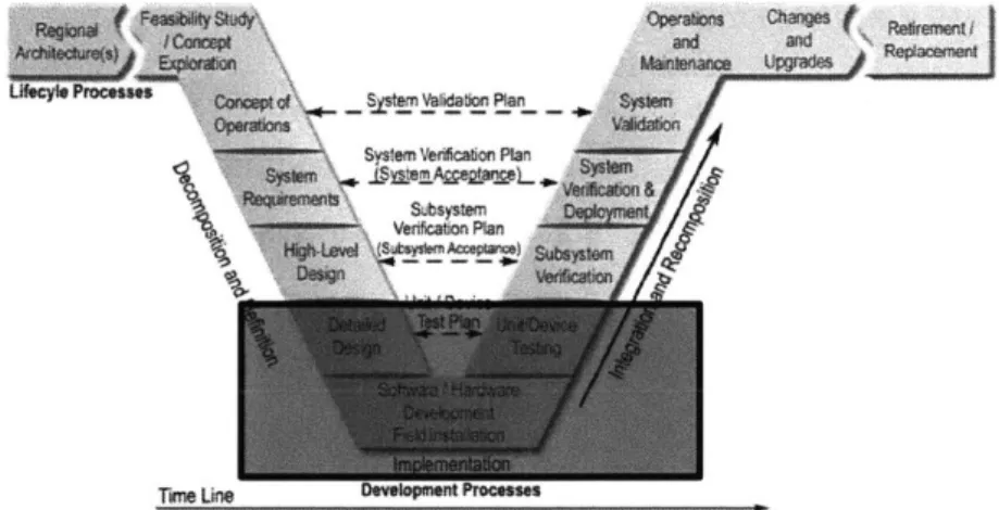
FIGURE 5: REPRESENTATION OF ANTICIPATED COMMONALITY LEVELS OVER PROGRAM LIFECYCLE [1 ] ... 3 4 FIGURE 6: THE V MODEL OF SYSTEMS ENGINEERING [8] ... 39
FIGURE 7: THE MID-V MODEL OF SYSTEMS ENGINEERING ... 40
FIGURE 8: CS REUSE PROCESS DEFINED IN THE SEMP ... 42
FIGURE 9: REPRESENTATIVE ORG CHART FOR SLS CS... 46
FIGURE 10: TIMELINE OF NASA MANNED SPACEFLIGHT SYSTEMS... 49
FIGURE 11: BOM STUDY OF THE LEVEL OF REUSE ON THE CORE STAGE OVER THE PROGRAM L IFE C Y C L E ... 5 1 FIGURE 12: CHANGES IN THE CS MPS OVER THE PROGRAM LIFECYCLE ... 54
FIGURE 13: TOTAL PROGRAM CHANGES IN THE CS OVER THE PROGRAM LIFECYCLE ... 56
FIGURE 14: C S FLOW D SM ... 58
FIGURE 15: CS STRUCTURAL D SM ... 59
FIGURE 16: LIFECYCLE OFFSETS BETWEEN THE EUS, CS AND DELTA IV ... 66
FIGURE 17: EU S FLOW -BASED D SM ... 68
FIGURE 18: EU S STRUCTURAL D SM ... 69
List of Tables
TABLE 1: THE BENEFITS OF REUSE AND COMMONALITY ON COST, SCHEDULE AND RISK VARY FOR THE LEADING AND LAGGING VARIANTS IN A PRODUCT FAMILY. ... 27
TABLE 2: THE PENALTIES OF REUSE AND COMMONALITY ON COST, CAPABILITY AND PERFORMANCE VARY FOR THE LEADING AND LAGGING VARIANTS IN A PRODUCT FAMILY. ... 28
TABLE 3: COMPARING THE BENEFITS OF THE CS REUSE STRATEGY TO A STANDARD REUSE
STRA TEG Y ... 38
TABLE 4: NUMBER OF INTERVIEWEES ORGANIZED BY LEVEL OF AUTHORITY... 45
TABLE 5: COMPARING THE BENEFITS OF COMMONALITIES STRATEGIES, THEORETICAL AND IN PRACTICE ON THE SLS CS AND EUS... 67
1
Introduction
Developing a complex product requires many decisions to be made to satisfy competing goals: cost, schedule, performance, and risk position, to name a few. Decades of development of complex systems have shown that it is difficult to satisfy all of these goals simultaneously. In turn the goals must be prioritized. In order to aid decision makers in this prioritization, various strategies have been developed, one of which is the reuse of assets from existing products in the creation of new products. Reuse promises the benefits of decreased costs and a shortened schedule, as there is no need to invest the capital or the development time to create a new asset. Additionally, the product risk is lower, as known assets present a higher likelihood of success due to operational experience. This strategy has been applied in many industries, from power tools to cars to airplanes [1], in the form of commonality, or the sharing of components amongst members of a product family. However little research exists related to the reuse of assets in the creation of space launch vehicles.
Launch vehicle hardware is traditionally very expensive because it is required to operate in harsh environments (e.g. high g-loads, extreme temperatures, ambient and vacuum pressure) with high reliability. Given this challenge, most launch vehicle components are built to execute a specific mission on a single platform, and are designed and operated accordingly. In turn very few components are used across product platforms. Each new launch vehicle development program tends to incur extremely high non-recurring engineering costs in order to develop an entirely new set of components. These high costs are often accompanied by long development cycles, with significant work that must be done to buy down risk. It seems that the reuse of hardware across products could combat these challenges: lowering non-recurring costs, shortening the schedule and decreasing risk. The question stands: is there something inherently unique about launch vehicle design that prevents or limits reuse? And if not are there strategies that can be
implemented to enforce component reuse during launch vehicle design? These questions form the topic of this thesis.
1.1 Thesis Objective
Most recently an attempt was made to implement reuse during the development of a new launch vehicle, the Space Launch System (SLS), owned by the National Aeronautics and Space
Administration (NASA)1. With limited funds set aside for NASA in the coming years, the budget for SLS is quite constrained and is also limited year-over-year. This limited budget drove NASA to select a vehicle architecture built around reusing designs from past launch vehicles. This reuse
strategy was adopted by the Boeing Company, the prime contractor for the Core Stage (CS) of SLS, who planned to reuse many of the component designs and technologies developed for previous launch vehicles in their CS design.
However, as the vehicle design matured, much of this planned reuse fell away, commonly referred to as divergence in the literature, leading to increased development costs and a
lengthened schedule. There are many thoughts as to what caused reuse to diminish on the SLS CS. This thesis aims to move from speculation to data-driven reasoning to explain this
divergence as well as provide insight into possible solutions to prevent it in future launch systems. The goals of this thesis are three-fold:
1) Perform a retrospective case study of the CS to identify, document and understand the problems that arose that caused divergence in the CS.
2) Assess the planned reuse strategy for the Exploration Upper Stage (EUS). Develop alternative strategies to better capture the desired benefits of reuse in this stage.
3) Generalize these strategies such that they can be applied to future launch vehicles in order to bring about the desired benefits of reuse, namely lower cost and a shortened
development schedule.
Each of these objectives taken independently would provide much value to the aerospace industry, however developing them sequentially will allow insights to first be gleaned from the CS, then applied to the EUS and ultimately generalized for future launch vehicle development programs. In turn this thesis should provide value both to the company at which this research was performed as well as the aerospace industry.
1 Reuse will be defined at length in section 3.1. As a brief clarification though, reuse here refers to the repurposing of existing designs in a new application - for example, reusing a valve design
1.2 Project Motivation
This topic arose due to recent work by the Boeing Company on the SLS vehicle, where the Boeing Company built their plan for the CS around reusing component designs from the Space
Shuttle and other launch vehicles. This strategy was in line with the vehicle architecture strategy selected by NASA, reusing a number of expensive, complex components from the Space Shuttle on the SLS vehicle. Reusing components permitted the Boeing Company to deliver a plan that minimized cost and shortened the development schedule. However, the final design incorporates only a small number of reused component designs. The objective of this thesis is to understand what happened from the original project plan to present day that caused this divergence, and then to develop strategies to combat this divergence from occurring so as to capture the desired
benefits of reuse in the future.
Ultimately this project comes out of a need for prime contractors of space exploration programs to find ways to provide a higher performance product at a lower cost. The aerospace industry is becoming increasingly competitive year after year, with new market players and a more cost-conscious consumer. To remain competitive in this ever-changing market, costs must be lowered with no impact on performance or reliability. Specifically, in the case of human space
exploration, there is no option to reduce cost if this leads to a decrease in the system reliability. When flying human crews, safety is of utmost importance. In turn most hardware for human space exploration missions is designed to be highly fault tolerant, resulting in expensive and slow development cycles. Reuse and commonality have been utilized in other industries to achieve lower costs while also providing shorter product development cycles and more robust products. The question remains as to whether these strategies, when applied to launch vehicles, will result in the gains needed to continue to advance the extent and pursuit of human space exploration.
1.3 Approach and Methodology
To develop a strategy for component reuse on space launch vehicles, the current state must first be understood. For this project, the current state is represented by a case study of the CS of SLS. The study begins with a series of informal interviews conducted to develop an understanding of the situation at hand. A wide array of individuals with varying levels of responsibility and
functional backgrounds are interviewed. From these interviews valuable insight is gained into the challenges encountered when implementing reuse, and an appropriate scope at which to perform this research is defined. The scope is narrowed from reuse throughout the CS to specifically
focusing on reuse within the Main Propulsion System (MPS). Next a literature review is
conducted to gain insight into academic work and best practices done to date on this topic. This is accompanied by an internal document review 1) to gain familiarity with the MPS and 2) to establish the program's reuse strategy.
With this background knowledge in place, the quest for a data-driven assessment of reuse begins. First a detailed time study of industry products, specifically launch vehicles, is performed. Next a bill of materials (BOM) analysis of the CS demonstrates divergence, while also quantifying reuse levels throughout the program. This BOM analysis coupled with important program milestones identifies potential sources of divergence. The sources of divergence are further considered by a study of change propagation in the program. Next the CS architecture is mapped using Design Structure Matrices (DSM), which allows for identification of significant system interactions. These interactions are used to understand how changes in one subsystem may drive divergence in another.
These analyses taken together offer an understanding of the sources of divergence on the CS and lessons learned are developed. Next a study of the EUS reuse strategy occurs, using similar methods to those applied to the CS where possible. The lessons learned from the CS are applied to the reuse plan of the EUS to improve the likelihood of achieving the benefits of reuse on the
EUS. Finally, generalization of these lessons learned allows for development of a plan to improve the chances of realizing the desired benefits of reuse in future launch vehicles.
1.4 Major Findings
Through a retrospective case study of the CS and a prospective case study of the EUS, the answer to the first question posed by this thesis is answered: yes, there are unique aspects of launch vehicles that prevent direct reuse of designs from previous launch vehicles. A range of arguments will support this finding. The first is that lifecycle offsets in launch vehicles are too significant to support reuse. Launch vehicles are offset by decades, which poses a huge challenge
to reuse due to obsolescence of technology, processes, and supply chains. Furthermore,
architecture choices made from one vehicle to the next are likely to shift due to differing mission needs from reliability to performance to cost to schedule. These choices are even further
impacted when considering manned versus unmanned systems. All of these factors come together to bring about architecture changes, which result in changing requirements that inhibit reuse.
Although the successful implementation of reuse in launch vehicles is challenging, there are opportunities to employ similar strategies, such as commonality, to launch vehicles to support the goals afforded by reuse. Rather than focusing on the direct reuse of old hardware designs in new launch vehicles, this thesis argues that programs should focus on developing commonality within a launch vehicle itself. By viewing a launch vehicle as a family of products, with each stage being a single product in the family, the concept of commonality can be applied at the vehicle level. Furthermore, launch vehicles often include plans to expand capability over time. Advanced iterations of the vehicle fill the role of additional products in the family. By applying a commonality strategy at the vehicle level, the desired benefits of reuse can be achieved without requiring the use of heritage component designs. However, it should be noted that even at the vehicle level, implementing commonality might prove challenging if the stages of the vehicle are being designed and built by different contractors, as is often the case in government-funded programs. In turn, it cannot be said that in all cases commonality applied at the launch vehicle level will be successful. Rather, the approach to commonality should be customized for each program, taking into account the various factors that play into the success of said strategy.
Employing a commonality strategy offers the potential benefits promised by a reuse strategy. However, there will still be challenges in implementation. Specifically, attention must be given to planning for future products. Commonality will not occur naturally. If the first product is developed without thought as to the needs of the second product, it is extremely unlikely that components will be shareable between the two. Concerted efforts must be placed on planning for commonality from the program outset. In addition, commonality must be identified as a critical success metric. The program must build its baseline around the commonality strategy in order to incentivize individual decisions to support reuse. If commonality is not fully committed to from
the program outset, it is unlikely that it will be successfully employed in later portions of a program.
This thesis aims to support an argument for pursuing (proactive) commonality as opposed to (reactive) reuse when it comes to new launch vehicle development. It builds upon prior work performed in the areas of reuse and commonality in complex systems, and offers value to future designers of complex systems with large offsets as they aim to develop new products at lower costs with shortened schedules and higher reliability.
1.5 Thesis Roadmap
This thesis mirrors the research approach taken over the course of this project. Chapter 2 provides a brief background on the industry, the project sponsor, the launch vehicle, and the reuse approach to date. A literature review in Chapter 3 will present past work relevant to the topics of reuse, commonality, and complex system design. From these academic sources a solution framework is proposed in Chapter 4. This framework leads directly into the first case study, detailed in Chapter 5, in which the SLS CS reuse strategy is analyzed. The SLS CS offers a rich study of the challenges faced when employing reuse in a space launch vehicle, with findings built around interviews, a time study, a bill of materials analysis, and architecture mapping. These findings are then coupled with organizational context and challenges to develop lessons learned. Next a case study of the SLS EUS, currently in earlier phases of development than the CS, is presented in Chapter 6. The EUS team is working to employ a three-pronged reuse strategy, and the challenges and lessons learned from this strategy are discussed. Finally results, recommendations, and future research opportunities round out this thesis in Chapter 7.
2 Background
This chapter will set the stage for the research topic at hand, beginning with a discussion of the space industry, and more specifically The Boeing Company's position in the industry. This will be followed by a discussion of the SLS vehicle, architecture and missions, as well as The Boeing
Company's involvement in the SLS program. Finally, a discussion of the role of reuse in the SLS vehicle will wrap up the chapter.
2.1 Industry Overview
The human space launch industry began during the Cold War when the Soviet Union and the United States engaged in a space race to put the first human into orbit. NASA built a series of launch vehicles during the 1950's and 1960's, ultimately culminating with the first manned landing on the Moon in 1969, carried by the mighty Saturn V. From 1981 to 2011 NASA focused its efforts on missions to low earth orbit (LEO) by operating the Space Shuttle, first for purely exploration purposes, and then starting in 1998 to support the transport of American astronauts and cargo to and from the International Space Station.
After nearly 70 years of American leadership in human space exploration, significant changes hit NASA in 2010: the Space Shuttle was retired and NASA's Constellation Program was canceled. This left the United States fully dependent upon Russia to shuttle astronauts to and from the International Space Station. At this inflection point, NASA took a step to diversify its investment in human space travel. Through the Commercial Orbital Transportation Services and
Commercial Crew Development contracts, NASA provided funding to commercial companies to aid in developing the private spaceflight sector, ultimately hoping to commercialize transport of both humans and cargo to and from LEO. NASA also began development of a deep space vehicle, the SLS, and a corresponding crew capsule, the Multi Purpose Crew Vehicle, to support human exploration beyond-earth-orbit.
2.2 The Boeing Company
The Boeing Company is the world's largest aerospace company, manufacturing commercial airplanes as well as defense, space and security systems. The Boeing Company is made up of
five business units: Commercial Airplanes; Defense, Space & Security; Capital Corporation; Shared Services Group; and Engineering, Operations and Technology.
Boeing Defense, Space & Security is a global organization headquartered in St. Louis, Missouri that provides solutions in the fields of military fixed-wing aircraft, rotorcraft, satellite systems, launch vehicles, and weapons. Boeing Defense, Space & Security is divided into five business units: Military Aircraft, Global Services and Support, Network and Space Systems, Phantom Works, and Development. Boeing Defense, Space & Security is also involved in United Launch Alliance (ULA), a joint venture with Lockheed Martin to provide reliable, cost-effective launch services to the United States government.
The Boeing Company has been involved in human space exploration since the dawn of the space race, when McDonnell Aircraft Corporation was selected to design, test and build the Mercury
capsule, NASA's first manned spacecraft. With over 50 years of space industry expertise, The Boeing Company was selected as one of the primes for the development of SLS. This work is being spearheaded at the Boeing Defense, Space & Security facility in Huntsville, AL, where the research for this thesis was performed.
2.3 NASA's Space Launch System
SLS will be the world's most powerful launch vehicle when completed, providing capability for the launch of astronauts and payloads into deep space. The SLS vehicle is an evolvable launch vehicle, meaning its capabilities can be expanded over time with additional engineering
resources. This evolvable nature was chosen to support NASA's future goals for deep-space missions. These versions of SLS are referred to as blocks, with the current planned blocks shown in Figure 1. The first block (known as Block 1) is currently being produced and is targeted to first launch in 2018.
322 ft 364 ft 327 ft
SUniversal
Stage Adapter Cargo Fakring
Exploration Exploraftion Upper stage Uppe stage
* Interstage Interstage
core stage Core Stage Core Stage
4. Solid ASoalie
Rockvet Rooltat~n~e
Boosters Boosters
I ri Alk 4.z"a n RS-25 Engines
SLS Block I SLS Block 1B Crew SLS Block 1B Cargo
Figure 1: The Evolution of the Space Launch System [2]
365 ft
SLS Block 2 Cargo
2.4 The Boeing Company and the SLS Program
SLS is composed of various systems procured from multiple suppliers. Figure 2 displays the Block 1 vehicle divided into its various systems.
Launch Abort Syst m
Orion Spacecraft Adapterr
Interim Cryogenic Propulsion Stage
'Aa*\\4O
Orion Multi-Purpose Crew Vehicle Solid Rocket Boosters
Launch Vehicle
Stage Adapter Core Stage
RS-25
Engines (4)
Figure 2: Expanded View of the Space Launch System [2]
Launoh Abort Syste"I Orion Multi-purpos crew WhicI Launch Vehc Stage Adpt.
The Boeing Company is the prime contractor for the design, development, test and production of the vehicle's avionics suite and the cryogenic stages: the CS, the Interim Cryogenic Propulsion
Stage, and the EUS.
The Critical Design Review for the CS is complete and the team is moving towards vehicle build and integration. A significant percentage of the hardware needed for the first build has been procured and is in the process of being assembled and tested at the component level.
The EUS, which also forms a critical part of this research project, has recently passed through Preliminary Design Review (PDR), and is moving to detailed design and analysis.
2.5
Reuse Efforts on SLS
The architecture of SLS was built on reusing critical pieces of hardware and technology from previous launch vehicles, including the Space Shuttle, to reduce development time and cost. Although the practice of reuse and commonality is common in other industries, it is rarely employed in aerospace. Yet for the SLS vehicle, reuse was viewed as an absolute necessity due to a severely restricted budget. Compared to the approximate $141.5 billion spent to develop the Space Shuttle [3], NASA had a budget of just $7.1 billion for SLS [4]2. To best utilize this budget, NASA focused reuse on the core technologies that are most costly to develop: the propulsion systems. The SLS will reuse:
1) The Space Shuttle Main Engines (RS-25D) as the main engines of the SLS Core Stage 2) Space Shuttle-derived solid launch vehicle boosters as the SLS solid launch vehicle
boosters (growth from 4 segments to 5)
3) ULA's Delta IV Cryogenic Second Stage as the SLS Block 1 upper stage 4) ULA's Delta IV Second Stage Engines (RLlO) as the EUS main engines
These reuse choices determined much of the architecture for the vehicle, setting the vehicle size and power level.
Given NASA's choice to prioritize reuse, it was natural for the Boeing Company to match NASA's architecture by proposing to build the CS around significant design reuse. The CS is composed of many different subsystems (e.g. propulsion, avionics, and structures), each of which is required to perform specific functions. Two subsystems in particular, the Main
Propulsion System (MPS) and the Thrust Vector Control System (TVC) are strongly tied to the main engines. The primary function of the MPS is to support the flow of fluids from the
propellant tanks to the engines, resulting in component-level requirements that are strongly tied to the needs of the engines they support. The TVC system is used to control the positioning of the engines relative to the vehicle centerline, permitting the thrust to be vectored to control the flight of the launch vehicle. In turn, the TVC system design is closely coupled to the main engines so many components of the TVC subsystem were identified as reuse candidates. These two subsystems represent a significant percentage of the planned reuse proposed by the Boeing Company when developing the CS development plan.
3 Literature Review
This literature review section will provide a brief discussion of prior academic work performed related to reuse and commonality. First reuse and commonality will be defined followed by a discussion of the benefits and penalties of both strategies. Two critical topics found in previous research which influence reuse, divergence and lifecycle offsets, will be considered and
analytical tools to allow for their identification will be developed. A discussion of management techniques that have successfully supported reuse and commonality will round out this chapter.
3.1 Defining Reuse and Commonality
The term "reuse" can mean many different things, and thus it seems worthwhile to spend a bit of time defining this term. Below are definitions for the three types of reuse that will be discussed
in this thesis:
1) Hardware Reuse: physical reuse of existing hardware (e.g. taking a piece of hardware that is already built and repurposing it for a new application)
2) Design Reuse: reuse of an existing hardware design (e.g. making a new part with a new serial number from an existing drawing for use in a new application)
3) Derived Reuse: modified reuse of an existing hardware design (e.g. modifying a drawing and using the modified design in a new application)
The SLS CS includes all three of these reuse types, however the most common type discussed in this thesis is design reuse, which will be referred to henceforth as "reuse." Any deviation from design reuse will be referred to by name.
Another term used throughout this thesis is commonality, or the sharing of assets across a product family. To explain the difference between commonality and reuse, consider the
lifecycles of two products, product A and product B. In the case where product A and product B are being developed concurrently, commonality is a strategy employed to utilize common assets between these two products to realize an economic benefit. Commonality requires considering the needs of both products simultaneously, and developing assets to satisfy these needs. In contrast consider the case where product A is developed before product B, and assets from product A are identified for use in product B retroactively. Reuse represents the repurposing of these assets from product A to realize an economic benefit for product B. In reuse no initial
thought is given to designing assets to benefit both products. Instead product B retroactively identifies beneficial assets from product A. Product A gains to benefit from reuse. In contrast commonality benefits both products.
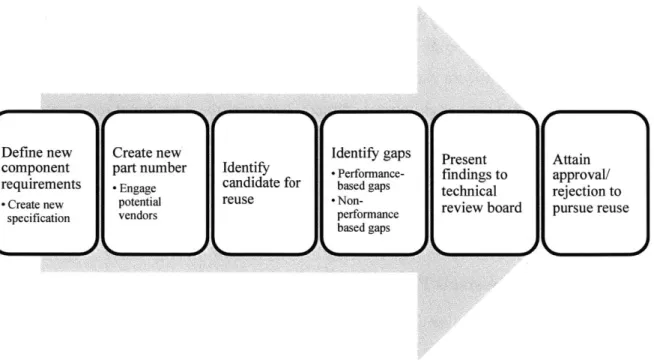
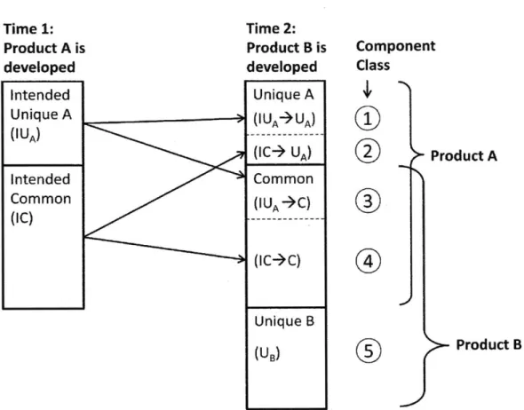
Boas developed a classification system, shown in Figure 3, to define reuse classes for a program in which two products are developed sequentially (product A followed by product B). During the development of product A, some parts were identified as unique to product A while others were intended to be common with product B. During the development of product B, five unique component classes were found. Class 1 represents parts that were intended unique to product A
and remained unique. Class 2 represents parts that were intended to be common but were only used in product A. Class 3 represents parts that were intended to be unique to product A, but were actually used in both products. In turn class 3 best aligns with the definition of reuse as given in the first chapter of this section: reuse which was reactive. Class 4 represents parts that were intended to be common and were common. This class represents commonality as discussed in the previous paragraph: proactive reuse planned from the outset of development. Class 5
represents the unique parts designed solely for product B. Understanding these classifications aids in understanding the differences between reuse and commonality.
Time 1: Product A is developed Intended Unique A (IUA) Intended Common (IC) Component Class Time 2: Product B is developed Unique A (IUA A) ---(IC-- UA) Common (IUA9C) ---(IC->C) Unique B (UB) I I
Figure 3: Reuse Classification System as Defined
0
0
Another definition of reuse that is currently quite common in the launch vehicle industry is the reuse of an entire launch vehicle or stage. For example the Space Shuttle was built as a reusable vehicle: it would deliver its payload to LEO and then return to earth for refurbishment prior to its next launch. Several private companies are currently pursuing stage reuse, where the first stage of the launch vehicle is returning to Earth after delivering its payload to be used again for another launch. Although stage and vehicle reuse is an extremely interesting topic, it is not the focus of this thesis. For the purpose of this thesis "reuse" refers not to vehicle reuse, but to hardware, design, or derived reuse as defined above.
Now that these critical terms have been defined, the benefits and penalties of commonality and reuse will be discussed.
3.2 Benefits and Penalties of Shared Assets
Prior research identifies both benefits and penalties of sharing assets between products, whether through reuse or commonality. Consider two products developed in series: the first product is
Product A
Product B
defined as product A and latter products as product B. A detailed discussion of the benefits and penalties of shared assets on the product lifecycles of products A and B follows, and is critical to understanding the rationale behind employing reuse and commonality strategies in complex system development.
3.2.1 Benefits
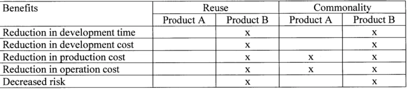
The benefits of reuse and commonality improve the cost, schedule and risk positions of a program, discussed below. A summary of these benefits is given in
Table 1, which highlights that product B potentially realizes the vast majority of the benefits from reuse and commonality with product A benefiting only from commonality.
1) Reduction in development time
When developing product B, sharing assets from product A will shorten product B's development timeline. Utilizing an asset that has already been developed and tested drastically reduces the time required to prepare that asset for integration with its parent system. In turn sharing assets decreases time to market, an important factor for successful product introduction [5].
2) Reduction in development, production, and operation costs
Product B also benefits from reduced development cost, when utilizing assets developed for product A. For any existing asset used by product B, there is a reduction in the labor hours spent on development, which reduces development cost [5]. Costs are further reduced during production. Assuming that product A and product B are produced simultaneously, utilizing common assets between the two systems brings about
economies of scale [6]. This reduces production costs for both product A and product B on a per unit basis by spreading fixed costs across a higher volume of components. There can also be improved learning curve effects. Operation costs are also reduced for both product A and product B. By lowering the number of different types of assets required to build any given set of products, lower costs in inventory, materials management,
logistics, and purchasing are achieved [5].
Pre-existing assets also lower risk compared to developing all new assets. Assets that have been successfully demonstrated in product A provide greater confidence when utilized in product B. Critical to this thesis specifically, hardware demonstrated in space carries a higher technology readiness level (TRL), an important metric in evaluating risk for NASA systems. Utilizing assets that have high TRL's increases confidence in the
system's likelihood of success.
Table 1: The benefits of reuse and commonality on cost, schedule and risk vary for the leading and lagging variants in a product family.
Benefits Reuse Commonality
Product A Product B Product A Product B
Reduction in development time x x
Reduction in development cost x x
Reduction in production cost x x x
Reduction in operation cost x x x
Decreased risk x x
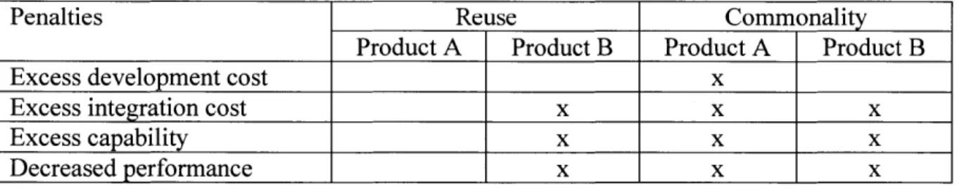
3.2.2 Penalties
The penalties of reuse and commonality impact the cost, capability and performance of a program, discussed below. Table 2 provides a summary of these penalties, highlighting that product B is negatively impacted by both strategies with product A only penalized by commonality.
1) Excess development and integration cost
When utilizing an asset from product A into product B, whether through commonality or reuse, there will be increased costs in either development or integration. When a
common part is design, product A will incur greater development costs than if it developed an asset to only meet its own needs. A common asset will generally have a larger number of requirements to satisfy both products. This will increase complexity leading to increased development costs, adding to the total program cost of Product A. Product B will in turn be less costly, resulting in a lower productfamily cost. However, product A must carry the excess cost initially. In the case of reuse, gaps will exist
and allow for successful integration into product B, additional analysis or testing will be required, resulting in increased integration costs, likely to impact both products.
2) Excess capability
Developing a common asset or reusing an asset will result in excess capability in the products [5], depending on the difference in levels of performance of the two (or more) products. In the case of a common asset, the asset must meet the requirements of both products simultaneously (the union), resulting in some amount of excess capability for both products. In contrast when reusing an asset, product B may carry the excess
capability penalty as there may be functionality in the asset required for product A that is not needed for product B.
3) Decreased performance
Because common or reused assets carry excess capability, product performance will be decreased. This penalty is especially pertinent in the case of launch vehicles, where vehicle mass is one of the primary figures of merit. Any excess capability in performance that results in increased component mass will negatively impact vehicle mass and
therefore vehicle performance.
Table 2: The penalties of reuse and commonality on cost, capability and performance vary for the
leading and lagging variants in a product family.
Penalties Reuse Commonality
Product A Product B Product A Product B
Excess development cost x
Excess integration cost x x x
-Excess capability x x x
Decreased performance x x x
This discussion of the benefits and penalties of reuse and commonality provide some insight into why a program may choose to pursue one strategy versus the other. A challenge remains in quantifying whether the benefits of each of these strategies outweigh the penalties for any given product. In the case of the SLS CS it was determined early on that reuse offered sufficient benefit to outweigh the penalties, resulting in the selection of that strategy by the program. To determine whether or not that assessment was correct, further academic methods for assessing reuse are discussed below.
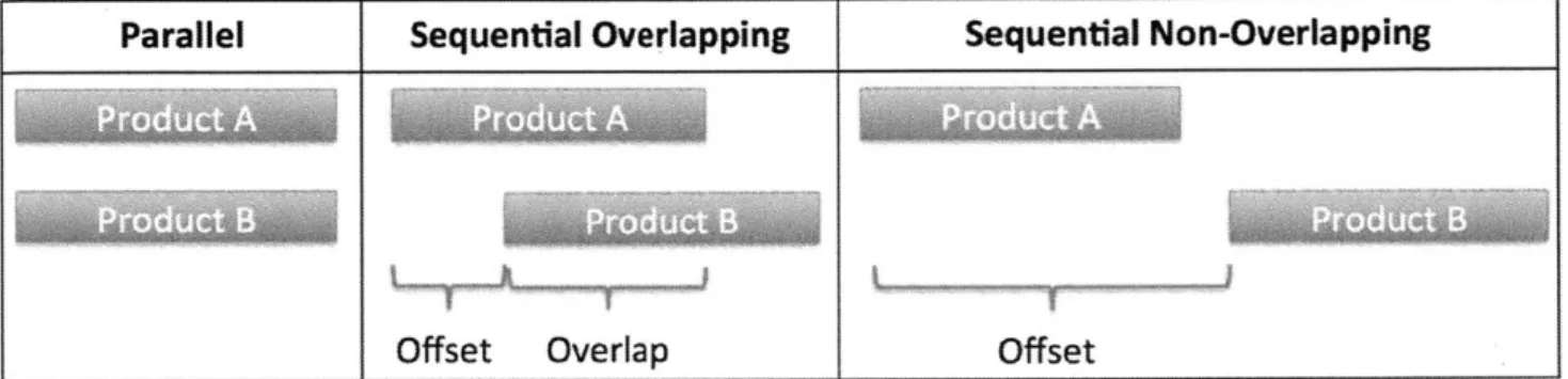
3.3 Lifecycle Offsets
Lifecycle offsets refer to the temporal relationships that exist between the lifecycle phases of different products [1]. Research by Boas on the relationship between lifecycle offsets and reuse found the degree of offset to be critical to the successful implementation of reuse. The three offset classifications utilized by Boas were parallel, sequential overlapping, and sequential non-overlapping. Figure 4 graphically presents these offsets. Product A is known as the lead variant and product B as the latter variant.
Parallel Sequential Overlapping Sequential Non-Overlapping
Offset Overlap Offset
Figure 4: Three Types of Offsets as Studied by Boas
Boas found that parallel development offers the highest likelihood for successful implementation of commonality. Developing products simultaneously leads to the creation of decision-making processes that capture the most benefit for the product family. By realizing commonality at the product family level, the optimal solution for the family can be identified bringing about the maximum benefit to the program.
As product families move from parallel development towards sequential, lifecycle offsets present increasing challenges due in part to a lack of knowledge of the needs of latter variants during the development of the lead product. This results in choices being made to maximize the economics of the lead variant, rather than those of the product family. Lifecycle offsets further weaken the product family, as spans in time are accompanied by changes in technology and product
obsolescence. As technology changes or products become obsolete, there may be a benefit for the latter variant to elect a new process or component in order to realize economic benefits. This may improve the economics of the latter variant but can hurt that of the lead and the product family, which benefits from commonality. The larger the lifecycle offset between products, the
more challenging it is to capture the economic benefits of commonality within the product family.
As we approach the topic of reuse in a space launch vehicle context, understanding lifecycle offsets will be critical to assessing reuse as a strategy to lower costs, shorten schedules and decrease risk.
3.4 Divergence Theory
Divergence is a concept that states that commonality in a platform tends to decrease throughout the product lifecycle, for both beneficial and non-beneficial reasons [1]. Boas performed case
studies on seven different product families, ranging from military aircraft to printing presses to semiconductor manufacturing equipment. Through these studies, four types of changes were identified as common sources of divergence: changing requirements; learning; availability of new technologies; and component obsolescence [1]. It was also found that divergence is triggered by an enabler, either an economic incentive or a lack of coordination [1].
When developing a new product, it would be ideal if requirements could be fully defined at the project's outset and held constant throughout. This would allow for a linear product development process, foregoing any churn due to changing requirements. However, requirements do change over the lifecycle of a program, resulting in an iterative process. These iterations can drive divergence, as any requirement change should be accompanied by an assessment of alternative solutions, bringing about an opportunity to select an alternative and drive a decrease in
commonality.
Learning is another common source of divergence, as there is a tendency for additional knowledge gained during production and operations to drive design modifications for later instances (or block upgrades) of the product. As a design moves through its lifecycle, challenges will be faced and counter-measures developed. These solutions can result in changes to the design and divergence in the system. For example consider a system in which the same
component is used in two locations. During the operations phase of the product, it is found that one of these locations (A) tends to require more frequent maintenance than does the other (B). It
would be beneficial for A's design to be altered to support removal for maintenance. However B's design fits its needs and should remain unchanged. A new part may then replace A, with B unchanged, driving divergence in the system
The final two change sources identified by Boas, availability of new technologies and obsolescence, are related in many ways to lifecycle offsets, discussed above, so no further discussion will take place here.
Each of these sources of change may result in divergence; however an enabler must exist to trigger divergence, often either an economic incentive or a lack of coordination [1]. In certain cases elimination of a common component leads to an economic incentive, thereby resulting in a beneficial form of divergence. In these cases, the change from common to unique results in a more profitable product family and in turn is an acceptable form of divergence. However there are also cases where the main enabler of divergence is a lack of coordination. In these cases divergence is non-beneficial and should be avoided. Greater care to the incentive structure and the decision making process should be given to prevent non-beneficial divergence.
As we move through the case study of the SLS CS and on to the course of action for EUS, it is critical to recall that divergence can be both beneficial and non-beneficial. All divergence should not be viewed as a "negative." Rather the sources and enablers of divergence must be understood in order to classify divergence and to develop appropriate solutions to counter non-beneficial divergence.
3.5 Management Techniques to Commonality and Reuse
Much research has been done to identify management techniques that result in the successful implementation of commonality and reuse. A study related to the development of the Sony Walkman highlights the importance of management's commitment to commonality. Boas also developed a large number of management recommendations during his multi-industry
When considering the development of the Sony Walkman product family, Sanderson and Uzumeri found several aspects of management that led to Sony's command of the personal portable stereo market [7]. The first was the commitment of management to minimize design cost. In an industry with a multitude of customer demands, Sony kept cost at the core of its product strategy. This led to the development of product modules and platforms. By requiring engineers to design new products around existing platforms, Sony was able to produce a wide variety of models with high cost and quality. This management strategy maintained commonality and discouraged divergence.
Boas also identified a number of management approaches to capture the benefits of commonality:
1) Commonality will not occur accidentally. The identification of opportunities for
commonality must be managed proactively. Formal ownership of commonality should be established to ensure that opportunities for commonality are identified.
2) Commonality can be beneficial or detrimental and should not be blindly implemented. Instead a detailed evaluation of each opportunity for commonality should determine the proper course of action.
3) Once commonality is identified as beneficial, ensure that it is implemented. This may require metrics to support reuse, but at a minimum requires the creation of processes that ensure changes are evaluated in terms of their impact on commonality.
These proven management techniques will help guide later discussions related to successful implementation of reuse and commonality in launch vehicles.
4 Proposed Framework
-
Analysis Approach
The analytical approach of this thesis is built upon three unique assessments. The first is a study of the lifecycle offsets relevant to the SLS stages. A bill of materials analysis will measure reuse levels throughout the program lifecycle. The expectation is that reuse levels will peak during the early planning phases of the program and will decrease thereafter, showing divergence as defined by the literature. Finally, design structure matrices (DSM) will map the subsystem interactions within each of these stages. These matrices provide insight into dependencies within each stage, and when coupled with changes may lead to divergence in the system.
4.1 Divergence Demonstrated via Lifecycle Offsets
The first step in developing a reuse strategy is to understand the temporal offsets between the products being considered. In the case of launch vehicles, it is useful to consider offsets both between different NASA-developed launch vehicles as well as between the stages of a single vehicle. Launch vehicles are developed infrequently, with lifecycles on the order of decades. In turn we are likely to see very large offsets between the development timelines of two
independent vehicles (e.g. the Space Shuttle and SLS). However, most launch vehicles are composed of multiple stages in order to complete the mission, and in turn the stages tend to be developed sequentially with some overlap. Considering the lifecycle offsets at the vehicle and stage level may provide insight into similarities and differences in the challenges faced when attempting to reuse designs across these platforms.
4.2 Divergence Quantified through a Bill of Materials Analysis
The literature has demonstrated that as the development of a complex system progresses it is typical to observe a decrease in commonality levels, referred to as divergence. Through initial interviews it is quite clear that the SLS CS has undergone significant divergence, however no formal analysis has identified the root cause. In turn a BOM analysis of the CS was performed to identify trends in reuse over time. By mapping these trends to key program dates and considering trends in change management data, insight into the sources of divergence was developed.
Prior to performing a BOM analysis on the CS, it is important to understand what a typical BOM analysis of commonality looks like. A BOM analysis results in a graphical representation of the
success (or failure) at incorporating reuse into a design. Boas proposed Figure 5 as a
representative graph of commonality over program lifecycle. The x and y axes represent time and percent common parts, respectively. This model proposes maximum reuse levels occurring near the start of the program, during the planning phases when optimism about the successful implementation of reuse is highest. At the outset of the program commonality levels are expected to increase rapidly, due to limited knowledge as to the true feasibility of reuse. Point A
represents the peak of this planning phase. From this point, divergence occurs resulting in ever decreasing levels of reuse as the program matures. The sources of divergence discussed in section 3.4 drive this decrease. Point B, although not commonly observed in Boas' studies, represents a potential mid-project attempt to increase reuse levels after significant divergence has occurred. These attempts aim to reincorporate reuse into a program late in the game with a hope of realizing some of the planned (and lost) economic benefits. Unfortunately, Boas found that late attempts to reestablish reuse in a program were rarely successful.
A 0
E
E
B 0 C C Itime
Figure 5: Representation of Anticipated Commonality Levels over Program Lifecycle [1]
The data for Boas' BOM analysis comes directly from a bill of materials. By comparing part numbers across a family of products, Boas can easily identify shared components in a product. However, in the case of SLS, a standard BOM analysis could not be performed due to the program's position on the use of part numbers versus specifications.
The program chose to create a new specification for every part on the launch vehicle, including the case where a part design was to be reused. Rather than utilizing an existing part number, an entirely new specification and part number were assigned. To indicate the intention for a vendor to reuse a design if possible, the original part number was defined in the text of the specification.
This part number would typically be called out in the item definition/description at the start of the specification. However, it was ultimately up to the vendor to decide how to satisfy that
specification. The vendor was not required to deliver a reused design. The vendor was paid to deliver a part that fully met the specification, which may or may not have been possible with a reused part. In turn tracing heritage part numbers in the CS BOM was impossible.
Instead the BOM analysis data for the CS was pulled from a mix of sources and was used to map out divergence over the life of the program. Proposal data was used to gather an understanding of the initial baseline. This data was then supplemented with information from a risk and
opportunity management tool, which identified any changes to hardware baselines, including reuse over the course of the program. In turn the analysis shows sharper trends than would likely be observed in a true BOM-based analysis due to limited availability of temporal information. Nonetheless this BOM analysis provides interesting insights into the overall trends of reuse in the program, which will be discussed in Section 5.5.
4.3 System Architecture Mapping through Design Structure Matrices Commonality is ultimately tied to product architecture. There are a variety of ways to map the architecture of a system. One possible tool is a DSM, which provides a clear and compact representation of the interfaces and interactions that exist within a system. Given the
complexities in the design of the CS, developing a DSM to map the existing connections was the next step in the system analysis.
DSM's can be constructed at different levels of abstraction, from the individual component level to subsystems to systems. For this thesis DSM's were developed at the subsystem level. The reasons for this choice are as follows:
1) The DSM is meant to serve as a readily digestible map of the system, one that can be used as a communication tool. Performing a component level DSM would result in an
extremely large and complex DSM, making it challenging to use the DSM for communication.
2) Most launch vehicle stages share common subsystems, however the specific interfaces of these subsystems may vary. By modeling at the subsystem level it becomes possible to quickly identify architecture choices that are unique to a certain stage.
3) A sufficient level of granularity is necessary for the DSM to provide meaningful insights. A system level DSM would have ignored the complexity that exists within each of the major systems (i.e. propulsion, structures, avionics).
By analyzing at the subsystem level, it is possible to understand how choices made within a subsystem have impacted the overall system level performance. After developing a DSM of the system, the dependencies between subsystems are identified, bringing about further insight into sources of divergence.
5 Case Study 1 (Retrospective): Core Stage Reuse
A case study of the CS will provide insight into the incorporation of reuse in the SLS vehicle thus far. In order to allow for a thorough analysis to be performed, the decision was made to focus in on the MPS rather than attempting to understand all intended reuse scenarios across the stage. A discussion of NASA's role in the mandating of reuse begins this chapter, followed by the processes developed by the Boeing Company to support reuse in the CS. A summary of information given through interviews will present some of the organizational context surrounding reuse on the CS. Next an analysis of lifecycle offsets will detail the temporal landscape of the CS development with respect to other NASA-funded launch vehicles. A BOM analysis and change management data will highlight periods of divergence in the program. These periods of divergence will lead to the development of architectural mapping data to identify subsystem interactions that drove reuse out of the system. Finally, a discussion of the challenges found and lessons learned will round out the CS case study.
5.1 Setting the Stage: NASA Mandated Reuse
When the Boeing Company developed its development plan for the CS, cost and schedule reigned supreme. NASA needed a cost-effective launch vehicle quickly in order to return the capability of human space exploration to the United States. In turn NASA mandated that the SLS be architected to incorporate significant reuse, both design and hardware reuse, from prior space vehicles, primarily the Space Shuttle and Constellation.
One candidate identified by NASA for hardware reuse was the RS-25D. Launch vehicle engines are extremely costly to develop, requiring years to design, test, and verify. This development schedule is further lengthened when the engine must support human space exploration, with the levying of more stringent requirements. In turn the SLS architecture needed to incorporate an existing launch vehicle engine if the program was to meet its cost and schedule targets. This need combined with the fact that NASA had remaining RS-25D's in storage led to the decision to reuse the RS-25D as the engines for the CS.
This engine selection afforded the Boeing Company the opportunity to further support NASA's cost and schedule goals, creating a low cost stage with a shortened development schedule, by
reusing various pieces of support hardware developed for use with the RS-25D. One example of a component that seemed a likely candidate for reuse was the pre-valve, a valve that isolates the fluid flow path between the propellant tank and the RS-25D. The pre-valve was designed to accommodate specific parameters set by the engine, for example pressure, flow rate and
temperature. Given that the engine was to remain unchanged, it seemed that this valve could be used as-is in the new CS design. This same logic was applied throughout the CS, resulting in a target reuse level of 80% for the MPS. These reused designs offered the two benefits NASA was looking for, decreased cost and a shortened development schedule, as well as the added benefit of lowering risk as flight-tested hardware carries a higher TRL than a new design. The expected benefits of reuse are shown in
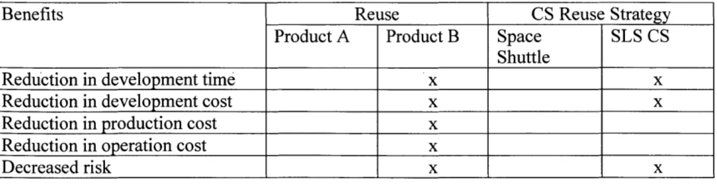
Table 3. Here you can see that the CS reuse strategy realizes only some of the benefits of a standard reuse strategy, in which both products A and B are still in operation. Two areas in which expected benefits are not realized are production and operations. Because Space Shuttle hardware is no longer being actively produced or operated, the CS cannot fully capture the benefits of reuse. Reduction in production costs come about due to economies of scale, as multiple products utilizing the same asset lowers per unit production costs. However in the case of the CS, the Space Shuttle is no longer producing hardware, meaning that economies of scale do not exist. Operational costs, which are reduced in reuse scenarios due to sharing of spares and support equipment between two products, are also left unrealized in the case of the CS. Because the Space Shuttle is no longer in operation, the CS must fully support all operational costs rather than sharing these with the Space Shuttle program.
Table 3: Comparing the benefits of the CS reuse strategy to a standard reuse strategy
Benefits Reuse CS Reuse Strategy
Product A Product B Space SLS CS
Shuttle
Reduction in development time x x
Reduction in development cost x x
Reduction in production cost x
Reduction in operation cost x
![Figure 1: The Evolution of the Space Launch System [2]](https://thumb-eu.123doks.com/thumbv2/123doknet/14725906.571763/20.917.126.718.112.433/figure-evolution-space-launch.webp)
![Figure 5: Representation of Anticipated Commonality Levels over Program Lifecycle [1]](https://thumb-eu.123doks.com/thumbv2/123doknet/14725906.571763/35.918.287.698.509.825/figure-representation-anticipated-commonality-levels-program-lifecycle.webp)
![Figure 6: The V Model of Systems Engineering [8]](https://thumb-eu.123doks.com/thumbv2/123doknet/14725906.571763/40.917.192.714.618.884/figure-v-model-systems-engineering.webp)