HAL Id: hal-01075121
https://hal.archives-ouvertes.fr/hal-01075121
Submitted on 16 Oct 2014
HAL is a multi-disciplinary open access
archive for the deposit and dissemination of
sci-entific research documents, whether they are
pub-lished or not. The documents may come from
teaching and research institutions in France or
abroad, or from public or private research centers.
L’archive ouverte pluridisciplinaire HAL, est
destinée au dépôt et à la diffusion de documents
scientifiques de niveau recherche, publiés ou non,
émanant des établissements d’enseignement et de
recherche français ou étrangers, des laboratoires
publics ou privés.
A UML-based environment for test scenarios in mobile
settings
Pierre André, Hélène Waeselynck, Nicolas Rivière
To cite this version:
Pierre André, Hélène Waeselynck, Nicolas Rivière. A UML-based environment for test scenarios in
mobile settings. 2013 International Conference on Computer, Information and Telecommunication
Systems (CITS), May 2013, Athens, Greece. pp.1 - 5, �10.1109/CITS.2013.6705716�. �hal-01075121�
A UML-Based Environment for Test Scenarios in Mobile Settings
Pierre André
1,2, Hélène Waeselynck
1,2, Nicolas Rivière
1,2 1CNRS, LAAS, 7, Av du Colonel Roche, F-31400 Toulouse, France2Univ de Toulouse, UPS, LAAS, F-31400 Toulouse, France
{Pierre.Andre, Helene.Waeselynck, Nicolas.Riviere}@laas.fr
Abstract—TERMOS is an UML-based formal language for specifying scenarios in mobile computing systems. TERMOS scenarios are used for the verification of test traces: they represent mandatory or forbidden interactions that are searched for in the trace. Building upon previous work on the semantics of TERMOS, this paper presents the complete integration of the language into UML support technology. A TERMOS profile has been developed for the editing of scenarios, as well as an Eclipse plugin for the automated checking of traces. We demonstrate the approach on a case study, a group membership protocol in ad hoc networks.
Keywords- Mobile computing systems, UML sequence diagrams, UML profile, trace analysis.
I. INTRODUCTION
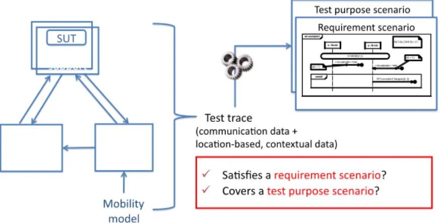
Mobile computing systems involve devices (handset, PDA, laptop, intelligent car, …) that move within some physical areas, while being connected to networks by means of wireless links. Compared to “traditional” distributed systems, such systems execute in an extremely dynamic context. The movement of devices yields an unstable topology of connection. Links with other mobile devices or with infrastructure nodes may be established or destroyed depending on the location. Moreover, mobile nodes may dynamically appear and disappear as devices are switched on and off, run out of power or go to standby. Our work addresses a passive testing approach for such systems. Passive testing (see e.g., [1]) is the process of detecting errors by passively observing the execution trace of a running system. In our case, the properties to be checked are specified using graphical interaction scenarios. Figure 1 gives a schematic view of the approach. The system under test (SUT) is run in a simulated environment, using a synthetic workload. The SUT may involve both fixed nodes and mobile devices. The movement of the latter ones is managed according to some mobility model, a context simulator being in charge of producing location-based data. Execution traces are collected, including both communication messages and location-based data. The traces are then automatically analyzed with respect to predefined scenarios, representing test requirements or test purposes. Test requirements specify mandatory (positive requirement) or forbidden (negative requirement) interactions. Any observed violation of a requirement must be reported. Test purposes specify interactions of interest, which we would like to observe at least once during testing. If the interaction appears in the trace, the test purpose is reported as covered.
The automated checking of the traces against scenarios can only be possible if the scenario language possesses a formal semantics. This led us to design a formal UML-based language called TERMOS (Test Requirement
Language for Mobile Settings). TERMOS is a specialization of UML Sequence Diagrams [2]. Its genesis can be found in our earlier work [3-5]. We first noticed that the spatial configurations of nodes should be a first class concept [3]. As a result, a scenario should have both (i) a spatial view, depicting the dynamically changing topology of nodes as a sequence of graphs, and (ii) an event view representing the communications between nodes. To account for both views, the checking of test traces against scenarios should combine graph matching and event order analysis. Later work defined the graph matching part of the TERMOS semantics [4] and the event order analysis algorithm [5].
While all pieces of TERMOS had been defined, we did not have yet a complete tool chain for the analysis of test traces. This paper reports on recent effort to integrate the TERMOS language and algorithms in an open-source UML environment. We now have a full demonstrator for the approach, from the graphical editing of scenarios to their automated use for checking test traces.
Section II of this paper gives an overview of the TERMOS language. Section III shows how we specialized the Eclipse Papyrus1 environment for the editing of scenarios, by means of a TERMOS UML profile. Section IV presents the Eclipse plugin we implemented for the processing of scenarios. Its use is illustrated on a case study, a group membership protocol (GMP) for ad hoc networks [6]. Section V discusses related work. Section VI concludes.
II. OVERVIEW OF TERMOS
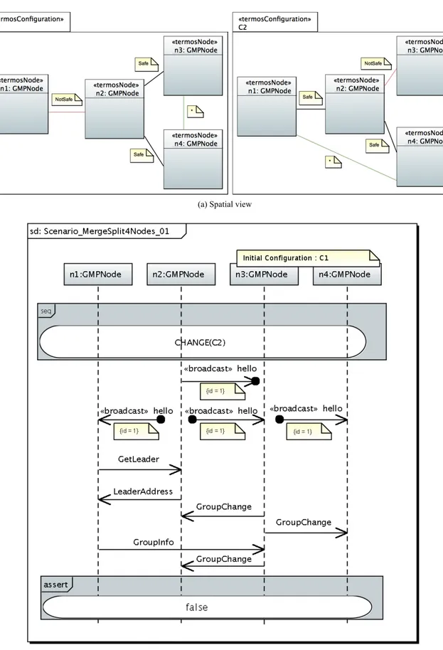
Figure 2 shows an exemplary TERMOS scenario, with its spatial view (Fig. 2.a) and its event view (Fig. 2.b). It is extracted from the GMP case study we performed [6]. In this GMP, groups split and merge according to the location of mobile nodes. The protocol uses the concept of safe distance to determine which nodes should form a group.
The spatial view contains a set of spatial configurations for the nodes of the scenario. We depict them using UML object diagrams, but conceptually they consist of labeled graphs. The modeler chooses the labels that are meaningful for the target application. Edge labels characterize the connection of nodes, while node labels (not shown here) are used for contextual attributes of nodes. In Figure 2.a, nodes can have two types of connection, depending on their distance: Safe and NotSafe. A wildcard ‘*’ may also be used to indicate don’t care connection types.
1
The event view shows the interaction of nodes using a specialization of sequence diagrams. Like in usual sequence diagrams, lifelines are drawn for the nodes and the partial orders of their communications are shown. The TERMOS specifics are:
• an explicit consideration for the successive spatial configurations underlying the communications; • the possibility to represent local broadcast; • some syntactic restrictions to sequence diagrams. The first two specifics are relevant to the mobile setting, while the syntactic restrictions are relevant to the use of TERMOS for checking execution traces.
A TERMOS event view always has an initial configuration, and configuration changes are explicitly depicted as global events. In Figure 2.b, the change from
C1 to C2 is an abstraction for the movement of n2 getting
close to n1 while getting away from n3. All shown messages occur in the new C2 configuration. They correspond to concurrent group operations, a split and a merge, causally related to the change of connection between n2 and the other nodes.
Local broadcast is a classical mode of communication in ad hoc networks. A node sends a message in its vicinity; whoever is at communication range may listen to, and react to, the message. In the GMP example, local broadcast is used for group discovery. When n2 broadcasts its new location in a hello message, the other nodes notice the configuration change and initiate group change operations. Note how a broadcast involves one send event and possibly many receive events. The tagged value attached to them allows us to pair each receive event to the send event that caused it.
A syntactic restriction is to have exactly one assert fragment, at the end of the diagram. Intuitively, everything before assert is a potential interaction, while the content of
assert is mandatory. In Figure 2.b, the assertion is merely a false invariant. As false cannot hold, the scenario
represents a negative requirement: the potential interaction shall never occur. A true assertion would characterize a test purpose to cover: true trivially holds whenever assert is reached, that is, whenever the potential interaction occurred. Richer assert contents, showing interactions with messages, express positive requirements of the form: whenever the potential interaction occurs, then the asserted one must follow.
We interpret TERMOS scenarios as generic patterns, instances of which are searched for in the execution trace. In Figure 2, the nodes ni are symbolic. Any subset of four SUT nodes can match them during execution, by exhibiting the proper spatial configurations and communication events.
The search for scenario instances involves two steps: 1. Determine which physical nodes of the trace
exhibit the sequence of configurations of the scenario, and when they do so.
2. Analyze the order of events in the identified SUT configurations.
SUT configurations can be retrieved from the location-based data. Step 1 then amounts to a graph matching problem: we search for a sequence pattern (coming from the scenario) to appear in a sequence of SUT configurations. We developed a tool, GraphSeq [4], to do the search.
Step 2 requires an interpretation of the event view in terms of partial orders of events. In TERMOS, the chosen semantics encodes the partial orders in a symbolic automaton [5]. Its aim is to categorize trace fragments as valid, invalid or inconclusive with respect to the scenario.
III. AUMLPROFILE FOR EDITING TERMOS SCENARIOS
A profile is a means to customize UML models for a domain. It uses lightweight extension mechanisms like stereotypes, tag values, and OCL constraints. We created a profile for TERMOS scenarios. It involves six stereotypes. Some of them graphically appear in Figure 2. The spatial view contains packages with the <<termosConfiguration>> stereotype, where each configuration involves <<termosNode>> elements and their <<termosConnection>> associations. The sequence diagram of the event view has the <<termosScenario>> stereotype. It may involve <<configChange>> elements, as well as <<broadcast>> messages. Some stereotypes have attributes. For example, any <<termosScenario>> has an initial configuration attribute, which must be a <<termosConfiguration>>. A <<termosConnection>> has a connection label, taking its values from a user-defined enumerated type (e.g., Safe, NotSafe). Also, as explained in the previous section, <<broadcast>> messages have an id tag. !"#$%&'(&)#"%#*"+,(-)% ! .,/#0"#%,%("1'-("2"+$%#*"+,(-)3% ! 4)5"(#%,%$"#$%&'(&)#"%#*"+,(-)3% 6"1'-("2"+$%#*"+,(-)% 78"*'/)+% #'&&)($% 78"*'/)+% #'&&)($% .9!% :"$;)(<% #-2'=,$)(% 4)+$"8$% #-2'=,$)(% >)?-=-$@% 2)A"=% !"#$%$(,*"% B*)22'+-*,/)+%A,$,%C% =)*,/)+D?,#"AE%*)+$"8$',=%A,$,F%
(a) Spatial view
(b) Event view
We implemented the profile in Eclipse Papyrus. Early prototyping used other UML open-source editors [5], but we eventually retained Papyrus for the full demonstrator. Compared to alternative solutions based on Eclipse (UML2Tools2, Topcased3), it was the one offering the highest support for the definition of profiles. It also had the best coverage of the UML2 syntax for editing models.
The TERMOS event view has non-standard elements like local broadcast, configuration changes and global predicates covering all lifelines. We chose a representation in terms of existing UML elements, to allow their editing in a diagram. For local broadcast, we used the lost and found messages recently introduced in UML2. Lost messages have a sender and no receiver, and found messages only a receiver. By defining the <<broadcast>> stereotype, we create variants where the broadcast sending is drawn as a lost message, and the multiple receiving as a set of found messages. A configuration change is drawn as a continuation, an element that we should normally use in an alt operator only. The <<configChange>> stereotype creates a continuation variant used in the seq operator (it also required a slight change of the Papyrus editor to allow this). Finally, the Papyrus editor let us modify the number of lifelines covered by a StateInvariant, which can then represent a global predicate.
To check whether a model is a well-formed scenario, we did not use OCL constraints. We found it more convenient to implement the checks in Java, and to have them in a TERMOS Eclipse plugin. The checks include:
• the use of the stereotypes defined in the profile; • syntactic restrictions on sequence diagram
operators (see [7], section 3.2.3, for an overview); • the compatibility of communication events with
the topology of connections of the current spatial configuration.
IV. TERMOSPLUGIN FOR PROCESSING SCENARIOS The processing of a scenario is summarized in Figure 3. The TERMOS plugin has a functionality to check that a scenario is well-formed and then generate verification artifacts from it. The first artifact is a sequence of pattern graphs encoded in the GraphSeq input format. It represents the successive spatial configurations of the scenario. The second artifact is the symbolic automaton encoding the allowed/forbidden orders of events.
The traces to analyze are recorded from the execution of the system under test (SUT). They have to be translated into an XML-based format we defined. The etrace format uses an extensible set of markup elements. The core elements (nodes, node connection, various types of time-stamped events, …) can be used for any SUT. The user may then extend the XML Schema Definition to account for SUT-specific elements, for example to specify the format of a specific message type.
The GraphSeq tool searches for all occurrences of the graph sequence pattern in the trace. For each match found, it returns a valuation of the variables of the pattern (e.g., n1 := "140.93.65.42:10010", …), as well as the start and end dates of the successive configuration instances (e.g.,
2
http://www.eclipse.org/modeling/mdt/?project=uml2tools 3
http://www.topcased.org/
the instance of C1 starts at t = "06:38:40,465", a change to C2 occurs at t ="06:38:45,594", …). Compared to its first implementation [4], GraphSeq has been improved by some optimizations. The most important one is the re-arrangement of the pattern graphs, so that the most discriminating nodes are matched first. For some scenarios, we observed a significant decrease of the search duration, from hours to minutes.
Following the call to Graphseq, a filtering utility prepares trace fragments for the analysis of events in the identified configurations. It extracts the subtrace within the time window of a match, and keeps only the events of the nodes of the scenario. It also inserts the identified configuration change events (e.g., CHANGE(C2) is inserted with the "06:38:45,594" time-stamp).
The final verification of events is done via a functionality of the TERMOS plugin. It executes the automaton against a trace fragment. The exit state determines a verdict: the trace is valid if the execution successfully reaches the end of assert, invalid if the assert is exited before its end, inconclusive if assert is not reached (the potential behavior did not occur).
This tool chain allows us to demonstrate the full approach, from the editing of a scenario to its use to check an execution trace. The case study is the group membership protocol (GMP) available in the LIME middleware for mobile environment4. The implemented GMP does not ensure atomicity of the group operations: the scenario in Figure 2 exemplifies one pathological case of concurrent split and merge operations.
The scenario was edited in the Papyrus environment, and the verification artifacts generated from the TERMOS plugin. We collected the traces for 50 runs of the GMP. The runs used IMPORTANT [8] to generate the location data, according to the Reference Point Group Mobility model (RPGM). We then launched the analysis by GraphSeq and the automaton executor. Each run can be processed in about two minutes, thanks to the optimizations brought to the graph matching part. Table I summarizes the results. We obtained 17 occurrences of the invalid behavior described by the scenario.
4
http://lime.sourceforge.net/ System under test
GraphSeq TERMOS Scenario Filtering TERMOS automaton execution Verdict .etrace Sequence of pattern graphs Matchs found .etrace .etrace Automaton
TABLE I. AUTOMATED ANALYSIS OF 50 RUNS OF THE GMP Duration of one run 15
minutes
Size of SUT 15 nodes
Average number of matches found by GraphSeq per run 1200 Total number of occurrences of the scenario for the 50 runs
17
V. RELATED WORK
Other work has investigated how to incorporate mobility into UML scenarios [9, 10, 11]. However, the focus was more on logical mobility (mobile computation) than on physical one (mobile computing). It induces a view of mobility that consists of entering and exiting administrative domains, the domains being hierarchically organized. This view is adequate to express the migration of agents, but physical mobility requires further investigation, e.g., to account for dynamic ad-hoc networking. Also, there is not always a formal semantics attached to the notations.
Having a formal semantics is crucial for our objective of analyzing traces. We had a thorough look at existing semantics for UML Sequence Diagrams [12]. We also looked at other scenario languages distinguishing potential and mandatory behavior. The most influential work for the TERMOS semantics was work on Live Sequence Charts (LSC) [13, 14], as well as work adapting LSC concepts into UML Sequence Diagrams [15, 16].
GraphSeq implements an algorithm to match sequences of configurations: the sequence of symbolic configurations of the scenario, and the sequence of concrete configurations traversed during SUT execution. To the best of our knowledge, this is an original contribution. The comparison of sequences of graph has been much less studied than the comparison of two graphs. The closest work we found is for the analysis of video images. In [17], the authors search for sequences of patterns (called pictorial queries) into a sequence of concrete graphs extracted from video images. Some differences with us are that their patterns do not involve label variables, and that there is at most one possibility for matching a pattern node with an image object.
VI. CONCLUSION
This paper presented the tooling support for TERMOS, a scenario language for mobile computing systems. TERMOS allow us to specify properties for subsets of nodes exhibiting predefined patterns of spatial configurations. The properties concern the partial orders of their communication and configuration change events. They come in various forms: positive requirements, negative requirements and test purposes. They are used to analyze execution traces.
Future work will investigate how to accommodate richer descriptions of scenarios. We will consider the stability of the configuration, by means of min and max duration constraints. We will also elaborate on the representation of contextual data. Currently, the context is abstracted away by the topology of connection and by labels puts on the nodes and edge. It allows us to account
for simple contextual parameters, but might become quite insufficient for devices moving in a highly instrumented environment.
REFERENCES
[1] A. Cavalli, S. Maag, and E. Montes de Oca, “A passive conformance testing approach for a MANET routing protocol,” Proc. ACM symposium on Applied Computing (SAC '09), ACM, 2009, pp. 207-211, doi: 10.1145/1529282.1529326.
[2] Object Management Group: UML 2.4 Superstructure Specification, formal/2011-08-06, August 2011.
[3] M. D. Nguyen, H. Waeselynck, and N. Rivière, “Testing mobile computing applications: toward a scenario language and tools,” Proc. 6th Int. Workshop on Dynamic Analysis (WODA '08), ACM,
2008, pp. 29-35, doi:10.1145/1401827.1401834.
[4] M. D. Nguyen, H. Waeselynck, and N. Rivière, “GraphSeq: A Graph Matching Tool for the Extraction of Mobility Patterns,” Proc. 3rd Int. Conf. on Software Testing, Verification and
Validation (ICST 2010), IEEE., April 2010, pp.195-204, 6-10, doi: 10.1109/ICST.2010.53.
[5] H. Waeselynck, Z. Micskei, N. Rivière, A. Hamvas, and I. Nitu, “TERMOS: a Formal Language for Scenarios in Mobile Computing Systems,” Proc. 7th Int. ICST Conf. on Mobile and Ubiquitous Systems (MobiQuitous 2010), Springer, LNICST, Vol 73, 2012, pp. 285-296, doi: 10.1007/978-3-642-29154-8_24. [6] H. Waeselynck, Z. Micskei, M. D. Nguyen, and N. Rivière,
“Mobile Systems from a Validation Perspective: a Case Study”, Proc. 6th Int. Symp. on Parallel and Distributed Computing (ISPDC 2007), IEEE CS Press, July 2007, pp. 85-92, doi: 10.1109/ISPDC.2007.37.
[7] G. Huszerl et al., “Refined design and testing framework, methodology and application results”, Hidenets Deliverable D5.3, December 2008. http://www.hidenets.aau.dk/Public+Deliverables [8] F. Bai, N. Sadagopan and A. Helmy, "The IMPORTANT
Framework for Analyzing the Impact of Mobility on Performance of Routing for Ad Hoc Networks", AdHoc Networks, 1(4), Elsevier, Nov. 2003, pp. 383-403, doi: 10.1016/S1570-8705(03)00040-4.
[9] H. Baumeister, N. Koch, P. Kosiuczenko, P. Stevens, and M. Wirsing, “UML for Global Computing”, Springer, LNCS 2874, 2003, pp. 1-24, doi: 10.1007/978-3-540-40042-4_1.
[10] V. Grassi, R. Mirandola, and A. Sabetta, “A UML Profile to Model Mobile Systems”, Springer, LNCS 3273, 2004, pp. 128-142, doi: 10.1007/978-3-540-30187-5_10.
[11] M. Kusek, G. Jezic, “Extending UML Sequence Diagrams to Model Agent Mobility”, Springer, LNCS 4405, 2006, pp. 51-63, doi: 10.1007/978-3-540-70945-9_4.
[12] Z. Micskei and H. Waeselynck, “The many meanings of UML 2 Sequence Diagrams: a survey,” Software and Systems Modeling, 10(4), 2011, Springer, pp. 489-514, doi: 10.1007/s10270-010-0157-9.
[13] W. Damm and D. Harel, “LSCs: Breathing Life into Message Sequence Charts”, Formal Methods in System Design, 19(1), Kluwer, 2001, pp. 45-80, doi: 10.1023/A:1011227529550. [14] J. Klose, “Live Sequence Charts: a Graphical Formalism for the
Specification of Communication Behavior”, PhD thesis, C. v. O. Universitat Oldenburg, 2003.
[15] J. Küster-Filipe, “Modelling Concurrent Interactions”, Theoretical Computer Science, 351(2), Elsevier, 2006, pp. 203–220 , doi: 10.1016/j.tcs.2005.09.068.
[16] D. Harel and S Maoz, “Assert and negate revisited: Modal semantics for UML sequence diagrams”, Software and Systems Modeling, 7(2), Springer, 2008, pp. 237–253, doi: 10.1007/s10270-007-0054-z.
[17] K. Shearer, S. Venkatesh and H. Bunke. ”Video sequence matching via decision tree path following”, Pattern Recognition Letters 22, Elsevier, 2001, pp 479-492, doi : 10.1016/S0167-8655(00)00121-5