READ THESE TERMS AND CONDITIONS CAREFULLY BEFORE USING THIS WEBSITE. https://nrc-publications.canada.ca/eng/copyright
Vous avez des questions? Nous pouvons vous aider. Pour communiquer directement avec un auteur, consultez la première page de la revue dans laquelle son article a été publié afin de trouver ses coordonnées. Si vous n’arrivez pas à les repérer, communiquez avec nous à [email protected].
Questions? Contact the NRC Publications Archive team at
[email protected]. If you wish to email the authors directly, please see the first page of the publication for their contact information.
NRC Publications Archive
Archives des publications du CNRC
This publication could be one of several versions: author’s original, accepted manuscript or the publisher’s version. / La version de cette publication peut être l’une des suivantes : la version prépublication de l’auteur, la version acceptée du manuscrit ou la version de l’éditeur.
Access and use of this website and the material on it are subject to the Terms and Conditions set forth at
Effectiveness of wall insulation
Schuyler, G. D.; Solvason, K. R.
https://publications-cnrc.canada.ca/fra/droits
L’accès à ce site Web et l’utilisation de son contenu sont assujettis aux conditions présentées dans le site LISEZ CES CONDITIONS ATTENTIVEMENT AVANT D’UTILISER CE SITE WEB.
NRC Publications Record / Notice d'Archives des publications de CNRC:
https://nrc-publications.canada.ca/eng/view/object/?id=11d4581d-36e7-4936-91e3-30170c96c58e https://publications-cnrc.canada.ca/fra/voir/objet/?id=11d4581d-36e7-4936-91e3-30170c96c58eS e r
TRl
N21d
National
Research
Conseil national
1-0. 1108
Council Canada
de
recherches
Canada
c . 2
BIlDc
1- -
EFFECTIVENESS OF WALL INSULATION
by G.D. Schuyler and
K.R.
SolvasonA?,lAtYZED
Reprinted from
Thermal Insulation, Materials, and Systems for Energy Conservation in the '80s
ASTM, STP 789,1983
DBR Paper No. 1108
Division of Building Research
Price $1.00 OTTAWA
N R C
-
C l s T lL I B R A R Y
I
1 1 I -Ids&
- - On s a i t -,ondue teurs q1 inuent l a r 6 s i n s a i t contre a u s s i q 1 'Btand - - l a dl probl envel problI
I II
Authorized Reprint from Special Technical Publication 789
Copyright
American Society for Testing and Materials 191 6 Race Street, Philadelphia, Pa. 191 0 3
1983
G. D. Schuylerl and
K . R. Solvasonl
Effectiveness of Wall Insulation
REFERENCE: Schuyler, G. D. and Solvason, K. R., "Effectivenea~ of Wall Insulation,"
Thermal Insulation. Materials, and Systemsfor Energy Conservation in the '80s. ASTM STP 789, F . A. Govan, D. M. Greason, and 1. D. McAllister, Eds., American Society for Testing and Materials, 1983, pp. 542-550.
ABSTRACT: It has long been known that highly conductive protrusions through insula- tion (thermal bridges) are detrimental to the overall resistance of a wall system. Equally well known is the fact that fibrous insulation must be placed against an impervious mem- brane to avoid the detrimental effect of air circulation through the insulation by convec- tion. Although thermal bridging has received much design attention, it has recently come to light that actual placement o f the insulation and design for its proper placement may be the most serious problem. This paper describes tests on typical commercial building systems, illustrating the problems and proposed solutions.
KEY WORDS: insulation, walls, convection, thermal performance, heat loss
Recent measures to improve energy conservation include the requirement that all buildings have higher minimum thermal resistance values. In meet- ing more stringent code or consumer requirements manufacturers are trying to produce more accurate predictions of the resistance values of building systems in order to reduce overdesign, which can put one product at a cost disadvantage with another that just meets the design requirements. Similarly, code authorities and other consumer protection agencies need accurate es- timates of wall resistances to ensure that the resistance advertised by the manufacturer is actually achieved. The purchaser naturally wishes to obtain the advertised resistance at a reasonable price. It is clear that accuracy is important in estimating the thermal resistance of a wall system.
I
Sources of ErrorThe simplest method of estimating the resistance of a frame wall is to total the nominal resistances within the wall (framing members are ignored), an approach that was adequate when resistances and fuel costs were low. It has
SCHUYLER AND SOLVASON ON INSULATION EFFECTIVENESS 543
two basic shortcomings, however. The first and most obvious error is caused by protrusion through the insulation layer of structural members (this is usually called thermal bridging). The effect of thermal bridging must be taken into account to obtain an accurate estimate of thermal resistance. The second error, a little less obvious, is in the resistance value used for individual components, most notably the insulation layer, in which effectiveness can vary with installation procedure. The most significant effect of improper in- stallation is the possibility that there will be heat exchange around individual insulating units from convective air flow.
Thennal Bridging
The simplest and most easily applied method of taking thermal bridging into account is to add the conductance of parallel heat flow paths through the wall to produce the over-all conductance. The method will be in error, how- ever, if there is significant lateral heat flow in any layer of the wall.
A great deal of effort has been spent on finite difference and finite element
programs as a more accurate prediction technique. These programs work well for purely conductive systems, but their accuracy is limited by the accuracy with which resistances such as surface and contact resistances are known.
As it may be assumed that thermal bridging can be taken into account with an adequate level of accuracy, either by testing or by the use of sophisticated calculation techniques, this problem was not pursued in this study.
Convection
Heat is transmitted from one surface to another by conduction, convec-
tion, and radiation. When two surfaces are separated by an air space of 12
mm or more the thermal conductance of the gas in the air space becomes in- significant; thus convection and radiation are the major heat transport mech- anisms. To reduce the rate of heat transfer, an insulation material can be in- serted in the space which confines the air sufficiently to eliminate convection, while at the same time interrupting the radiation transfer. With proper design, the thermal conductance of an air-filled insulation material can come close to the pure thermal conductance of the air.
Although convection within an insulating material may be blocked, con-
vective air flow around the insulation may occur if air flow paths exist. This
convective flow can severely reduce the effective resistance of the insulation
l a ~ e r . ~ , ~ For this reason it is necessary to eliminate the convection path,
'wolf, S . . "A Theory for the Effects of Convective Air Flow Through Fibrous Thermal Insula- tion," in Transactions, American Society of Heating, Refrigerating, and Air-Conditioning
Engineers, Vol. 72. Part 11, 1966, pp. 111.2.1-111.2.9.
3 ~ o l f , S., Solvason, K . R., and Wilson, A. G . , "Convective Air Flow Effects with Mineral Wool Circulation in Wood-Frame Walls," in Transactions, American Society of Heating.
544 THERMAL INSULATION, MATERIALS, AND SYSTEMS
either by providing a convection barrier on the insulation or by eliminating any air space on either or both sides of the insulation.
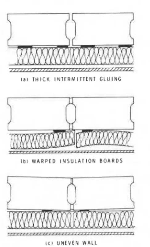
Most rigid board insulations provide a convection barrier, but poor joints can allow convective air flow around the boards. Although the insulation layer is fastened tightly to the wall, a thick intermittent glue layer and wall ir- regularities can create an air space beneath the insulation. Figure 1 il- lustrates this problem.
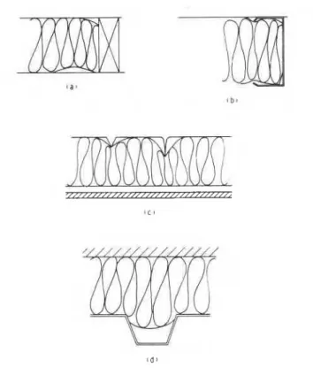
Fibrous insulation, unless paper-backed, does not provide a convection bar- rier. It must rely, therefore, on intimate contact with one side of the cavity to eliminate convective air flow. This may not always be achieved (Figs. 2a to
2d). In Fig. 3, which is taken from the work cited in Footnote 3, Line A
shows the conductance of an ideally installed insulation layer versus cold-side temperature. It shows the expected increase in conductance as the mean temperature of the specimen is raised. Line B is the conductance of an unfaced glass fiber insulation with an unobstructed air space on both sides. Besides the obvious increase in conductance due to convection, the slope of Line B in- dicates, as expected, an increase in convective air flow as the temperature
difference increases (or as cold-side temperature decreases). Line C shows
l a 1 T H I C K I N T E R M I T T E N T G L U I N G
I b l W A R P f D I N S U L A T I O N B O A R D S
I c ) U N E V E N W A L L
SCHUYLER AND SOLVASON ON INSULATION EFFECTIVENESS 545
FIG. 2-Examples of illrfitting wall insulation.
the conductance of a wall that was insulated according to current practice, namely a friction fit batt pushed into a stud space. The batt was wider than the stud space, and when it was compressed it wrinkled and air pockets were created on the cold-side surface. Line C can be compared with Line D, which is the same batt trimmed to fit the stud space exactly. Line E shows the results of measurements on a wall identical to that whose results are given by Line A, except that two 16-mm vertical grooves were formed in the insulation on the cold side of each stud space by wires strung the full height of the cavity. The conductance decreases until the weather-side temperature reaches ap-
proximately
-
12OC. At this point convective circulation starts, counter-acting any further decrease in conductance with decreasing weather-side temperature. It appears from this that convective air flow is inhibited until the temperature difference becomes large enough to overcome the flow path restriction.
As can be seen from Fig. 3, convective flow is sensitive to flow path size and length, and the temperature difference. A test is necessary to determine the R-value of wall specimens with convection paths.
546 THERMAL INSULATION. MATERIALS, AND SYSTEMS
-
1 I I r I I I1
A:
-
-
-
7-
W A R M T E M P E R A T U R E S I D E\\
Rr
-
-
TI !? 7 2 - F-
-
-
-
-
E -.---A- -.--A---.--.-
c - - m - - /O O-------
A- o - 0 2 - - - - B ----
-
----.---
-
D---_
I I I I I I I t C O L D - S I D E A I R T E M P E R A T U R E , T o . FFIG. 3-Over-all thermal conductance of panels m'f work cited in Footnote 3).
Test Procedure
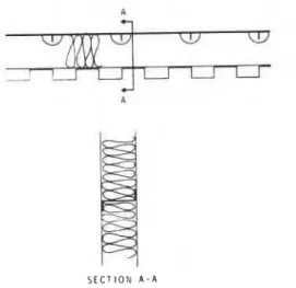
All resistance measurements quoted in this paper were made with the 2.4 by 2.4 m (8 by 8 ft) guarded hot box test facility of the Division of Building Research, National Research Council of Canada, as shown in Fig. 4.
Briefly, the facility consists of hot and cold chambers with a 3.048 m (10 ft) opening joining them. The opening is reduced to 2.44 m (8 ft) square by a polystyrene mask that constitutes the guard area. The test specimen is sealed into the opening, and the calorimeter is placed over the warm-side face of the specimen and sealed to the polystyrene mask.
All temperatures are measured by 30-gage Type T thermocouples. Power to the calorimeter is supplied by a d-e power supply to convective bar heaters inside. A baffle eliminates direct radiation from the heaters to the specimen. The calorimeter relies on natural convection and radiation to transfer heat to the specimen. A film coefficient of approximately 25 W/m2."C is produced
on the cold side by the cold-side conditioning fans.
To make a steady-state heat transmission measurement, the specimen is first allowed to settle to equilibrium at the prescribed temperature conditions
4 RFFRIGERATION
WEATHER SIDE CHAICIBER
ROOM SIDE CHAMBER CALORIMETER BOX TEST SPECIMEN 74 rnm ISOCYANURATE FOAM REFRIGERATION VERTICAL SECTION 152 rnm POLYURETHANE FOAM INSIDE A I R TEMPERATURE THERMOCOUPLES (Tal) rr BAFFLE TEMPERATURE 1HERMOCOUPLES (Tbl
o OUTSIDE A I R TEMPERATURL THERMOCOUPLES (Taol
548 THERMAL INSULATION, MATERIALS, AND SYSTEMS
on an automatic temperature control mode. When equilibrium is reached the input power is set manually to avoid control fluctuations during temperature measurements.
Results of Tests
Figure 5 illustrates schematically a common type of building construction
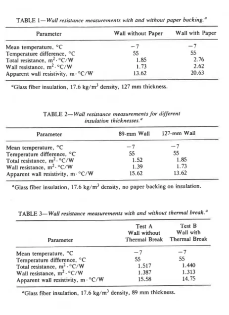
which can suffer from convective air flow if attention is not paid to the proper details. In this case the wall with 127-mm insulation was tested with and without paper backing glued to the glass fiber insulation. Table 1 shows the results of the two tests, indicating a 34 percent reduction in wall resistance when the paper is not present.
In another case, the same construction was used but with 89-mm insula- tion. Table 2 shows the comparison between the wall with an 89-mm thick insulation layer and a 127-mm layer. In this case, the resistance of the wall increased by only 24 percent when the insulation thickness was increased by 42 percent.
Degradation of the msistivity of the insulation layer by convective air flow
can also be aggravated by design details intended to increase the overalI resis-
tance of the wall system. Table 3 shows the results of two tests. In Test A the
steel spacer shown in Fig. 5 was used to separate the inner and outer panels
of the wall. In Test B all components remained the same, but a 6-rnm layer of
low-conductivity material was added to the flange of the spacer to reduce its thermal bridging effect. Comparison of the two wall resistances reveals that this "thermal break" actually reduced the resistance of the wall system be-
cause of the 6 mm increase in cavity thickness, which provided a less re-
strictive path for convective air flow.
S E C r l O N A - A
SCHUYLER AND SOLVASON ON INSULATION EFFECTIVENESS 549
TABLE 1-Wall resistance measurements with and without paper backing."
- -
-Parameter Wall without Paper Wall with Paper Mean temperature, "C
-
7 - 7Temperature difference, "C 55 55
Total resistance, m2. OC/W 1.85 2.76
Wall resistance, m2. OC/ W 1.73 2.62
Apparent wall resistivity, m. OC/W 13.62 20.63
"Glass fiber insulation, 17.6 kg/m3 density, 127 mm thickness.
TABLE 2- Wall resistance measurements for different
insulation t h i c k n e s s e ~ . ~
Parameter 89-mm Wall 127-mm Wall Mean temperature, OC -7 - 7 Temperature difference, "C 55 55
Total resistance, m2. OC/W 1.52 1.85 Wall resistance, m2. OC/W 1.39 1.73
Apparent wall resistivity, m. "C/W 15.62 13.62
'Glass fiber insulation, 17.6 kg/m3 density, no paper backing on insulation.
TABLE 3- Wall resistance measurements with and without thermal break." Test A Test B Wall without Wall with Parameter Thermal Break Thermal Break Mean temperature, "C - 7 -7
Temperature difference, "C 55 55
Total resistance, m2. OC/W 1.517 1.440
Wall resistance, m2. OC/W 1.387 1.313
Apparent wall resistivity, m . OC/W 15.58 14.75
'Glass fiber insulation, 17.6 kg/m3 density, 89 mm thickness.
Conclusions
Although thermal bridging is an important factor in the over-all resistance of a wall system, it is well known and proper attention is usually given to it at the design stage. Convective air flow within the wall cavity, however, does not re- ceive sufficient attention at the design stage. Assumptions about the actual position of the insulation are in error in many cases, as the examples have shown. Since the source of the problem is mostly protrusions into the insula- tion space and often inaccuracies in construction or product dimensions, this effect is virtually impossible to treat theoretically.
550
THERMAL INSULATION, MATERIALS, AND SYSTEMSFrom the results of tests conducted on frame walls, a few rules of good de- sign and detailing have become apparent:
1. The first and most important point is to provide an air barrier between the inner and outer surfaces of the insulation layer. In closed cell foam prod- ucts this can be achieved by providing airtight joints between boards. In porous insulations an air barrier such as a layer of paper should be applied to the insulation. This air barrier should be present even when the insulation is thought to be, although it seldom is, in intimate contact with one side of the cavity. The location of the air barrier is not important. It could be located on either face of the insulation layer or sandwiched within the insulation. The insulation would have a better chance to conform to the surface if the barrier were in the center.
2. To provide better contact with one side of the cavity, special attention should be paid to protrusions, hangers, etc. It should not be assumed that in- sulation will conform to the shape of such members. It is important, there- fore, to reduce the number, size, and complexity of such protrusions and, in many cases, to cut special insulation pieces to fit around them.
3. Dimensions and tolerances should provide some compression of a glass fiber insulation layer. It is also important that insulation be expanded to its reference thickness. Any insulation that does not meet its reference thickness should be rejected.
Convective air flow within the wall cavity is a problem with many of today's constructions, but need not be. Simple precautions and minor design changes can eliminate convective flow and assure proper performance for the customer and the manufacturer.
Acknowledgments
This paper is a contribution from the Division of Building Research, Na- tional Research Council of Canada, and is published with the approval of the Director of the Division.
T h i s publication irc being d i s t r i b u t e d by the Division of Building R e s e a r c h of t h e National R e s e a r c h Council of Canada. I t should n o t b e r e p r o d u c e d i n whole o r i n p a r t without p e r m i s s i o n of the o r i g i n a l p u b l i s h e r . T h e Di- v i s i o n would b e glad t o b e of a s s i s t a n c e i n obtaining s u c h p e r m i s s i o n .
P u b l i c a t i o n s of the Division m a y be obtained by m a i l - ing the a p p r o p r i a t e r e m i t t a n c e ( a Bank, E x p r e s s , o r P o s t Office Money O r d e r , o r a cheque, m a d e p a y a b l e t o the R e c e i v e r G e n e r a l of Canada, c r e d i t NRC) t o the N a t i o n a l R e s e a r c h Council of Canada, Ottawa. KIA OR6. S t a m p s a r e n o t a c c e p t a b l e .
A l i s t of a l l publications of the Division i s a v a i l a b l e and m a y b e obtained f r o m the P u b l i c a t i o n s Section, Division of Building R e s e a r c h , National R e s e a r c h Council of Canada, Ottawa. KIA OR6.