HAL Id: inria-00071820
https://hal.inria.fr/inria-00071820
Submitted on 23 May 2006
HAL is a multi-disciplinary open access
archive for the deposit and dissemination of
sci-entific research documents, whether they are
pub-lished or not. The documents may come from
teaching and research institutions in France or
abroad, or from public or private research centers.
L’archive ouverte pluridisciplinaire HAL, est
destinée au dépôt et à la diffusion de documents
scientifiques de niveau recherche, publiés ou non,
émanant des établissements d’enseignement et de
recherche français ou étrangers, des laboratoires
publics ou privés.
UML 2.0 Structure Diagram for Intensive Signal
Processing Application Specification
Cedric Dumoulin, Pierre Boulet, Jean-Luc Dekeyser, Philippe Marquet
To cite this version:
Cedric Dumoulin, Pierre Boulet, Jean-Luc Dekeyser, Philippe Marquet. UML 2.0 Structure Diagram
for Intensive Signal Processing Application Specification. [Research Report] RR-4766, INRIA. 2003.
�inria-00071820�
ISSN 0249-6399
ISRN INRIA/RR--4766--FR+ENG
a p p o r t
d e r e c h e r c h e
THÈME 1
INSTITUT NATIONAL DE RECHERCHE EN INFORMATIQUE ET EN AUTOMATIQUE
UML 2.0 Structure Diagram for Intensive Signal
Processing Application Specification
Cédric Dumoulin — Pierre Boulet — Jean-Luc Dekeyser — Philippe Marquet
N° 4766
Unité de recherche INRIA Futurs
Domaine de Voluceau, Rocquencourt, BP 105, 78153 Le Chesnay Cedex (France)
Téléphone : +33 1 39 63 55 11 — Télécopie : +33 1 39 63 53 30
UML 2.0 Structure Diagram for Intensive Signal
Processing Application Specification
C´
edric Dumoulin
∗, Pierre Boulet
∗, Jean-Luc Dekeyser
∗, Philippe Marquet
∗Th`eme 1 — R´eseaux et syst`emes Projet DaRT
Rapport de recherche n 4766 — March 11, 2003 — 15 pages
Abstract: Complexity in the digital systems integration rises from the heterogeneity of the components integrated in a chip. The simulation or code generation of such systems require to validate methodologies, platforms and technologies to support integration, verification and programming, of complex systems composed of heterogeneous virtual components.
Several formalisms are needed according to their applicability in order to propose a framework of formal specification. The unification of these formalisms leads to visually model intensive signal processing applications for embedded systems. A part of this methodology has come down from the Array-OL language. An application is represented by a graph of dependences between tasks and arrays. Thanks to the data-parallel paradigm, a task may iterate the same code on different patterns which tile its depending arrays.
The visual notation we propose uses a UML 2.0 standard proposal. This allows usage of existing UML 2.0 tools to model an application. A UML profile dedicated to Intensive Signal Processing with a strong semantics allows automatic code generation, automatic mapping on SoC architectures for early validation at the higher level of specification.
Key-words: UML 2.0, structure diagram, intensive signal processing, modeling, data-parallelism, data dependences
This work has been supported by the ITEA 99038 project, Sophocles.
∗Laboratoire d’Informatique Fondamentale de Lille, Universit´e des Sciences et Technologies de Lille, Cit´e
Utilisation du diagramme de structure d’UML 2.0 pour
la sp´
ecification d’applications de traitement de signal
intensif
R´esum´e : La complexit´e d’int´egration des syst`emes num´eriques vient de l’h´et´erog´en´e¨ıt´e des composants int´egr´es sur une puce. La simulation ou la g´en´eration de code pour de tels syst`emes n´ecessite la validation de m´ethodologies, de plate-formes et de technologies pour supporter l’int´egration, la v´erification et la programmation de syst`emes complexes compos´es de composants virtuels h´et´erog`enes.
En fonction de leur domaine d’application, plusieurs formalismes sont n´ecessaires pour proposer un cadre de sp´ecification formelle. L’unification de ces formalismes conduit `a la mod´elisation visuelle d’applications de traitement de signal intensif pour syst`emes embar-qu´es. Une partie de cette m´ethodologie vient du langage Array-OL. Une application y est repr´esent´ee comme un graphe de d´ependances entre des tˆaches et des tableaux. En utilisant le paradigme du parall´elisme de donn´ees, on peut d´ecrire la r´ep´etition d’une mˆeme tˆache sur diff´erent motifs pavant les tableaux avec lesquels elle est en relation de d´ependance.
La notation visuelle que nous proposons utilise une proposition de standard UML 2.0. Nous pouvons ainsi r´eutiliser les outils UML 2.0 pour mod´eliser une application. Nous proposons ici un profil UML d´edi´e au traitement de signal intensif avec une s´emantique forte permettant la g´en´eration de code automatique ou le placement sur des architectures de type SoC pour une validation au plus tˆot des sp´ecifications.
Mots-cl´es : UML 2.0, diagramme de structure, traitement de signal intensive, mod´elisa-tion, parall´elisme de donn´ees, d´ependances de donn´ees
Structure Diagram for ISP Application Specification 3
1
Introduction
In the next decade, the high performance software and hardware system development will play a crucial role in the field of telecommunications and multi-media applications. These systems will have to cover various problems, according to different points of view: from specification of the application to the realization of embedded hardware systems, via the implementation on high performance COTS (Components Off The Shelf ). These systems relate to intensive signal or image processing (numerical filtering, JPEG2000). They will re-quire programming environments for specification, simulation/verification, compilation and execution in order to reduce the time to market. The architecture of these systems will be basically heterogeneous. It will be based on the integration of various processing units (soft-ware and hard(soft-ware) devoted to specific functions like intensive processing, decision-making and monitoring. Unfortunately, the effort of programming and monitoring such digital sys-tems becomes increasingly complex. The evolution of the environments as often does not compete with the technology evolution.
The targeted embedded architectures have multiple processing units and very often some of them are parallel. Indeed, to exploit parallelism in architecture allows to reduce the clock frequency and by way of consequence its voltage supply. Consequently two fields of computing are brought to meet: systematic signal processing associated with intensive data processing where the processing of quantity of data must be ensured in respect of time constraints; and high performance computing in order to exploit parallelism as well as possible and to take into account intensive data flows.
In a SoC (System on Chip), the heterogeneity of the virtual components (or Intellectual Properties, IPs) and the scarcity of a development environment for each one oblige to have recourse to some IP assembler. The user goes to and fro between specification of the appli-cation and optimization of the code produced on a given machine, often using tools of low level where differentiation between these two tasks is not clearly established.
Our objectives are the same ones as those of the traditional programming: to model, to unify and to re-use! The difference comes from the application domain itself. The restriction to a domain makes these objectives reachable by the proposal of a specific framework for the development of data-parallel applications dedicated to signal processing. We propose a model based on single assignment and the explicit expression of dependences which they are temporal or spatial. To ensure respect of the standards used in the industrial world, our proposals are integrated in the UML (Unified Modeling Language) formalism [8].
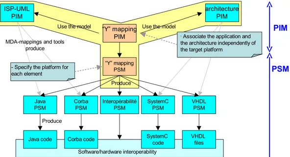
Needs of independence between application and architecture result from the diversity of our targets. Currently, due to the lack of high level specification tools, the developers mix the application itself with its execution on a particular machine. The consequence of this type of development is the lack of reusability, dynamicity and thus a heavy and often repetitive work. The observation of implemented techniques in industrial projects leads us to propose a separation of application specification, architecture specification and mapping specification of an application on a particular architecture. This specification methodology in a “Y” style [5] authorizes by construction to re-use as well the application as the architecture.
4 Dumoulin, Boulet, Dekeyser & Marquet
The “Y” Model The “Y” model is based on three models in a single environment allowing a visual specification of ISP (intensive signal processing) applications, target architectures and deployment of applications on architectures. This particular model allows to differentiate the specification, the support of execution and the execution as such.
The separation of the three models opens the way of the reusability. The same architec-ture or application will be able to appear in several projects; in particular one must be able to re-use an application on a new architecture, to develop a new application or to transform an application on an existing architecture. Of course the mapping remains related on the application and architecture, even if it is independent of the execution/simulation platform (SystemC, etc).
From this analysis we can extract a certain number of criteria common to the three models:
To use the same formalism: a user must be able to go easily from a specification to another without having to learn new concepts. It comes from the expression of the dependences: spatial and temporal for the applications, data flow on time for the hardware components.
To use the same notation: here we retain the UML “visual language”, to which we add appropriate profiles: one dedicated to ISP, one to the architecture, and one for the de-ployment. We plan thereafter to provide a language derived from UML and dedicated to ISP. This language will be expressed using the MOF [7].
To use the same internal representation: the visual and exploitation tools of the mod-els use internal representations (memory or persistent representations). We propose a common representation to all the tools we develop, as well as basic interfaces/libraries which allow its handling.
To use the same external tools: the tools used can be the same ones for the various specifications, so that the users can go easily from one specification to another. To ensure an automatic exploitation: various methodologies will allow automatically
to obtain models of mapped applications usable by various tools such as code genera-tors, simulators...
At this level, the model remains independent of the execution or simulation platform. It is then, in respect of MDA [1] philosophy (figure 1), that projection on execution models such as SystemC, VHDL, CORBA or IP simulators will produce a heterogeneous specific representation to the target platforms. All these codes will have to be inter-operable in order to ensure the communications between the IPs.
Only the application specification model will be described in this paper. From the Array-OL language we will show how it is possible to reach a formal specification model in a UML framework. Thanks to the UML 2.0 proposal, structure diagrams will be used to describe several levels of data dependences.
Structure Diagram for ISP Application Specification 5
Figure 1: Specification with a MDA philosophy
2
From the Array-OL Language. . .
Array-OL (Array Oriented Language [4, 2]) was developed by Thomson Marconi Sonar in order to fulfill the needs for specification, standardization and efficiency of multidimensional signal processing. Array-OL relies on a graphical formalism in which the signal processing appears as a graph of tasks. Each task is performed on multidimensional arrays.
Array-OL proposes a two level approach. The first level is a global level (figure 2) and defines task coordination by the way of dependences between tasks and arrays. A second level, which is local (figure 3), details the elementary actions which are carried out by a task on array elements.
Figure 2: Array-OL global model: a directed acyclic graph of tasks and arrays
6 Dumoulin, Boulet, Dekeyser & Marquet
Figure 3: Array-OL local model: parallel instances of an elementary task
Global Model: This looks like the well-known static data-flow model. The application is represented as a graph where each node represents a task and the edges define dependences between tasks. Each edge carries an array. Nevertheless, in the static data-flow model, the graph edges carry a continuous token flow of all the tasks running in parallel. In the Array-OL model, an edge carries a single array (which may be of infinite size) and each task is triggered only once. A graph node (task) execution produces its output arrays from its input arrays. The task specification and the details of the array element usage are hidden at this specification level.
The array defines a data structure for signal processing:
Signal processing applications are organized around a regular and potentially infinite stream of data. Array-OL captures this stream in arrays with one possible infinite length dimension.
Some spatial dimensions of arrays used in signal processing correspond to sensors. Such sensors may be organized in a circle. Consequently, Array-OL array dimensions wrap around to form a toroid.
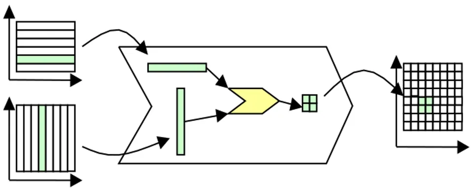
Local Model: It details the task specification. It defines the access to the data in the arrays and the computations to be done on those data. The whole task execution is divided into small identical computational units called Elementary Transformations (ET). An ET operates on subsets of the arrays called patterns. Output patterns (patterns in the output arrays) are produced by applying the ET on the patterns of the input arrays. So, a task always consists of an iterator constructor which iterations are independent.
Fitting and Paving
– Patterns are multidimensional arrays. Equidistant elements in a pattern are also equidistant in the array. A pattern may be defined by an origin in the array and
Structure Diagram for ISP Application Specification 7
a set of vectors (fitting vectors; one vector being associated to each dimension of the pattern).
– Two equidistant output patterns are produced by two equidistant input patterns. The array paving with patterns is given by a first pattern in each array and a set of paving vectors.
ET Library or Hierarchical Definition
– For each paving iteration, the input patterns are extracted from the input arrays and an ET is applied on these patterns to produce the outputs. These patterns are then stored in the output arrays.
– A library of predefined ETs is available on different computer architectures to process generic data parallel tasks.
– A hierarchical extension of Array-OL allows the programmer to define his own ET in Array-OL. Input/output patterns of the first level are considered as arrays on the sub-level of the hierarchy. A new Array-OL global level defines tasks that manipulate these arrays. This hierarchical construction may be applied as many times as necessary.
Signal processing dedicated to detection systems refers to multidimensional arrays. As in digital sound processing, a first dimension allows sampling the signal in chronological order. A second dimension generally represents the different sensors; the temporal sampling is applied on each of them. During the signal processing, other dimensions may appear. For example during the FFT implementation a new dimension represents the frequency. The temporal reference is modified and matches the sampling of the different FFT execution ages.
Despite its ability to express signal processing applications, Array-OL lacks a formal visual modeling tool and associated compilers. This is a gap that we wish to fill.
3
. . . To UML
The choice of UML [8] and especially the UML 2.0 proposal from U2 partners [11] as a common language of modeling was essential because of its advantages:
UML is a recognized standard and more and more used, especially in industrial projects.
It offers extension mechanisms (stereotypes, tagged values, profiles) enabling us to bring our own elements without modifying UML itself.
It does not impose the use of a particular methodology. We can validate our own methodology, in particular our “Y” model.
It is visual as well as textual.
8 Dumoulin, Boulet, Dekeyser & Marquet
Various visual tools already exist around the UML standard (Rational Rose [13], Ob-jecteering [12], Tau G2 [16], etc).
UML is modeled by a metamodel specified itself by the MOF [7]. This enables us to provide our clean metamodel which will be initially an extension of UML. Later, by reduction of these specifications our metamodel will provide only what is really necessary to the specification of ISP applications.
The exchange of models between the tools is (more or less) ensured by standard XMI/XML [10]. The tools we will develop will profit from an internal representa-tion based on the metamodel of our ISP UML language (expressed using the MOF). Persistence, as well as the exchange with the other tools, is done using XMI/XML. UML was originally designed in order to model the artifacts of a system with a large software part. This includes the specification of applications, architectures and the deployment of applications on architectures. It is thus theoretically possible to specify an ISP application with UML. However, no methodology allowing an automatic exploitation of the model exists for ISP applications. This is the gap we propose to fill. Moreover, the concepts of UML allowing the visual specification of an architecture and the deployment of the application based on this architecture are recognized as being the “poor relations” of UML. Here again, we will propose a methodology using UML to allow the specification of complex architectures used in ISP and the application deployment on these architectures.
Other projects proposing the modeling of real time or embedded applications also made the choice of the UML(-like) language. Thus, telecommunications are proposing a new ver-sion of SDL (Syntax Description Language), SDL-2000 [15] UML-oriented. The theoretical model of SDL is based on finite state machine, parallel agents (kind of classes) communicate together by signals. SDL does not allow the specification of architectures or the deployment. The UML community proposes extensions of UML (UML-RT, RT-UML [14, 9]) dedicated to the modeling of real time applications. These proposals are also oriented towards ap-plications communicating by signals. They allow code generation but do not integrate the architecture specification. The “Embedded UML” proposal [6] develops a synthesis of the existing models by retaining only the attractive points. It proposes to separate the three specifications: application, architecture and deployment. The link with the execution plat-forms is done during the deployment specification. Again the communication between the “blocks” is done by signals. Our approach is different from the preceding projects: we want to model applications by the expression of the dependences, rather than by signal exchanges or message passing. Moreover, we want clearly to separate the different specifications and thus to allow the re-use of applications and architectures
4
ISP UML: Application Specification
Our objective relates to the specification of algorithms on a high level of abstraction. We deduced the following constraints from the observation of various models of specification used by industrial partners.
Structure Diagram for ISP Application Specification 9
Single assignment: The data are mainly arrays which are produced by an elementary processing task and consumed without modification by other elementary tasks. This single assignment of arrays facilitates the visual specification of an application. Unification of temporal and spatial dimensions: Dimensions of arrays are mainly
as-sociated with concepts suitable for the application (hydrophones, sensors, energy...). One among them can be associated with time. It allows the identification of the var-ious values of these same concepts during the life of the application. This dimension size becomes infinite for an embedded application.
Expression of the temporal and spatial dependences: The dependences represents the only bond which links the various objects handled by the program. They express the dependences between the elements of the objects (arrays) in input/output of each ele-mentary task. Only true dependences are explicited, either at the array level or at the array elements level. It covers as well space dimensions as temporal ones. It allows di-rect implementation of the compilation techniques. It guarantees implicit parallelism by the expression of partial order based on the dependences between objects. We identify two types of dependences
1. “Array” dependences: Global model of Array-OL, process networks, Yapi [3]. 2. “Iterative” dependences: local model of Array-OL, forall of the data-parallel
lan-guages.
5
ISP UML Framework
The main concept of our proposal is the “intensive signal processing component” (ISP-component. An application is modeled by assembling “ISP-components”, connected with “connections”, through their “ports”. ISP-components represent Array-OL global model tasks. Connections between ports materialize dependences. Some object oriented (OO) concepts enable to reuse of ISP-components.
5.1
ISP-Components
The ISP-component is the main modeling element. It is composed of an interface and it embeds a behavior. The interface describes ports that are used as potential endpoints for connections. The interface is the only way for a component to interact with the outside world. Its implementation is encapsulated and is completely hidden from outside world. This allows to change an implementation independently of any other components, as long as the new implementation respects the behavior and the interface.
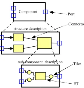
The behavior is described in what we call the component structure. It is a graph of (sub-)components connected by their ports. This structure allows a hierarchical description of components (figure 4). An application is itself a component made of sub-components, themselves eventually described with other components, etc.
10 Dumoulin, Boulet, Dekeyser & Marquet
Figure 4: Compound component structure
As an alternative, the behavior can be specified by the name of a function from an existing library, or written in some language. In these cases the component corresponds to an Elementary Task of Array-OL.
5.2
Ports
The ports represent proxies for data handled by components. They are used as endpoints of connections. They are directed: “In”-ports require some inputs, and “out”-ports provide some outputs. The interconnections of components via their ports form a directed acyclic graph representing the dependence graph.
A port also specifies the type of the data it carries. This type is defined by an interface in the OO sense. The framework does not impose any type. It is possible to define user types, and, thanks to the OO concept, to create a hierarchy of types. In the ISP model, ports are defined to carry arrays using a given ancestor array type.
5.3
Connections
The connections are used to connect ports of components. A connection is directed and represents the dependence between two components. To ensure model consistency only ports with compatible types can be connected. Compatible means that the types are assignment compatible in the OO sense.
Structure Diagram for ISP Application Specification 11
5.4
Data-parallelism Expression
In ISP UML, we introduce “data-parallel components” to perform parallel signal process-ing (similar to the “local model” of Array-OL). A nested sub-component represents the task applied in parallel over data (check the sub-component in figure 4). The ports of the data-parallel component and those of the nested component are indirectly connected: an intermediate tiler (a special component) represents the “iterative dependences”. The tilers describe how paving and fitting are applied to gather/scatter the corresponding patterns. The sub-component is executed once for each resulting set of patterns. The model says nothing about the execution model (sequential, parallel, pipe-line).
5.5
OO Concepts
There is a clear separation between an ISP-component definition and its usage. Thus we have a class/instance relationship similar to the one found in OO languages. The definition of an ISP-component (a class) is made of a component interface and a component behavior. ISP-component instances are found in component structures that describe behavior. This separation between a definition and its instances allows to build libraries of reusable com-ponents. A component can be defined by inheritance from another one, like inheritance of classes. This allows to reuse of existing ISP-components. The same OO concepts can be applied to ports, providing libraries of reusable ports and extensions of the existing ones.
A component with no behavior can be considered as an “interface” in the meaning of OO terminology. Interfaces are useful to define families of interchangeable components.
6
UML 2.0 Profile
The translation of our framework to UML profile uses the stereotype and tagged value extension mechanism. ISP-components and ports are classes with appropriate stereotype, while attributes like port direction are specified with tagged values.
The description of a component behavior (the component structure) is modeled with the new UML 2.0 diagram, the “structure diagram”.
The modeling can be done with any UML tools, but it is preferable to chose one able to export and import model in the standard XML/XMI way. This allows our automatic tools to exploit the model.
6.1
Structure Diagrams
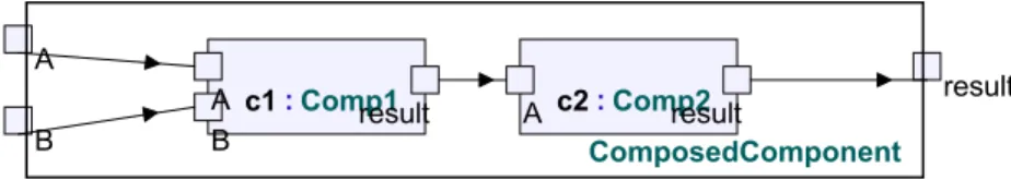
In the proposed structure diagram (figure 5), the current component is visualized as a surrounding box containing sub-components which are visualized as a nested box. The ports are drawn on the border of the component. The connections between components are materialized by connectors between the corresponding ports. Such a connection can be indirected via a single tiler in the case of data-parallel components.
12 Dumoulin, Boulet, Dekeyser & Marquet
A
c1:Comp1result c2:Com result
A A resultp2
B B
ComposedComponent
Figure 5: Structure diagram of a compound component (from TAU G2)
The UML 2.0 tools provide edition and visualization of tagged values and attributes and interactive navigation between ISP-components.
The UML 2.0 structure diagram is largely inspired from its counterpart in UML-RT. The difference is, once again, that connectors represent dependence expressions instead of signal exchanges. Its usage should be familiar to the users of the UML-RT formalism.
6.2
Ports
Our port concept is mapped onto the port modeling element of UML 2.0. A concrete port type is defined in a class stereotyped «portType». It is possible to refine its description by using the OO extension mechanism. In ISP UML, all port types inherit from a well-known class called AolArray which defines array basic attributes: element type, number of dimensions and size of each dimension.
6.3
ISP-components
The ISP-component concept is mapped to a class stereotyped «IspComponent». The com-ponent interface is described by a set of attributes stereotyped «port».
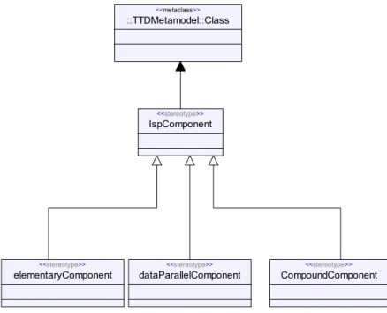
ISP-components are derived in three flavors 7:
Compound components stereotyped «compoundComponent»; their structure are com-posed only from ISP-components and connectors. This corresponds to the global model of Array-OL. See figure 5.
Data-parallel components stereotyped «dataParallelComponent», composed of a unique nested ISP-component and one tiler component on each connection. This corresponds to the local model of Array-OL. See figure 6.
Elementary components stereotyped «elementaryComponent», which have no struc-ture but directly refer to an external implementation.
Structure Diagram for ISP Application Specification 13 input1 input2 'output' task:ElementaryFilter input1 input2 'output' qd1:aol::AolTiler <<aolTiler>> array pattern qd2:aol::AolTiler <<aolTiler>> array pattern qd3:aol::AolTiler <<aolTiler>> array pattern
Figure 6: A data-parallel component
elementaryComponent <<stereotype>> ::TTDMetamodel::Class <<metaclass>> CompoundComponent <<stereotype>> IspComponent <<stereotype>> dataParallelComponent <<stereotype>>
Figure 7: The ISP-component stereotypes hierarchy
6.4
Tiler Components
The tiler component concept is mapped to the part (structured class modeling element introduced in UML 2.0) stereotyped «tiler». The «aolTiler» stereotype is derived from the previous one and adds the tagged values to specify the origin, fitting and paving values.
14 Dumoulin, Boulet, Dekeyser & Marquet
7
Conclusion and Perspectives
We have presented a methodology to visually model intensive signal processing applica-tions using the UML 2.0 proposal visual notation and the Array-OL formalism based on dependence expressions. This methodology allows the development of reusable “pieces of software” aimed to intensive signal processing embedded applications. Reuse is one of the key to reduce development time and to achieve the “time to market” constraint.
The resulting models can be exploited automatically by tools like visualization, simula-tion, transformasimula-tion, code generation. This is possible because we restrict our domain to intensive signal processing applications and because we strictly specify the rules to model such applications in our ISP UML profile.
In the future, heterogeneous embedded systems will be taken into account by the adjunc-tion of the architecture and deployment specificaadjunc-tion in what we call a “Y” model (separaadjunc-tion of application, architecture and deployment description).
The architecture and deployment specifications will follow the same formalism used for the application description, providing a consistent set of high level specification tools for embedded system design.
We also consider integration of new elements to our “visual language”. As example, we will develop a new kind of dependence allowing modeling of irregular applications with non systematic processing.
ISP UML together with architecture and deployment specifications stay independent from the simulation and execution platforms. A model to model translation (mapping rules of MDA) will allows to target different platforms such as SystemC and CORBA for simulation and specific assembly languages for IPs.
References
[1] OMG Architecture Board. Model driven architecture (MDA). Technical report, OMG, 2001. ormsc/2001-07-01.
[2] Pierre Boulet, Jean-Luc Dekeyser, Jean-Luc Levaire, Philippe Marquet, Julien Soula, and Alain Demeure. Visual data-parallel programming for signal processing applica-tions. In 9th Euromicro Workshop on Parallel and Distributed Processing, PDP 2001, pages 105–112, Mantova, Italy, February 2001.
[3] E. A. de Kock, G. Essink, W. J. M. Smits, P. van der Wolf, J.-Y. Brunel, W. M. Krui-jtzer, P. Lieverse, and K. A. Vissers. YAPI: Application modeling for signal processing systems. In 37th Design Automation Conference, Los Angeles, CA, June 2000. ACM Press.
[4] Alain Demeure and Yannick Del Gallo. An array approach for signal processing design. In Sophia-Antipolis conference on Micro-Electronics (SAME), France, October 1998.
Structure Diagram for ISP Application Specification 15
[5] D. D. Gajski and R. Kuhn. Guest editor introduction: New VLSI-tools. IEEE Com-puter, 16(12):11–14, December 1983.
[6] Grant Martin, Luciano Lavagno, and Jean-Louis Guerin. Embedded UML: a merger of real-time uml and co-design. http://www.gigascale.org/pubs/101.html, March 2001.
[7] Object Management Group, Inc. MOF meta object facility, specification, version 1.3. http://www.omg.org/cgi-bin/doc?formal/00-04-03, January 2000.
[8] Object Management Group, Inc., editor. Unified Modeling Language (UML), Ver-sion 1.4. http://www.omg.org/technology/documents/formal/uml.htm, September 2001.
[9] Object Management Group, Inc., editor. (UML) Profile for Schedulability, Performance, and Time Specification. http://www.omg.org/cgi-bin/doc?ptc/ 2002-03-02/, May 2002.
[10] Object Management Group, Inc., editor. XML Metadata Interchange (XMI), Version 1.2. http://www.omg.org/technology/documents/formal/xmi.htm, January 2002. [11] Object Management Group, Inc., editor. U2 Partners’ (UML 2.0): Superstructure,
2nd revised submission. {http://cgi.omg.org/cgi-bin/doc?ad/03-01-02/}, Jan-uary 2003.
[12] Objecteering Software. Objecteering version 5.2. http://www.objecteering.com/, 2002.
[13] Rational. Rational Rose v2001: Visual modeling, UML, object-oriented, component-based development with Rational Rose. http://www.rational.com/products/rose/ index.jsp, 2001.
[14] B. Selic and J. Rumbaugh. Using UML for modeling complex real-time systems. White paper, Rational Rose, 1998.
[15] Telecommunication Standardization Sector of Itu. Specification and description lan-guage (SDL). http://www.itu.int/ITU-T/studygroups/com10/lanlan-guages/Z.100_ 1199.pdf, 1999.
[16] Telelogic. Tau generation 2. http://www.taug2.com/, 2002.
Unité de recherche INRIA Futurs
Domaine de Voluceau - Rocquencourt - BP 105 - 78153 Le Chesnay Cedex (France)
Unité de recherche INRIA Lorraine : LORIA, Technopôle de Nancy-Brabois - Campus scientifique 615, rue du Jardin Botanique - BP 101 - 54602 Villers-lès-Nancy Cedex (France)
Unité de recherche INRIA Rennes : IRISA, Campus universitaire de Beaulieu - 35042 Rennes Cedex (France) Unité de recherche INRIA Rhône-Alpes : 655, avenue de l’Europe - 38330 Montbonnot-St-Martin (France) Unité de recherche INRIA Rocquencourt : Domaine de Voluceau - Rocquencourt - BP 105 - 78153 Le Chesnay Cedex (France)
Unité de recherche INRIA Sophia Antipolis : 2004, route des Lucioles - BP 93 - 06902 Sophia Antipolis Cedex (France)
Éditeur
INRIA - Domaine de Voluceau - Rocquencourt, BP 105 - 78153 Le Chesnay Cedex (France)
http://www.inria.fr ISSN 0249-6399