HAL Id: in2p3-00012510
http://hal.in2p3.fr/in2p3-00012510
Submitted on 7 Feb 2003
HAL is a multi-disciplinary open access
archive for the deposit and dissemination of
sci-entific research documents, whether they are
pub-lished or not. The documents may come from
teaching and research institutions in France or
abroad, or from public or private research centers.
L’archive ouverte pluridisciplinaire HAL, est
destinée au dépôt et à la diffusion de documents
scientifiques de niveau recherche, publiés ou non,
émanant des établissements d’enseignement et de
recherche français ou étrangers, des laboratoires
publics ou privés.
LINAG phase I
W. Mittig
To cite this version:
LINAG Phase I
A Technical Report
Version : 1.3
Chapter I : Introduction
1
Chapter II : Production of RIBs by fragmentation and ISOL
3
II.1) GENERAL REMARKS 3
II.2) PRODUCTION OF ACCELERATED ISOL-RIBs FROM FISSION AND COMPARISON WITH PHOTO-INDUCED
FISSION. 4
Chapter III : Hight intensity multi-charge ion sources for LINAG I
9
III.1) CONSTRAINTS 9
III.2) MULTI-CHARGED ION SOURCES. 9
III.2.1) Current state of the art 9
III.2.2) Beam characteristics 10
III.2.3) Cost estimate and time-scale 10
Chapter IV : The linear accelerator
11
IV.1.) GENERAL LAYOUT OF THE LINEAR ACCELERATOR 11
IV.2) SOURCE AND LOW ENERGY BEAM TRANSPORT LINE 11
IV.3) THE RFQ INJECTOR. 12
IV.4) THE SUPERCONDUCTING LINEAR ACCELERATOR 14
IV.5) LAYOUT OF THE DRIVER 20
IV.6) REVIEW OF THE DRIVER COST EVALUATION. 21
Chapter V : The Target and Ion Source
23
V.1) THE PRODUCTION OF FISSION FRAGMENTS 23
V.1.1) The rotating target/converter 24
V.1.2) The target and ion source production system 25
V.1.3) Production rates 27
V.2) RADIOPROTECTION AND TARGET HANDLING 29
Chapter VI : Security and Radioprotection
39
VI.1.1) Ion Source 40
VI.1.2) The RFQ 40
VI.1.3) The Linear Accelerator 40
VI.2.1) Ion source 41
VI.2.2) RFQ 41
VI.2.3) LINAC 42
VI.2.4) The High Energy Beam Transport Line (HEBT) 42
VI.2.5) Beam accidents 42
VI.2.6) Shielding for the target/ion-source 43
VI.2.7) The authorisation procedures 43
Chapter VII : Siting, postacceleration and coupling to experimental areas.
45
VII.1) POST ACCELERATION OPTIONS 47
VII.1.1) Post acceleration in using the CIME cyclotron 47
VII.1.2) Re injection of the CIME beams into CSS2 47
VII.1.3) Post acceleration with C0+CSS1+CSS2 49
Chapter VIII : Possible links between LINAG and EURISOL
54
VIII.1) BACKGROUND TO EURISOL 54
VIII.2) SYNERGIES 54
Chapter IX : Summary of costs and general schedule
56
LINAG phase I
Chapter I : Introduction
I
n a first report [ref. 1] the possibility of a high intensity accelerator at GANIL, producing secondary beams of unprecedented intensity, was considered. As was outlined in that report, LINAG I, a low energy high intensity linear accelerator constituting a first phase of this more general project, could produce secondary beams either from fission products, or from fusion-evaporation or deep inelastic reac-tions. The Scientific Council and Directors of GANIL rec-ommended a more detailed technical study of LINAG I as a possible option for the SPIRAL II project [ref. 2], to be com-pared to the photofission option. This is the objective of the present report. We will first remind readers of the general context.The systematic and very successful use of high ener-gy fragmentation at GANIL, (the first operational high inten-sity heavy ion accelerator in the 50-100 MeV/nucleon domain) for exploring the structure of nuclei far from stabil-ity, triggered the question of how to proceed even further in this domain. The study of nuclei far from stability has become one of the major activities at GANIL, and is one of its domains of excellence. In near future, the possibility of producing and accelerating radioactive beams by the ISOL method will become available. For this reason the Directors and the Scientific Council of GANIL decided about four years ago to initiate a study of long range perspectives. The results of the working groups can be found in the minutes of the Scientific Council, and the physics case will be published soon.
A pre-project study named SPIRAL II [ref. 2, 3], was undertaken in order to add medium-mass nuclei to the ones available with SPIRAL. In this project, fission induced by light particles (e, p, d, etc... ) is proposed to produce the radioactive ions, with an aim of 1013fissions/s at least, with
and without a converter (an intermediate target for producing high fluxes of neutrons).
It is clear that the final intensities of RIBs will deter-mine the domains of the nuclear chart that will be accessible to experiments. This implies a need for high intensity primary beams and versatile production techniques. Following these scientific needs, GSI is considering an upgrade of its facility, to provide 1012ions/s from p to U at 1.5 GeV. The USA
proj-ect RIA is planning to use several hundreds of kW of primary beams—from protons to U—at about 400 MeV/nucleon. The ISAC facility at TRIUMF uses already 20 µA (1.2 x 10¹⁴p/s)
of protons at 500 MeV for spallation production of ISOL beams, and will be able to use 5 times higher intensities in the future. The UK has proposed a high intensity proton acceler-ator for fission and fusion-evaporation reactions. RIKEN in Japan is starting an energy and intensity upgrade. In Europe, a study group is considering various solutions for EURISOL, an eventual European ISOL facility for provision of intense radioactive ion beams. The LNL laboratory in Legnaro, Italy, is considering a high intensity low energy proton driver, called SPES. Links to these projects can be found in [ref. 4]. In this context of fast evolution on the European and international level we consider here the possibility of an intensity upgrade of GANIL in its domain of excellence, i.e. beams in the energy domain of about 100 MeV/nucleon for low- to medium-mass nuclei (A<100). We have evaluated the possibility of producing beams of several hundreds of kilo-watts, i.e. of the order of 1 mA, corresponding to 6 x 10¹⁵
par-ticles/s for light particles and 3 x 10¹⁴/s for heavier particles.
The present accelerator configuration consisting of three cyclotrons in a cascade will not be capable of furnishing such high intensities. At present, the highest beam powers reached are in the 2–6 kW domain, or 2 x 10¹³particles/s. It is not
real-istic to expect a very significant increase with respect to such values. With present technologies, only linear accelerators are capable of producing such high intensities. Moreover, recent progress in high intensity ion sources for high charge states is another important feature to be taken into account. For this reason, we are considering the possibility of the con-struction of a very high intensity linear accelerator at GANIL in this energy and mass domain. Such a possibility would be complementary to the RIKEN, GSI and RIA projects, opti-mised in a different mass-energy domain.
The project, as outlined below, can be constructed in various phases, starting at low energy. It would cover a broad range of possibilities of primary and secondary beams. Very high intensity primary beams would be available from below the Coulomb barrier to 100 MeV/n from deuterons to mass 100 nuclei. Even intense heavy beams like U could be accel-erated to somewhat lower energy. These beams could be used for the production of intense secondary beams by all reaction mechanisms (fusion, fission, fragmentation, spallation, etc.) and technical methods (recoil spectrometers, ISOL, IGISOL, etc.). Thus, the most advantageous method for a given prob-lem of physics could be chosen. In the first phase, this
corre-sponds to an acceleration potential of about 40 MV, with fis-sion induced by neutrons from a converter, or by direct beams such as d, 3He or 4He, and fusion-evaporation reactions would
be available.
The present work was done, as stated in the title, as an internal consideration of the possibilities of producing these high intensity beams at GANIL. It is clear that any proj-ect has to be integrated in a European and international con-text. In particular, we need to be aware of the EURISOL
proj-ect, at present still a site-independent study, and the possibil-ities for LINAG—or some sections of it—to form part of this future project. For example, the EURISOL post-accelerator, planned for accelerating very heavy ions to some 100 MeV/u, has essentially the same specifications as that proposed here for the primary LINAG driver.
References
1) http//www.ganil.fr/research/sp/reports/files/linag.pdf
2) M.G. Saint Laurent et al. , SPIRAL phase II European RTD report, GANIL R 01-03 2001. 3) http//www.ganil.fr/spiral2/spiral_phaseII.pdf
LINAG phase I
Chapter II : Production of RIBs by fragmentation and ISOL
II.1) GENERAL REMARKS
T
o achieve high intensities of RIBs, whilst reaching very far from stability regions, it will be of fundamen-tal importance to take advantage of various strategies in the production scheme. Therefore, modern “next-genera-tion” exotic ion beam facilities should consider all available techniques for the production of radioactive elements. Only a multi-beam heavy ion driver offers the possibility of adapting the best production method to the requested radioactive ion beam specifications. This is the main asset of the present GANIL laboratory, as this unique facility offers both thin-tar-get (in-flight) and thick-tarthin-tar-get (ISOL) methods.The facility considered in this document represents an intensity upgrade of the present GANIL laboratory, with the same characteristics of the production systems and a fac-tor of 100–500 higher primary beam intensity. This new facil-ity could provide an upgrade of the RIB final intensfacil-ity of the same order of magnitude, i.e. 100–500 higher.
If one considers an improved separator with characteristics similar to the new A1900, recently commissioned at MSU [ref. 1], the final intensity of in-flight RIBs can be increased of another factor 10 to 100 as compared to present devices at GANIL such as SISSI and LISE.
All possible production schemes potentially avail-able in such a facility are shown in figure II.1, with the two main branches of thin-target (in-flight) and thick-target (ISOL) methods. Primary beams are shown in green, ion beams in red and neutral particles in black.
In the in-flight method, the primary beam hits a thin target so that the reaction products escape from the target with energies close to that of the beam. Such fragmentation reactions are favourable when high-energy heavy ions hit a suitable target. The fragments are directed forward in a nar-row cone at considerable energy, but with a large momentum spread. As much as possible of the beam is accepted into a separator and a particular isotope selected. The energy from the reaction is usually high enough for many nuclear physics experiments at intermediate energy (see the GANIL reports since 1987).
In the ISOL method—presently in use at SPIRAL—the pri-mary beam hits a thick target : the reaction products are stopped in the target material and diffuse out to the surface. Then they pass through the target voids (effuse) and
eventu-HIGH ENERGY ION BEAM Thin Target Combined Neutron and Thick Target To Experiment or Post-Accelerator Catcher/ Ion guide Neutron Target Helium Jet Gas
Catcher PARTICLESSTOPPED
Isotope Separator Thick Target Ion Source Solid Catcher
Thin Target Method (In-Flight) Thick target Method (ISOL)
Fragment Separator
Charge Particle Accelerator: Protons, Deuterons and
Heavy Ions Charged Particle Accelerator:
Heavy Ions
ally reach the ioniser and are extracted as an ion beam. The beam is mass-analysed and the selected isotope transmitted to the experiment or to a post-accelerator. A variation of the ISOL method is to use protons or deuterons into a neutron-producting “converter” target, from which the neutrons then interact with a thick production target. The converter and the production target can also be one and the same target.
The thin-target and thick-target methods can be combined ; the particles from the thin fragmentation target are stopped in a thick target and then pass into the rest of the ISOL system. Alternatively the particles can be stopped in a gas catcher and passed into the ion source via a helium gas jet. Another variation on this is to stop the energetic particles in a gas and then have a helium gas ion-guide system or IGISOL (Ion-Guide Isotope Separator On-Line). The parti-cles emerge from the IGISOL as singly charged ions, avoid-ing the need for a separate ioniser.
With the use of a thin target technique, all the parti-cles are released instantaneously, whereas in the thick-target technique, where all the particles are stopped, there may be
Figure II-1 : All potential RIB production methods with a heavy ion driver [ref. 2]. GANIL has already developed and routinely uses most of the branches shown.
considerable delay in the release. This is due to the slow dif-fusion out of the target and efdif-fusion through the target void to the ioniser. In addition, many particles stick physically or chemically to the surfaces. If the effusion time is longer than the lifetime of the radioactive particles, they will decay before reaching the ioniser.
The combination of these two techniques allows one to have a complementary and complete range of radioactive species available for experiments in a large energy range. The obvious extra advantage of this concept is that the GANIL team has already the know-how for the various production schemes proposed in this document. It is a straightforward upgrade of the present facility.
For a more detailed comparison between production methods and yields see [ref. 3].
II.2) PRODUCTION OF ACCELERATED ISOL-RIBs FROM FISSION AND COMPARISON WITH PHOTO-INDUCED FISSION.
Fission yields from 40 MeV deuterons with con-verter as compared to the fission yield from elec-trons
Deuterons of 40 MeV will produce in the converter neutrons centered at around 14 MeV that will induce fission of the compound nucleus
239U at an excitation energy of about 19 MeV.
Electrons will induce fission centered at the giant dipole resonance (GDR) in 238U at about 15 MeV
of excitation energy. Thermal neutrons on 235U
induce fission at an excitation energy equal to the binding energy of the neutron, 6.54 MeV. Fast neutrons from fission are centered around 2 MeV. We will present the results of two model calcula-tions for the different reaccalcula-tions. The first one is from [ref. 4]. The fission yields for neutron-induced fission were obtained from http://iso-topes.lbl.gov/fission.html, and are commonly used and adopted for reactor physics. The same data tables are used by the CINDER'90 activation code coupled to the LAHET high energy code. Fission yields for gamma-induced fission were calculated with the fission model by V. Rubchenya at Jyväskylä, Finland.
In figure II.2, the mass yield for different reactions is shown. As is well known, the valley in the mass yield is filled in with increasing excitation energy and the “wings” become broader. Figure II.3 shows, as an example, the yield
of Kr isotopes per fission. The same tendencies are obtained for other isotope chains. Full calculations taking into account the energy variation and geometry for the deuterons with con-verter are available (ref. 5 and see chapter V). Owing to the extra neutron in the compound nucleus, and the broader fis-sion distributions, the yield of neutron-rich isotopes is higher for 14 MeV neutron-induced fission. This of course implies a lower branching ratio to isotopes on the maximum of the dis-tribution.
The ratio of fission yields for neutrons and gammas is shown in figure II.4 As can be seen, the relative yield for isotopes near the maximum is about a factor of 2 lower on the fission peak, whereas it is a factor 10 to 100 higher for the most neutron rich isotopes.
In order to check the model dependence of such a calculation, we may compare them with the calculations of J. Benliure et al. [ref. 6]. The photofission was calculated using GEANT 3.21 for the geometry and bremsstrahlung and the atomic interactions with converter of a W cylinder 0.2 cm x
1 cm radius and a target in the form of a cylinder of 238U 10cm
long, and 1 cm radius. The GSI code [ref.7] for gamma cap-ture for evaporation and fission was used. For the fast neu-trons, the Serber model for deuteron breakup was used together with GEANT 3.21 for the geometry, and atomic
60 80 100 120 140 160 10−7 10−6 10−5 10−4 10−3 10−2 10−1 A F issi o n Yi e ld Pro b a b ili ty
Mass distribution of fission yields
(15MeV) U8 n(th) U5 n(fiss) U8 n(14MeV) U8
There is a good quantitative agreement with the preceding calculations. As can be seen, with the only exception of Ag, the induced fission gives higher yields for neutron-rich isotopes as compared to electrons.
interactions and neutron propagation, based on the code FLUKA. The GSI code was used for neutron capture and evaporation and fission. The converter was a Be cylinder, 1 cm long, and 1 cm radius. The same target geometry as above was used. The deuteron energy was 40 MeV. The isotopic dis-tributions obtained are shown on figures II.5a and II.5b.
10-12 10-10 10-8 10-6 10-4 10-2 80 85 90 95 100 105 g_15 n_th n_fast n_14 at om s/ fi ss ion
A
Figure II.3 : In-target yields of Kr isotopes for different reactions (from D.Ridikas, private communication )
0,1 1 10 100 1000 80 85 90 95 100 105 yi el d(n-14M eV )/ yi el d( γ-15M eV ) Α
Figure II.4 : Ratio of yields from neutron-and electron-induced fission for Kr isotopes.
108 109 1010 90 95 100 105 110 115
Ho
90 95 100 105 110Dy
90 95 100 105 110Tb
85 90 95 100 105 110Gd
109 1011 1012 85 90 95 100 105 110Eu
85 90 95 100 105 110Sm
80 85 90 95 100105110Pm
80 85 90 95 100 105Nd
109 1011 80 85 90 95 100 105Pr
75 80 85 90 95 100105Ce
75 80 85 90 95 100105La
75 80 85 90 95 100Ba
109 1011 70 75 80 85 90 95 100Cs
70 75 80 85 90 95 100Xe
70 75 80 85 90 95 100I
70 75 80 85 90 95Te
109 1011 65 70 75 80 85 90 95Sb
65 70 75 80 85 90 95Sn
60 65 70 75 80 85 90In
60 65 70 75 80 85 90Cd
Neutron number
Eve
n
ts
p
e
r
1
0
1
3
f
issi
o
n
s
Figure II.5a : Isotopic yields for neutron- and electron-induced fission, for 1013 fissions, for Ho to Cd.
Continuous black line for neutrons, broken red line for electrons (from ref. 6 and J. Benliure, private commu-nication).
Eve
n
ts
p
e
r
1
0
1 3fi
ssi
o
n
s
109 1011 1012 60 65 70 75 80 85 90
Ag
55 60 65 70 75 80 85Pd
55 60 65 70 75 80 85Rh
55 60 65 70 75 80Ru
109 1011 1012 50 55 60 65 70 75 80Tc
50 55 60 65 70 75 80Mo
50 55 60 65 70 75Nb
45 50 55 60 65 70 75Zr
109 1011 45 50 55 60 65 70 75Y
45 50 55 60 65 70Sr
45 50 55 60 65 70Rb
40 45 50 55 60 65 70Kr
109 1011 40 45 50 55 60 65 70Br
40 45 50 55 60 65Se
40 45 50 55 60 65As
35 40 45 50 55 60Ge
108 109 35 40 45 50 55 60Ga
35 40 45 50 55 60Zn
35 40 45 50 55Cu
30 35 40 45 50 55Ni
Neutron number
Eve
n
ts
p
e
r
1
0
1
3
f
issi
o
n
s
Figure II.5b : Isotopic yields for neutron- and electron-induced fission, for 1013fissions, for Ag to Ni.
Continuous black line for neutrons, broken red line for electrons (from ref. 6 and J.Benliure, private com-munication).
Eve
n
ts
p
e
r
1
0
1 3fi
ssi
o
n
s
Similar conclusions were reached by [ref 8], as can be seen in particular in their figures II.4 and 5.
We can conclude that fission yields are similar from electron- and deuteron-induced fission near the maximum of the fission yield. The deuteron-induced fission has a higher yield by 1–2 orders of magnitude as one moves away from this region, either to more neutron-rich nuclei, or/and to lighter or heavier masses.
Fission induced without converter.
With the LINAG I accelerator, fission may be induced directly using deuterons without a converter. In this case the beam power will be deposited in the fissile material. With deuterons or protons of about 40 MeV, to reach 1013
fis-sions/s a beam power of 12 kW (corresponding to 0.3 mA) is necessary. In principle, only a very small amount of target material is needed, owing to the short range in UCx. The total range of 40 MeV deuterons is 1540 mg/cm2, corresponding to
only 8 mm for a low-density UCx, implying the need for a very compact geometry, and thus a small target and conse-quently a fast release. However, the power density is extremely high, mainly in the Bragg peak region. In order to overcome this problem, one could divide the target into two pieces. The first one, of UC2, would be used for the produc-tion of radioactive species and diffusion. The second one, of pure C, would act as a cooled beam-stop. In this case, the last 3 mm of the range are useless for the fission production and, therefore, a slightly larger intensity is necessary in order to achieve 1 x 10¹³fission/s. This corresponds to approximately
0.5 mA of deuteron beam. It is clear that in both cases a spe-cial geometry of the UC2target is necessary in order to spread the beam power over a large volume. A solution similar to the cone-shaped target of SPIRAL can be very suitable. A spe-cific study is needed to define a realistic design.
Other projectiles can be used for induction of fis-sion: 3,4He 1+or 2+, 6Li 2+, 12C 4+, etc..., corresponding to
max-imum kinetic energies of 40, 80, 80, and 160 MeV, respec-tively. Beams of up to 1 mA could be used, and a broader range of masses would be covered, owing to the high excita-tion energy.
IGISOL methods for the production of refractive element beams.
The high intensity flux of neutrons could be used to induce fission in thin foils, embedded in a He gas that cap-tures the fission products (IGISOL method). At present the
efficiency reached for 10 µA of protons of 30 MeV is 0.02% at Jyväskyla. It is believed that the rather low value of the efficiency is mainly due to the ionisation of the He gas by the beam. This could be avoided by using neutrons from the con-verter. With a neutron yield of 0.006 n/d in a 30-degree cone, this would lead to 1.5 x 10⁹fissions/s. The IGISOL method is
chemically completely unselective, so refractive elements are accessible. Assuming an efficiency of 10%, as seems possible with this method, and a fission branching ratio of 1%, 1+
beams of 106ions/s could be extracted. This number could be
improved using a multi-target device.
Fusion evaporation reactions.
The neutron-rich fission products could be comple-mented by nuclei near the proton drip line. It is well known that highest cross sections in this region are provided by fusion-evaporation reactions. Because of the nearly infinite number of combinations possible, it is difficult to give an exhaustive list. We shall just give one example :
The cross section in the reaction 24Mg+58Ni leading
to 80Zr has been measured to be 10±5 µb [ref. 9] at 3.3
MeV/n. Taking a rotating target wheel such as was devel-oped for the search of super-heavy elements at GANIL, we can estimate that a beam of 200 µA of 24Mg8+should be
pos-sible without melting the Ni target. This will lead to some 8 x 10⁴atoms of 80Zr per second, an unprecedented production
rate. With a recoil spectrometer having 30% transmission, 2 x 10⁴/s could be delivered to an experimental device.
Other possible beams are 16O, 20Ne, 32S, etc. on
tar-gets of Ca, Fe, Ni, etc. This opens up the possibility of a broad range of experiments on N=Z nuclei.
References.
1) http://www.nscl.msu.edu
2) Adapted from R. Bennet and A.C.C. Villari, FINA report (2001).
3) GANIL report R0102.
4) D. Ridikas and W. Mittig, GANIL report P9822 and D. Ridikas, private communication.
5) M.G. Saint Laurent et al., SPIRAL phase II European RTD report, GANIL R 01-03 2001.
6) J. Benlluire, private communication.
7) J. Benlluire et al., Nucl.Phys. A700(2002) 469, and ref. cited.
8) J. Aysto et al., Europ. Phys. Journal A, 13(2002)109. 9) Gelletly et al Acta Physica Pol.B26(95)323.
LINAG phase I
Chapter III : Hight intensity multi-charge ion sources for LINAG I
III.1) CONSTRAINTS
W
e have focused our attention on the ion sources dedicated to the production of heavy ions with Q/A equal to 1/3 at the level of 1 mA. The source will function in CW mode at a voltage close to 60 kV and the emittance of the source must be lower than the acceptance of the RFQ, i.e. around 200 p mm.mradIII.2) MULTI-CHARGED ION SOURCES. III.2.1) Current state of the art
Rapid strides have been made recently in several parts of the world in the development of ion sources capable of producing ion beams in high charge states. For example, one of the more promising sources for producing high current ion beams at present is the 28 GHz PHOENIX ion source from SSI/ISN (Fig. III.1).
The highest current that has been pro-duced up to the present with this source is a beam of 0.6 mA of Xe20+in pulsed mode (10 ms
at 10 Hz with afterglow and at 60 kV). This beam corresponds to 15 mA of total current extracted from the source and 10.4 mA trans-ferred through the beam line. A rough estimation of the emittance leads to a value of 150–200 p.mm.mrad. This means that in term of beam characteristics the requested beam of LINAG has already been achieved, and the feasibility of a source operating at 60 kV has been proved. It is thought that an upgrade up to 100 kV is feasi-ble.
However, this source operates in pulsed mode at present, although an extension of its operation to the CW region has also been contemplated. This can be done through a short and relatively low-cost development program on the present PHOENIX source, simply by the introduction of a new FeNdB hexapole (1.5 T instead of 1.2 T), a new extractor and insulator, and a diagnostic system for beam emittance measurement. [This program is called A-PHOENIX].
To give an overview of the state of the art more gen-erally, table III.1 summarizes the best currents which have been obtained to date with different ECR ion sources all over the world :
Fig. III.1 : PHOENIX 28 GHz / 60 kV on its test bench
IONQ/A Ionisation Potential Maximum. Current Source frequency eV µA GHz 18 O 6+ 0.333 122 1000 Riken Artemis ECR4M 18 14 14 20 Ne 6+ 0.300 164 360 ECR4M 14 22 Ne 7+ 0.318 222 270 AECRU 10+14 36 Ar 12+ 0.333 614 200 AECRU SERSE Riken GTS 10+14 14+18 18 18 40 Ar 13+ 0.325 689 120 AECRU SERSE Riken GTS 10+14 14+18 18 18 86 Kr 27+ 0.314 2728 8 AECRU SERSE 10+14 14+18 86 Kr 28+ 0.325 2900 2 AECRU SERSE 10+14 14+18 129 Xe 38+ 0.29 2630 0.9 SERSE 14+18 " " " 8 Test SERSE 28 129 Xe 44+ 0.33 3390 0.04 Extrapolation for SERSE 14+18 129 Xe 20+ 0.155 642 600 Phoenix* 28*
Table III.1 : Best currents published (or to be published) by MSU, USA (Artemis), GANIL, France (ECR4M), Berkeley, USA (AECRU), LNS-Catania, Italy, (SERSE), RIKEN, Japan (RIKEN SOURCE), SSI-ISN, France (PHOENIX), CENGrenoble, France (GTS).
The present state of the art in ECR sources shows that the 1 mA intensity with Q/A=1/3 has been obtained for the light ions like 18O6+. For heavier masses up to argon, this
goal is probably within reach if some further developments are made, including the use of high frequencies (28 GHz or more). For krypton or xenon, the charge states achieved are respectively 28+ and 44+, corresponding to ionisation
poten-tials of 2900 eV and 3390 eV, respectively. A current of the order of 1 mA of such high charge states does not seem to be attainable in the next 10 years. However some tens of mA are probably achievable.
III.2.2) Beam characteristics
The total current extracted from the source can reach some 15 mA, owing to the global spectrum (Ar and O ions). Such high currents induce an increase of the emittance of the beams. However, the results obtained at GANIL with ECR4M have been obtained on a test bench with an accept-ance less than 200 p mm.mrad while the emittaccept-ance of Xe beam produced at SSI-ISN with PHOENIX 28 GHz (see table III.1) is estimated to be lower than 200 p mm.mrad. These values are compatible with the requirement of the RFQ.
III.2.3) Cost estimate and time-scale
The construction program must be preceded by a development program to finalize the type and the character-istics of the source necessary for the 1 mA beam at 60 kV. An intermediate stage with a room temperature source will per-mit us to define the final structure of the source that will eventually be installed on the accelerator.
If we observe some limitations concerning the Q/A we know that we have two other options for the design of the source :
- The first is a hybrid version with SC-HTS coils and the FeNdB hexapole. The interesting aspect of the design is the possibility of retaining a compact plasma chamber while maintaining the production of high current density with good use of the UHF power.
- The second is to choose a fully superconducting device. For information, we note that the next SC source that will start operation is the Berkeley source that has cost 2.5 M€ and required 7 years of development.
Room temperature source (k€)
Hybrid source SC source
Source 90 530 1000 Power supply 110 30 76 Transmitter (28 GHz) 230 230 230
Total 430 790 >1306
Time-scale 1 year 2 years >3 years
LINAG phase I
Chapter IV : The linear accelerator
IV.1.) GENERAL LAYOUT OF THE LINEAR ACCELERA-TOR
T
he proposed LINAG 1 driver has the ability to accel-erate a 5 mA D+beam up to 20 A MeV ; nevertheless,the different parameters are optimised for q/A=1/3 ions up to 14.5 A MeV in order to preserve a long-term evo-lution towards a heavy ion driver. It is a continuous wave (CW) mode machine, designed for maximum efficiency in the transmission of intense beams of heavy ions. It consists in an injector (ECR source + radio-frequency quadrupole), which accelerates the beam up to 0.75 A MeV, followed by a superconducting linear accelerator based on independently phased quarter-wave resonators (QWR).
A schematic layout of the linear accelerator is pre-sented below :
IV.2) SOURCE AND LOW ENERGY BEAM TRANSPORT LINE
D+ion source characteristics.
The D+source chosen for the accelerator is of SILHI
type [ref. 1, 2, 3]. The SILHI source has been developed in the frame of the IPHI project, and routinely produces an 80-mA proton beam at 95 keV, in an RMS normalised emittance of 0.3 p.mm.mrad, without charge compensation. In the LINAG phase I case, the extraction energy is chosen to be 20 A keV, which means an extraction voltage of 40 kV for the deuteron beam. The choice of the voltage, i.e. 40 kV for deuterons (and 60 kV for heavy ions) was made for the fol-lowing reasons :
- There is no need of an isolated platform for these voltages. Several high intensity sources work at this level, without any problems (ISN, Los Alamos…). It would also greatly reduce problems which would otherwise exist if we choose to install a superconducting source in the future.
- The design of the bunching section of the RFQ is simpler at lower source voltages.
- The activation of the LEBT by the deuterons is reduced at a lower energy [ref. 4].
The 5 mA intensity is obtained by reducing the extraction hole diameter (from 9 to 3 mm), which also com-pensates the emittance increase due to a lower extraction voltage (40 kV instead of 100 kV), and maintains the nor-malised RMS emittance at under 0.2 p.mm.mrad. A new extraction system that will fit these requirements is at a pre-liminary design stage.
Low energy beam transport (LEBT).
The LEBT for the D+beam is mainly based on the
use of 2 solenoids, to transport and match the beam at the entrance of the RFQ [6]. For the initial design, one has to take into account the future installation of a LEBT that transports q/A=1/3 ions to the same RFQ [4], so that both lines are com-patible.
A possible transfer line has been studied, consider-ing a D+ beam with a normalised RMS emittance of 0.2
p.mm.mrad, which is certainly over-estimated (the effective emittance for the deuterons beam will be smaller, and this will just give a higher margin of safety for this preliminary design). Figure IV.2 presents the beam line structure, and one possible tuning for the 5 mA D+ beam (including space
Injector 0.75 A.MeV
Source Superconducting Linear accelerator
Independently phased QWR
14.5 A MeV ions deuterons : 20 A MeV
Figure IV.2 : Possible tuning for a
5 mA D+beam (including space charge)
charge) ; the transmission in the line is 100%, and parasitic beams like protons or H31+are defocused along the line, long before the RFQ entrance. A scheme for the ion transport has also been studied, and figure IV.3. presents the structure of the line and ion beam envelopes.The overall layout of the
LEBT is shown in section IV.5 below, including the optional heavy ion line.
Cost evaluation (beam line elements, vacuum, diagnostics).
The D+source price is evaluated from SILHI (with
an extraction system matched to 40 kV), considering that the coil and its power supply will be replaced by a permanent magnet.
Item Cost in k€
Source body and accessories (permanent magnet) 32
RF system 2.45 GHz 30
Extraction system at 40 kV 87
Pumps and pressure probes 26
Mechanics 10
TOTAL SOURCE COST 185
2 solenoids and power supplies 55
Vacuum, water cooling, diagnostics, installation: 6m @ 29 k€/m 174
TOTAL LEBT (D+
) 229
5 quadrupoles and power supplies 76
5 dipoles and power supplies 76
Vacuum, water cooling, diagnostics, installation: 6m @ 29 k€/m 174
TOTAL LEBT(IONS) 326
IV.3) THE RFQ INJECTOR. Main parameters
The RFQ must operate in CW mode. Its frequency has been chosen equal to 87.5 MHz, sub-harmonic frequency of 350 MHz (power sources availability). This quite low value has been determined for the following reasons : - the RF power density is quite low at this frequency, and allows a solution based on a formed-metal technology, lead-ing to a cheap mechanical solution [ref. 7].
- At lower frequency, the inter-vane distance is larger, and allows a higher margin for the mechanical tolerances.
The RFQ output energy, 0.75 A MeV, has been determined by the fact that the first cavities of the SC linac must allow a possible evolution of the machine for q/A= 1/5 or 1/6 ions, which means that their beta values have to remain quite low (≈ 0.06).
The RFQ parameters are described in detail in [ref. 8]. The following table presents a summary of the main design parameters. In particular, the maximum peak field value is kept to a conservative level, lower than LEDA and Chalk River RFQs, which also work in CW mode.
Mechanical design
As described above, a formed copper-plated stain-less steel solution has been recently studied, and gives very interesting results, mainly from the point of view of cost and realisation schedule. The inner extremities of the vanes are in bulk copper, and the tolerances on the vanes are ±0.2 mm (fig. IV.4). It is assumed that the copper coating will be made at GSI, before welding, with the participation of GANIL per-sonnel. The preliminary study is described in [ref. 3].
Figure IV.3 : Beam tuning for a 1 mA ion beam (q/A=1/3)
Parameters Values
Length 6.076 m
Minimum aperture (a) 5.1 - 7.5 mm Mean aperture (R0) 6.9 - 7.5 mm
Modulation (m) 1 - 1.8
Frequency 87.5 MHz
Voltage 90 - 101 kV
Peak field 1.43 - 1.66 Kp
Beam dynamics
Beam dynamics calculations have been performed, and are described in detail in [ref. 8]. The ion beam, with an RMS normalised emittance of 0.4 p.mm.mrad, has been con-sidered for the RFQ parameter and geometry definition, and the deuteron beam, with an RMS normalised emittance of 0.2 p.mm.mrad, has then been transported in the RFQ : the trans-port efficiency is 100% in both cases. Figures IV.5 and IV.6 summarise the results obtained for the D+beam.
Error simulations have been performed [ref. 8], con-sidering mechanical tolerance of ± 0.1 mm on machining of the vanes and ± 0.2 mm on misalignment. The results confirm that the deuteron beam transmission remains very close to 100%, (only 5.10-5loss rate) as shown in figures IV.7 and 8.
This gives quite a comfortable safety margin: losses of up to 3% have been considered for radioprotection purposes.
Figure IV.4 : LINAG 1 RFQ cavity
X-Xp (mm-mrad) Y-Yp (mm-mrad)
Zmax=10.634 mm dp/p=24.806 Xmax=2.250 mm Ymax=3.356 Z-dp/p (mm-mm) Z-dp/p (mm-dp/p)
Figure IV.5 : Output phase space distribution for D+beam
Xmax Xc Z(m) 0 2 4 6 −0.005 0 0.005
Figure IV.6 : Horizontal envelope of D+beam.
Figure IV.7 : Oscillation of the beam centroid along the pro-posed LINAG RFQ, with full error combination.
Figure IV.8 : Distribution of losses in the proposed LINAG RFQ with full error combination. The number of hits for 500,000 par-ticles is plotted on the vertical axis.
IV.4) THE SUPERCONDUCTING LINEAR ACCELERATOR Main parameters
The linac must have the ability to accelerate D+and
q/A=1/3 ions with the maximum energy gain, and must also be able to be extended to accelerate heavy ions in future. A linac based on independently phased superconducting quar-ter-wave resonators (QWR) is thus proposed.
The linac design requires accelerating voltages of the order of one MV per cavity and two beta values, around 0.06 and 0.12, at sub-harmonic frequencies of 350 MHz (available power sources). The starting frequency was chosen as 87.5 MHz, not too high for the lowest beta cavity and not too low for the RFQ.
Technical choices Cavities
Low-beta superconducting (SC) cavities in the beta range 0.04 to 0.2 are typically quarter-wave resonators (QWR), operated at 4.2 K as the frequency is less than 500 MHz. Two technologies for these cavities have been analysed up to now : bulk niobium and sputtered niobium on a copper layer : Nb/Cu. Both kinds are presently used in heavy ion accelerators : at Argonne [ref. 9], Legnaro [ref. 10, 11], and JAERI [ref. 12], but only those of the first two laboratories have been analysed. The cavities from Argonne and Legnaro can be immediately identified by their shape : the Argonne type (figure IV.9) takes greater care of the field symmetry in the beam axis region, with a conical stem and a cylindrically
shaped drift tube. The Legnaro QWRs are characterised by a very simple design (figure IV.10) reducing the manufacturing costs : perfectly cylindrical stem, terminated by a half sphere, more or less squeezed to suit the cavity beta, cylindrical outer walls coaxial with beam tube, and noses added to match the transit-time factor at different betas. The Legnaro resonators are built in both technologies while the Argonne cavities are solid niobium.
Cost in k€
Cavity 1000
Power Transmission Line: 100
(includes power coupler:40 k€)
Power Amplifier 200 kW: 1200
Water Cooling 150
Control loops 15
Vacuum 170
TOTAL (without installation) 2635
Cost evaluation (cavity, vacuum, cooling, RF, low-level RF)
Figure IV.9 : Argonne QWR 115 MHz b=0.15.
The most important difference in the two technolo-gies is in the thermo-mechanical stability of the resonator. Super-conducting cavities are very demanding in this respect, owing to their very narrow natural bandwidth of < 0.1 Hertz, and any mechanical vibration or variation in the helium bath pressure can produce a de-tuning that shifts the cavity away from the operating frequency.
This is less of a problem in Nb/Cu cavities that are sensitive only to pressure differences higher than 100 mbar. On the other hand, Nb resonators present a higher sensitivity to pressure variation and need mechanical dampers and/or fast tuners in order to compensate the mechanical vibration effects. Fast tuners have been developed and have routinely been used at Argonne for a decade and today they are extremely reliable, while there is very little operational expe-rience yet with the new Legnaro type of solid-Nb QWRs, using a mechanical damper of the electrode stem that should avoid the need for fast tuners. Slow tuners, dampers and fast tuners are important accessories for the cavities as they strongly affect the operating reliability and ease of operation, as well as the cost. Also of interest is that the assembling of these cavities does not require a “clean room”, but only an area equipped with a laminar airflow.
For of the accelerating field, both Legnaro type cav-ities can be operated with almost 7 MV/m at 7 watts and per-formances of Nb/Cu QWR are presented in figure IV.11.
The beam dynamics calculations and cost evalua-tions have been made for this conceptual design, using the Nb/Cu QWR of the Legnaro type, as they provide the required accelerating field at the best price.
Cryostats
The cryostats for LINAG 1 cavities include a liquid helium tank connected to the upper parts of the supercon-ducting resonators, like those at LNL. Gaseous helium (in a 7-bar circuit) is used to cool the radiation shields of the cryo-stat. Each cryostat is isolated by two vacuum valves mount-ed on the beam line.
Two solutions are proposed for the vacuum system : - The vacuum inside the cryostat is both for insulation and beam transport. In this case the vacuum system must reach low pressure (~ 10-5 Pa) according to the beam line vacuum
requirements. This pressure level must be obtained before starting the cooling process, to avoid contamination on the cavity surfaces during warming up of the cryostat. That is why “superinsulation” or other materials cannot be used in the cryostats (to limit the outgassing rate). On the other hand, the main advantage of this solution consists in its mechanical design (since dismounting of cryostats is easier).
- The insulation vacuum is independent. The cryostat design and its vacuum system are conventional. With this solution, the cavities can stay under vacuum during the cryostat main-tenance.
Power couplers
There is no existing experience on multi-kW power couplers with SC QWRs, but the design for power of less than 10 kW should not present any particular problems, as power level more than a factor 10 higher are already handled on SC cavities. Nevertheless, this element will complicate the design of both the cavity and the cryostat, adding some extra
Figure IV.10 : Legnaro QWR. (Courtesy of A.Facco.)
Figure IV.11 : Performance of the LNL Nb/Cu cavities (Coutersy of A.Porcellato).
costs. A 7 kW coupler for the 350 MHz spoke cavity is under development at Argonne and the first results could be avail-able next year.
Owing to the large variety of beam intensities to be handled, a variable coupler could be necessary in order to reduce the RF power consumption when working with low intensities. Calculations [ref. 13] show that the over-coupling required with maximum beam intensity when the power P is completely absorbed by the beam, demands a power P/4 to produce the same accelerating field without beam. This amount of power is of the order of 1.5 kW, and could be dif-ficult to handle, and a variable coupler could reduce it by a factor 10 to 20, resulting in reduced operating costs.
RF amplifiers
Solid state amplifiers are currently used at Argonne and Legnaro owing to the better gain linearity at different power levels and the better behaviour versus ageing than that obtained with amplifiers using tube technology. Nevertheless, solid-state amplifiers are today limited to power levels of a few kW and, at our frequencies, the costs are not competitive with the tube amplifiers. There seems therefore to be no choice other than tube amplifiers [ref. 14].
Low-level RF
The scheme of the self-oscillating loop will be used [ref. 14], as it simplifies the setting of the slow tuner position by giving a feedback signal even when the cavity is not yet at the operating frequency. This scheme is already used in both the laboratories mentioned above, and no particular innova-tions are required.
Solenoids and steerers
For the beam focusing, SC solenoids have been cho-sen. They are located in the cryostats together with the cavi-ties, and the necessary magnetic fields remain under 10 tesla. The fringing field is reduced either by shielding, or by com-pensation coils.
For the beam alignment, necessary to compensate for any element-positioning uncertainties and the QWR steer-ing effect, SC steerers are chosen. They are located with the solenoids (a prototype is presently under construction at Argonne).
Beam diagnostics
The use of classical diagnostics is chosen for the machine tuning, which will be done at very low intensity (with a pepper-pot in the LEBT line), as well as for the machine survey : secondary-electron-emission beam profile monitors for observing the transverse profiles of the beam (used only at low intensities, and not with the deuteron beam), residual-gas micro-channel plates for measuring the transverse beam profiles once the beam alignment has been done, capacitive probes for determining the beam centre-of-gravity position and capacitive probes for observing the lon-gitudinal characteristics of the beam (central phase, time of flight). These probes and monitors will be placed along the SC linac in multi-box systems, in order to minimise the drift lengths between cryostats. The QWR cavities can also be used as beam phase monitors, for the tuning of the synchro-nous phase. In the survey mode, the non-interceptive diag-nostics will control the full-intensity beam. Some of them will also be connected to the safety control system, in order to guarantee perfect control of the beam variations and loss-es.
Command-Control
The control system of the LINAG accelerator can be based on the Experimental Physics and Industrial Control System (EPICS) [ref. 15]. This platform, available in the pub-lic domain, is used in a large variety of accelerators including KEKB, CEBAF, SLS, LANL and SNS, as well as several detectors and telescopes. The EPICS architecture consists of front-end computers using a real-time system, which can communicate with a variety of buses and operator consoles. The software is ported into Unix, Solaris and Windows. The main advantage in EPICS is its wide user community, which facilitates debugging and collaborations through the Web, and the fact it works on a huge number of hardware architec-tures and operating systems.
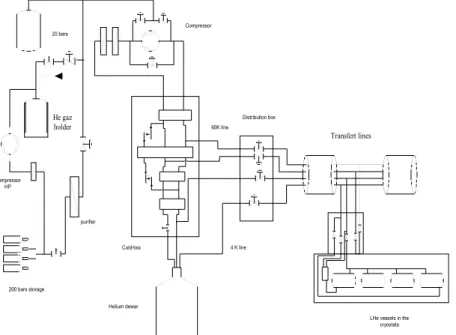
Cryogenic Plant
The LINAG-I cryogenic system will have to supply 44 superconducting resonators mounted in 11 cryostats (a group of four resonators and a superconducting solenoid per cryostat). Cavities and solenoids are operated at 4.2K and cooled by means of liquid helium provided by an on-line liq-uefier-refrigerator system.
The liquid helium produced from the last stage of the cold-box (J-T valve), is stored in a dewar before transfer to the cryostats.
Cryogenic transfer lines can use a coaxial-shield configuration, or four independent pipes super-isolated in vacuum. Each cryostat can be fed independently from a local distribution box by cryogenic valves (liquid-He inlet and returning gas, gaseous-He inlet at 60 K and return). This configuration allows removal of a cryostat with-out interrupting the cryogenic distribution. The return circuits are connected to the cold-box and to a storage gas circuit.
Beam dynamics
Two types of beam dynamics calculations have been performed. The first one [ref.16], using the code TRACK [ref. 17], has been performed at Argonne, in order to show the feasibility and the performances of the SC linac. 3D field maps of the Legnaro type QWRs, calculated with Micro Wave Studio, are used for the beam dynamics calculations W @ 4.2K (with a safety factor of 40%). For the thermal
shielding an average value of 0.5 kW @ 60K will be neces-sary. If gaseous helium is used for pre-cooling operations, an average value is 1.5 kW @ 60K.
The cryogenic plant is composed of a cold-box mod-ule, the cryogenic distribution system, and a gas storage cir-cuit (figure IV.11). A screw compressor compresses the heli-um at 16 bars and sends it to the cold-box for refrigeration. An outlet from the cold-box at 60K (provided from the first turbine of the refrigerator) can be used to cool the cryostats and transfer lines thermal shields (gaseous helium at 7 bars). With a slight reduction in efficiency of liquid helium produc-tion (~5%), this soluproduc-tion avoid the need for liquid nitrogen for the thermal shields.
Cavity dynamic losses 10 W/cavity 44 440 W
Cryostat static losses 5 W/ cryostat 11 55 W
Cryogenic lines static losses 2 W/m 44 88 W
Cryogenic power requirement at 4.2K
LHe vessels in the cryostats Transfert lines Helium dewar Cold-box Compressor 60K line 4 K line Distribution box 20 bars 200 bars storage purifier Compressor HP He gaz holder
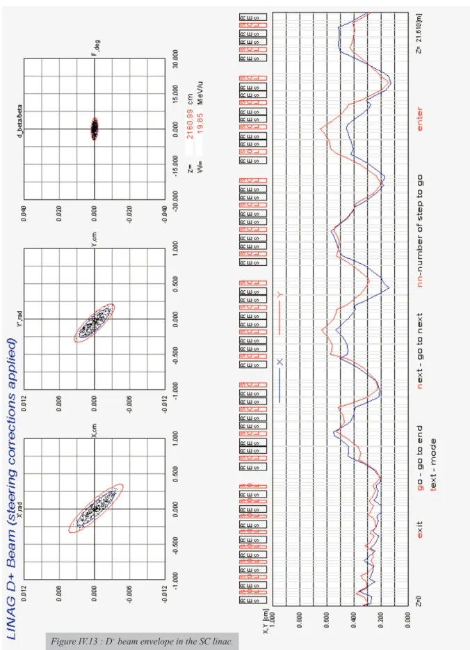
(including all the field dissymetries proper to these cavities and magnetic fields), so that the QWR steering effect is taken into account [ref. 18, 19]. Accelerating fields of 6 MV/m are considered. The space charge effects are not included in the calculations ; according to the experts in SC linacs, they should not be a problem for a 5-mA beam, this point is being checked. Halo and error simulations are being study in details [ref. 20]. The solution is based on quite a high number of solenoids, and figure IV.13 show the beam envelopes for the full emittance beam.
Another type of solution is under design, with a lower number of solenoids, and a structure containing short-er cryostats (“Legnaro” type cryostats). Even if the calcula-tions are still in progress, this second solution has been con-sidered for the cost evaluation, just because the prices and cryogenic performances of the “Legnaro” type cryostats were precisely known. The remaining uncertainty concerns the exact number of solenoids, which will not greatly affect the total price of the SC linac.
Tuning procedure
The first high intensity beam tests will be performed with H21+or He2+beams, before accelerating a D+beam. The
SC linac and the RFQ are tuned first with a low intensity CW beam, by inserting a rotating pepper-pot in the LEBT line. This pepper-pot is connected to a remote-handling system, for the case of activation by the deuteron beam. The cavity phases are tuned one by one, on intermediate time-of-flight
diagnostics (those placed in the inter-cryostats drifts) or by using the cavity as a beam phase monitor, and the sole-noids are tuned using beam profile monitors. The cavity phases can also be tuned by an energy measurement after magnetic deviations placed regularly along the SC linac. (This option has not been retained for the cost evalua-tion). The intensity is then increased slowly, step by step (by rotating the pepper-pot), and parameters are optimised at each step, using then non-interceptive diagnostics.
Medium Energy Beam Transport (MEBT)
The Medium Energy Beam Transport line has not been designed in detail, but we have chosen to include an analysing section in order to retain the possibility of easy addition of a second RFQ injector in future. The transverse and longitudinal beam matching are performed respectively by quadrupoles and rebunchers (1 or 2). The layout of this line is presented in section (e).
Components Comments Unit price (k€)
Cold-box 800W@4K (with compressor) 1300
Helium dewar 2000 litres 30
Distribution box 60
Transfer lines 180
Local distribution boxes 10 units 165
Gas vessel 20 bars – 50m3 50
Gas holder 50 m3 20
Compressor 200 bars – 50 m3/h 50
Storage 200 bars – 12 m3 60
Purifier Cryogenic 100
Pipes and valves 20
Gas analyser 30
Installation 12 man-months 100
Total 2165
SC LINAC: Cost evaluation (without cryogenic plant) k€
1 cryostat , assembled and including vacuum pumps (35 or 25 k€ depending on same or separated vacuum) and thermometry
230 4 Nb/Cu QWR with slow tuner, coupler, pick-up, connectors etc. 100
4 circulators or extra-cost for variable power coupler 60
4 directional couplers and transmission lines 30
1 solenoid with liquid-He housing and power supply 60
1 cabinet of control electronics for the QWR 40
4 5 kW, RF power amplifiers with 100 W preamplifier 200
Cost of the single module for 4 MV, 5 mA and focusing 720
MEBT (≈10 m+ rebuncher) 610
10 inter-cryostat transfer line 210
TOTAL SC LINAC (44 MV, 5 mA, focusing, transfer lines) 8740
Cost evaluation IV.5) LAYOUT OF THE DRIVER
Figure IV.14 : Layout of the driver. Cost evaluation
IV.6) REVIEW OF THE DRIVER COST EVALUATION.
The following table present a review of the costs of the differents parts of the driver. The additional electrical
power needed for the operation of this driver is around 1,5 MW. This power is available at GANIL electrical power sta-tion input, though it would be necessary to adapt the electric-ity distribution.
Cost in k€
D+ source 185 LEBT 275 RFQ 2635 SC LINAC: MEBT 610 CRYOMODULES (11) 8130 CRYOGENIC PLANT 2150 DIAGNOSTICS 400 COMPUTER-CONTROL 400 TOTAL 14785References
1) Compte rendu de réunion du 18 mars 2002, R. Gobin, R. Ferdinand, R. Duperrier, P. Lehérissier, et C. Barué. 2) Détermination et caractéristiques des sources d'ions pour LINAG, Document de synthèse, P. Lehérissier, C. Barué 3) R. Duperrier, R. Ferdinand, R. Gobin, M. Painchault, DSM/DAPNIA/SACM 2002/19, Rapport d’étape du projet LINAG. 4) M. Martone et al, RT/ERG/FUF/96/11, IFMIF Conceptual Design Activity Final Report
5) F. Varenne, GTM/NOTE/LINAG/06-05-02/FV/003, internal report on D+ LEBT 6) F. Varenne, GTM/LINAG/NOTE/01-02-02/FV/001, internal report on ions LEBT
7) M. Di Giacomo, GTM/LINAG1/NOTE/20-03-02/MDG/001, Considérations sur la technologie du RFQ, internal report 8) R. Duperrier, D. Uriot, RFQ beams dynamics studies in favor of the LINAG project, CEA/DSM/DAPNIA/SACM internal report, may 2002.
9) M.P. Kelly et al., Superconductive RF activities at Argonne National Laboratory, Proccedings of the 10th Workshop on RF Supercontivity, Tsukuba, 2001
10) A.M. Porcellato et al., Operation Experience with ALPI Resonators, Proceedings of the 10th Workshop on RF Superconductivity, Tsukuba, 2001
11) A. Facco et al., Superconducting RF Activites at LNL, Proceedings of the 10th Workshop on RF Superconductivity, Tsukuba, 2001
12) S. Takeuchi et al., Nucl. Inst. Meth. A382, 153-160 (1996)
13) J-L. Biarotte, “Flexibilité en puissance de LINAG, internal report IPNO. 14) J. Lesrel, IPNO, Note interne : Etude préliminaire des systèmes RF de LINAG 1
15) L. Dalesio, EPICS: Recent applications and future directions, Proceedings of the 2001 PAC, Chicago, 2001 16) P. Ostroumov, ANL, private communication
17) P. Ostroumov, TRACK: a code for beam dynamics simulation in superconducting linac with 3D electric and magnetic fields, Technical Note, March 2002
18) P. Ostroumov, K. Shepard, ANL, Correction of beam-steering effects in low-velocity superconducting quarter-wave cavi-ties, Physical Review Special Topics, Accelerators and Beams, Vol.4, 110101 (2001)
19) A. Facco, V. Zviagintsev, LNL, Study on beam steering in intermediate-b Superconducting quarter-wave resonators, Proccedings of the 2001 Particle Accelerator Conference, Chicago, 2001
20) J.M. Lagniel, Halos and chaos in space charge dominated beams. Proceedings of the 1996 European Particle Conference, Barcelone (1996).
LINAG phase I
Chapter V : The Target and Ion Source
T
he LINAG phase-I project offers the possibility of pro-ducing intermediate-mass radioactive ions by neutron-induced fission – using a 40 MeV deuteron beam – or other reactions, such as fusion-evaporation and transfer. Moreover, two alternative possibilities can be used for pro-ducing fission fragments, by directly bombarding a uranium carbide target with a beam of deuterons or another heavier ion, or indirectly with neutrons from d-n converter. In this chapter, we will discuss in detail only the converter tech-nique, which is considered the most reliable option for achieving the required number of fissions per second in the uranium carbide target.The principal specifications chosen for the produc-tion system are shown in the following table :
The choice between different technical solutions for the production and automatic handling system has been dic-tated by the security and safety conditions around the target. From these considerations, an automatic handling system has been chosen based on the known “target-plug” technology – as will be described in the following sessions – used success-fully at ISIS, RAL [ref.1], ISAC, TRIUMF [ref.2] and other high intensity beams in fixed-target facilities.
V.1) THE PRODUCTION OF FISSION FRAGMENTS
The technique proposed for LINAG phase-I has been already discussed in the SPIRAL-II EU-RTD report [ref. 3], consisting in the use of energetic neutrons to induce fission of 238U. The neutrons are generated by the break-up of
deuterons in a thick target, the so-called “converter”, of suf-ficient thickness to prevent charged particles from escaping. The energetic forward-going neutrons impinge on a thick production target of fissionable material, i.e. Uranium carbide UCx. The resulting fission products accumulating in the target diffuse to the surface from which they evaporate, are ionised, mass-selected, eventually charge-bred and
final-ly post-accelerated. This method has several advantages. The material of the highly activated converter can be chosen to withstand the power of the beam without constraints con-cerning the diffusion of radioactive atoms. Moreover, the temperature of the converter does not affect the neutron flux. As projectiles, neutrons do not contribute to the heating of the target material directly, nor of the entrance window, which can therefore be very thick, and they do not present any spe-cial security issue. Neutrons bombard the target, losing ener-gy mostly in useful nuclear interactions. They also have a high penetrating power, which allows very thick targets to be used.
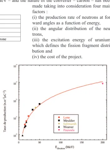
The choice of the deuteron bombarding energy – 40 MeV – and the nature of the converter – carbon – has been made taking into consideration four main factors :
(i) the production rate of neutrons at for-ward angles as a function of energy, (ii) the angular distribution of the neu-trons,
(iii) the excitation energy of uranium, which defines the fission fragment distri-bution and
(iv) the cost of the project.
Figure V.1 : Production of neutrons at forward angles.
Primary beam energy (Deuterons) 40 MeV Maximum primary beam power 200 kW
Fission rate in the target > 1013 fissions per second
Reliability of the production system 3 months
Ion production 1+ close to the target
We examine each of these briefly :
(i) The production of neutrons at forward angles is illus-trated in figure V.1, which shows the experimental neu-tron yield at 0° as a function of the incident energy of the deuterons for a Be-converter.
(ii) The strong forward peaking of the yield of high-ener-gy neutrons (see figure V.2) shows that an approach with compact geometry, consisting of a converter to produce the neutrons followed by a second target containing the fissionable material, is well suited to the task.
(iii) The energy distribution of the neutrons produced in the deuteron break-up (that determines the excitation energy of Uranium) is centered at about 40% of the ener-gy of the incident deuterons and has at 0° a width between one-third and one-half of the energy of the inci-dent deuterons.
(iv) The neutron energy and angular distributions are
similar for light converters. The yield for a carbon con-verter is only 30% smaller and it is slightly less forward peaked than for a beryllium converter, and therefore car-bon has been chosen as the converter in our case.
V.1.1) The rotating target/converter
During the studies of SPIRAL-II EU RTD, simula-tions of neutron spectra for several beam-converter configu-rations have been performed with the LAHET high-energy transport code combined with Monte Carlo N-Particle MCNP code for low-energy transport. Deuteron Coulomb dissocia-tion has been added to the more standard processes, the for-ward peaked break-up and direct reactions and the rather
Figure V.2 : Neutron distribution width as a fonction of deuteron energy.
isotropic evaporation of low-energy neutrons [ref. 4]. The simulations performed at GANIL [ref. 3] were compared with experimental angular distributions measured at energies of 80, 160 and 200 MeV for carbon and beryllium converters.
The LAHET-MCNP code reproduces the order of magnitude of the differential cross sections without any adjusted parameter. Some systematic deviations can be noted. Nevertheless, these deviations do not change the conclusions of the simulations, within 30% of confidence level.
The neutron yield is only one of the factors to be taken in consideration for the choice of the converter material. Other aspects in the evaluation are :
i) thermal properties that allow a compact geometry of the converter and the production target,
ii) toxicity and material properties of the converter, iii) production of long-lived radioactive nuclides, and iv) cost of operation.
Our conclusions regarding these aspects are summarised below :
A beryllium converter produces the largest amount of neutrons, however, its low melting point (1278° C), does not allow the use of high-intensity deuteron beams, nor plac-ing of the converter very close to the hot target.
Liquid lithium is a more robust converter with respect to deposited beam power than beryllium or carbon. However, the flow of hot liquid lithium containing some amount of radioactive products requires special care in the design, especially from safety considerations. A converter designed along these lines, originally described by Grand and Goland [ref. 5], is probably not to be considered in the con-text of LINAG phase I, but could be of interest for a “next-generation” facility, e.g. EURISOL since it can stand extremely high beam power.
The above-mentioned properties clearly favour car-bon as converter material. It is non-toxic, easy to handle and has a high melting point of 3632 °C. These excellent proper-ties allow high beam intensiproper-ties with a rotating wheel cooled mainly by thermal radiation.
For LINAG-I the main parameters of the rotating carbon wheel have been obtained by simulations using the code SYSTUS [ref. 6]. The quality of the carbon has been chosen for its conductivity. POCO [ref. 7] graphite PLS has a thermal conductivity exceeding 40 W/m°C at high tempera-tures. This is important for reducing the size of the wheel. For the simulations, an infinite rotation velocity was used, in a first approach. Once the main characteristics were chosen, the temperature variation with respect of the beam impact was calculated for a real angular velocity of 1000 RPM. The
V.1.2) The target and ion source produc-tion system
The target and ion source produc-tion system is placed just behind the rotat-ing carbon converter. With 1 x 10¹³
fis-sions per second, the total power produced in the UCxtarget is 310 W. As mentioned above, the production target is not influ-enced by the primary beam. The target temperature is completely controlled by an independent heating system, with a power of about 5 kW.
thermal shock for which graphite achieves the ultimate strength (break-down condition) is for about 50°C in our con-ditions, therefore a maximum temperature variation of 20-30°C per revolution has been considered. The results of four different calculations are presented in table V.1. In the first column, the internal and external radii of the wheel are quot-ed with its total weight. In the second column, the mean beam radius and the vertical size of the beam is indicated – the hor-izontal size has been taken as 10 mm in all calculations. The maximum converter temperature is shown in column 3 and the temperature variation over one turn is quoted in column 4.
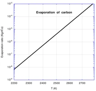
The evaporation ratio of the carbon is dependent of the graphite saturated vapour pressure. Experiments per-formed at GANIL and IPN-Orsay [ref. 8] for a specific car-bon from POCO and Carcar-bon Lorraine industries show that the evaporation ratio of carbon is in agreement with the val-ues found in literature. The evaporation rate obtained experi-mentally is shown in the figure V.3. The evaporation rate for
evaporating 1 mm thickness of the carbon wheel in a period of 2000 hours is 2.6 x 10⁻⁷ kg/m2s. It corresponds to a
tem-perature of 2085°C. This consideration fixes the sizes of the wheel and the beam spot on the carbon converter; i.e. 350 mm of radius for a beam spot of 10 x 35 mm.
The precise size of the beam can be achieved by applying a fast scanning of the beam in one direction and/or by having an angle in the converter. We suggest the solution with a beam profile such as 10 x 30 mm with a converter angle of 30°. A sketch of the converter-target design is shown in figure V.4, for two alternative configurations.
A similar study with equal results [ref. 9] has been made in the framework of the SPES project, Legnaro, Italy. The difference between both projects is that, in the latter case, the beam considered was proton of 10 MeV, with a total beam power of 100 kW.
Rint Rext converter
(weight)
Xbeam = 10 mm
(scanning target) Tmax target
∆T (with w=1000tr/mn) 290-350mm (1.5kg) 320mm (20mm) 2280°C 33°C 290-350mm (1.5kg) 320 (30mm) 2120°C 22°C 290-350mm (1.5kg) 320 (44mm) 2000°C <20°C 340-400mm (1.75kg) 370mm (20mm) 2160°C 29°C
Table V.1 : Maximum target temperature with different target radius and different sizes of beam scanning.
1 0-9 1 0-8 1 0-7 1 0-6 1 0-5 1 0-4 1 0-3 2200 2300 2400 2500 2600 2700 Evaporation of carbon Eva p o ra ti o n ra ti o (Kg /m 2.s) T (K)
Figure V.3 : Carbon evaporation rate.