Design of an Exportable Digital Design
Curriculum
by
Christopher M. Cacioppo
B.S.E.E. Electrical Engineering
University of Connecticut, 1994
SUBMITTED TO THE DEPARTMENT OF ELECTRICAL ENGINEERING IN PARTIAL FULFILLMENT OF THE REQUIREMENTS FOR
THE DEGREE OF
MASTERS OF SCIENCE IN ELECTRICAL ENGINEERING AT THE
MASSACHUSETTS INSTITUTE OF TECHNOLOGY JUNE, 1996
© 1996 Massachusetts Institute of Technology. All rights reserved.
Signature of Author:
S urp ment of Electrical Engineering May 10, 1996
Certified by:
/ Donald E. Troxel
Professor of Electrical Engineering Thesis Supervisor Accepted by:
lFr1ric R. Morgenthaler
SChai
a'n, Committee for Graduate StudentsDesign of an Exportable Digital Design
Curriculum
by
Christopher M. Cacioppo
Submitted to the Department of Electrical Engineering on May 10, 1996 in Partial Fulfillment of the Requirements for the Degree of
Master of Science in Electrical Engineering.
ABSTRACT
A digital design curriculum has been developed that is applicable to a wide range of teaching situations. The main focus is on the basic principles of digital design. Economy of effort is achieved by focusing on a single goal that is built up over a number of labs. The chosen goal is a
simple game called NetPong, which not only presents information on the basic digital design concepts, but also introduces information on networking and common interfaces.
The materials associated with this curriculum include six lab manuals with associated prelabs, custom software, and sample solutions. This material is not intended to be a complete course, but it should be sufficient for someone knowledgeable about digital design to quickly put
together an introductory course. The material is adaptable to a range of audiences and can easily be tailored for different audiences, from advanced high school students to junior level college
classes. Furthermore, minimal equipment requirements were chosen to allow programs with more moderate funding to be able to use this material.
Thesis Supervisor: Donald E. Troxel Title: Professor of Electrical Engineering
1. Statement of Problem ... 1.1 No lab progression: ...
1.2 Not enough emphasis on design: ....
1.3 No lab manual/text:... 1.4 Not suitable for exportation: ... 2. O verview ...
2.1 W hat is provided ... 2.2 H ardw are ... 2.3 Softw are ... 2.4 Lab M anuals ... 3. Hardware Approach and Issues ...
3.1 Requirements ... 3.2 Solution ... 3.2.1 The goal ... 3.2.2 Networking ... 3.3 Components ... 3.4 Documentation ... 4. Software Approach and Issues ...
4.1 Requirements ... 4.2 Solution ... 4.2.1 Design Philosophy ... 4.2.2 C++ Advantages:... 4.3 Components ... 4.3.1 The Hub ... 4.3.2 The Ports ... 4.3.2.1 Player ... 4.3.2.2 Comm PortMaster 4.3.2.3 Comm Port Slave 4.3.2.4 Logger ... 4.3.2.5 Video ... 4.3.3 GenComm ... 4.3.4 PITSpeed ... 4.3.5 M essage ... 4.4 Documentation ... 4.4.1 Hardware Requirements .... 4.4.2 User Documentation ... 4.4.2.1 Setup Options .... 4.4.2.2 Run-Time Controls . . . . . . . . . . 6 . . . . . . . . . . 6 . . . . . . . . . . 7 . . . . . . . . . . 7 . . . . . . . . . . 8 .. 9 . . 9 .10 10 10 10 11 11 ...1 8
5. Lab Manual Design Issues ... 18
5.1 Requirements ...
18
5.2 Solutions ... 19
5.2.1 Prelabs...19
5.2.2 Structure ... ... 19
5.2.3 Design information background ... 19
5.2.4 Clear Presentation of Assignments ... 19
5.2.5 Design before building ... 20
5.3 Components...20
5.3.1 LabCoverage ... 21
5.4 Documentation...22
6. Lab M anuals and M aterials ... 23
6.1 Overview ... 25
6.2Prelab l&Lab 1 ... 29
6.3 Prelab 2 & Lab 2 ... 39
6.4Prelab 3 & Lab 3 ... 47
6.5 Prelab 4 & Lab 4 ... 55
6.6Prelab 5 & Lab 5 ... 71
6.7Prelab 6 & Lab 6 ... 81
6.8 Suggested Enhancements ... 93
7. Conclusion ... 95
8. Bibliography ... 96
1. Statement of Problem
The goal of this project was to design a new digital design course which will provide solutions to a number of identified shortcomings of MIT's current course (6.111)1. The issues to be addressed are as follows: no lab progression, no lab manual or text and too little emphasis on design issues. In addition, the exportability of the current course is very limited. I will address each of these points individually. The approach taken was not to 'fix' the current course, but to create a new one which teaches much of the same material in a new manner.
1.1 No lab progression:
In the current implementation of 6.111, there are three project labs, each requiring students to build a project from scratch. Each of the labs require a significant amount of time on the part of the students, each getting progressively more difficult. Unfortunately, a large portion
of this time is spent rebuilding basic building blocks learned in previous labs. In order to address this problem, I designed a course that has a single structured lab goal that the students work on in stages throughout the term. Each lab is built upon the previous one. The amount of components that are built and then torn down is restricted to those that are needed for testing. This will satisfy a number of goals. First, the students will spend less time rebuilding things that they already understand. Second, it will provide the students with a definite goal; they will be able to see why each lab is important and how it is allowing them to progress towards the defined goal. Finally, it will encourage students to stay on track, as each lab will be necessary for subsequent labs.
1.2 Not enough emphasis on design:
Currently, a lot of time is spent showing the students the basics of how various
components work and how to interface with them. While this is important, little time is spent teaching students how to properly approach engineering decisions and tradeoffs.. There are many design decisions that students are required to make during the course of a project; students often make uninformed decisions or may progress without even realizing that they are making decisions. In my new course, time in each lab section will be spent discussing design principles and carefully looking at the design issues associated with integrating the current lab into the overall project. When appropriate, a number of possible solutions to the problem are presented, weighed against each other and finally the best option chosen. It is emphasized that design is an
iterative process and discourage the "build and patch later" approach that many students take.
'The work for this course was funded by an ECSEL block grant from the National Science Foundation (NSF).
1.3 No lab manual/text:
One of the largest criticisms the students have of the current design course is that there is no lab manual or text that is available for their use. The required book for the current course is the TTL Databook, which focuses on specific implementation issues and not on overall design. The students rely heavily on the lecturer and TAs for information on the labs. A large portion of this project was devoted to creating a lab manual presents the material of the course in a coherent
and straightforward manner. This will be a great asset to the students and will complement regular lectures well.
1.4 Not suitable for exportation:
Although this is not technically a problem, it would be an asset to a course if it were exportable to other schools. Exportability brings up two major issues: equipment and level of course material. MIT students are fortunate that their university has a large amount of state-of-the-art equipment. This allows the students to design complicated systems with relative ease
compared to many schools which do not have these facilities. In order to make this course functional, as well as much more accessible to different schools, I have focused it for schools with mid-range facilities. I am assuming that all of the schools will have access to basic
equipment: entry level PCs, low bandwidth oscilloscopes & logic analyzers, and some basic PAL and PROM programmers.
The second issue is the level of the course material. In order for the course to be exportable, it had to be very flexible and be taylorable to audiences with various educational levels.
2. Overview
2.1 What is provided
As previously stated, the purpose of this project was to provide materials that would be suitable for putting together a digital design curriculum. This is not intended to be a turn-key system; instead, it is a collection of materials that will allow someone with a background in digital design to rapidly put together a course suitable to teach the concepts of digital design to students. There is a significant amount of flexibility that the instructor has in molding the course to be most suitable for his students. The flexibility comes from optional assignments, high level design decisions and further suggested enhancements.
The approach that is taken with this material to teaching digital design is to have the students build a significantly complicated digital system, one piece at a time. The overall goal of the project had many requirements from a digital standpoint, but it also had a number of requirements from a more general standpoint. The students were going to be working on the project for a significant amount of time (the exact amount depends upon the instructor) and it
was important to keep the students' interest throughout that time. The net result of the search to fulfill all of the requirements was a game called NetPong.
NetPong is a multiple player version of the classic game of pong. The basic premise is that there is a ball that moves around a 64 X 64 screen. Each player has a paddle that is
positioned on one side of the screen. Their job is to keep the ball in play by moving their paddle to block the ball from falling off their side of the screen. If the ball falls off the side of the
screen, it is placed back in the center and play starts again.
2.2 Hardware
The main purpose of this lab sequence is to teach the concepts of digital design. In the course of the lab sequence, the students will work with basic units such as UARTs, SRAMs, A/Ds and D/As. Furthermore, they will be controlling their system using Finite State Machines (FSMs) and Micro Control Units (MCUs). In addition to actually building the hardware, they will be responsible for writing the necessary microcode (-500 lines of code), though the
professor may want to provide a portion of this code to the students. Although there is a lot of necessary structure in the lab, there are flexibilities that the students have when accomplishing their individual projects.
It is suggested that the students build their projects on bread-boards. In addition, the students will need to have access to basic oscilloscopes, logic analyzers, PROM and PAL
programmers. The equipment can be low end or older equipment, as the suggested system clock speed will be less than 200KHz.
One of the most basic elements of NetPong is the network which enables communication between the students. The network is a simple hub-based star network which utilizes UARTs for all input and output. There is only a little extra work that is necessary on the students' part to properly interact with the network. The students will gain some valuable knowledge about networking while building and utilizing the NetPong network.
2.3 Software
The software for the course is written in C++ and is intended to run on an IBM compatible PC platform. This was chosen because many universities use this platform, as it is low cost compared to most UNIX workstations. Source code is provided, therefore, if it is desirable, this software can be ported to a UNIX environment. See section 5. Software for more details. The PC requirements are moderate; for specific details see 5.1 Software
Requirements.
The role of the software is to monitor the network and provide a number of services to the students. The software will provide a video display for the students so they can quickly be provided with visual feedback. This also eliminates the need for students to build their own video which is a reasonably complicated project and involves higher bandwidth scopes and analyzers. In addition to video, the software can add artificial players if less than four human
players are available. Furthermore, the software provides logging of network messages for debugging purposes.
The architecture of the software is similar to the hardware that the students will be designing. At the heart of the software there is a software hub which acts in a similar manner to the hardware hub. All of the software elements, such as the video display, communication port interfaces, message logger and artificial players, are ports that can be 'plugged into' the software hub. All of these ports have identical software interfaces which allow them all to be treated the same. All of the 'plugging in' of modules is controlled by command line switches or commands placed in the environment variable NETPONG. Student Kit #1 Computerpaer #1 Video Unit Player #1 /I
Hardware Slave Comm Software
Hub Port Hub
- b
Student Computer Message
#2 Player #2 Logger
Hardware
Software
There are a number of options that the instructor can decide upon that will directly influence how the network will operate. These options include the size (in bytes) and format of the messages and the format of each transmitted byte. In order for the software to accommodate all the possibilities, a flexible configuration is necessary. This results in a significant number of options that can be specified on the command line or in the NETPONG environment variable. Section 5.4 Software Documentation has specifics on the various options.
In addition to the software that was specifically made for the course, there are a number of tools that were developed at MIT for FSM and MCU microcoding purposes that will assist the students in their design. More information on these tools are provided in section 5. Software
2.4 Lab Manuals
Probably the most valuable resource that is provided is the sequence of six lab manuals that guide the students through the design and development of their NetPong kits. The lab manuals are not intended to be the sole source for information for the course. Instead, they are expected to be accompanied by lectures and/or a formal text on digital design. Furthermore, the students should have available a TTL data book and specification sheets on the various parts they will be using.
There are two major ways to learn material: self learning and instructed learning. Self-learning is the process where students figure out concepts and issues for themselves. Instructed learning is when concepts and issues are directly presented to the students. In general, self-learning results in a greater long term comprehension for the students. The advantage of
instructed learning is that we can make sure that all of the concepts are adequately covered. This lab sequence tries to strike a compromise through a directed self-learning approach. Each lab is accompanied by an associated prelab. The prelabs present one or more high level digital design
issues that are relevant to the upcoming lab. The students should be required to generate solutions to the issues presented. In the actual lab manual, there is a discussion of the prelab questions and suggestions are made as to the best possible solution(s) for the design of NetPong. Some solutions must be followed or they will significantly change the structure of NetPong. Some suggestions should be decided upon by the instructor as the decisions will effect the entire class. Finally, there are some decisions that only affect the individual student's kit and they are thus free to chose the solution of their choice. These three different levels of freedom in the suggested solutions are clearly marked in the text.
3. Hardware Approach and Issues
3.1 Requirements
There were a number of major issues associated with the hardware. The three most important design considerations were:
1) Teach major digital design concepts (UART, FSM, MCU, A/D, D/A, SRAM, PROM) 2) Be able to break up the project into completable, mostly stand-alone, projects.
3) Be interesting to the students
In addition, the following design ideas were desirable, though not necessary:
1) Teach how to work with a standard interface: In today's working environment it is very rare that an engineer is designing an entire system by themselves. Instead, most of the time engineers are working in teams and must design systems that interact with each other and also interact with off-the-shelf designs. It is for these reasons that I believe that this skill is very important.
2) Promote working together: In addition to just designing system interfaces that match up, it is important that students get some experience working directly with one another on a reasonably difficult task. This is also an invaluable skill.
3) Teach basic networking: Networking is a technology that has significantly grown in importance recently. Many aspects of engineering are directly or indirectly involved with networking. Understanding some of the basic issues of networking will also be a valuable asset to the students.
4) Spend less time building and tearing down: The current course at MIT that teaches digital design requires a tremendous amount of the student's time. Some of this time is necessary, but a good deal of time is spend building and tearing apart and rebuilding systems. A goal of this project was to maximize the amount of useful time the students spend on the course.
3.2 Solution
NetPong was conceived as a solution to all of the above requirements. The NetPong project is broken up into six progressive labs that the students will complete. In addition, NetPong is inherently an interactive project, with the finished goal being a simple multi-player game of pong. The students have to interface to the custom network on both a digital level and at a simple protocol level. In addition, because they are progressive labs, very little hardware has to be built only to be torn down again later. For more information on the hardware in the lab was put together see section 4.3 Components.
3.2.1 The goal
The goal of this lab sequence is to build hardware that can act as a player in the game of NetPong. The game aspect should keep the students' interest more than many less interactive projects could. The actual game play will be much like the well known game of pong.
Each students will have a paddle on one side of the
I
screen. As the ball bounces around the screen it is theplayers job to make sure the ball doesn't fall of their side
of the screen. They have to use their paddle to deflect
I
their ball into another direction.. The actual mechanics of the game are as simple as possible so that the students
\
can concentrate on hardware rather than complicated
microcoding..
-Figure 1: NetPong 3.2.2 Networking
The heart of NetPong is a simple network that the students build. To keep the complexity of the network down, it is made up of UARTs and does not require any special purpose analog hardware. Some basic ideas of low level networking are introduced in the earlier labs. In the later labs when they are working with the MCU, higher level networking problems are proposed, presenting such things as synchronization and auto-assignment of network IDs (i.e. player numbers).
3.3 Components
The hardware was designed with the intention that we want the students to build it in small pieces. In addition, the sequencing of the labs was such that simpler concepts were presented before more complex ones; this is especially important when one concept is based upon another. For example, FSMs should be presented to the students as simple controllers before MCUs are discussed. For the most part, each of the six labs present one part of NetPong, although a few present more than one.
3.4 Documentation
There are, of course, many possible solutions to the hardware that will result in a fully functional NetPong project. Therefore, it is impossible to come up with a fully comprehensive solution set. Instead, the author designed a working solution that is fully documented in Appendix A. Depending upon the level of the audience, parts of this solution may want to be distributed to the students. In fact, there is a lot that can be learned about digital systems by distributing the provided solution and having the students making the system work.
4. Software Approach and Issues
4.1 Requirements
It was decided that in order to reduce the complexity of the labs, a computer would be used to monitor the network and provide a video display based upon the messages. Furthermore,
once a computer is attached to the network, it becomes convenient for it to generate auto-players to fill in for players who are missing. In addition, it was useful for debugging to have some sort
of message logging feature.
4.2 Solution
The two major decisions that are made when writing a program are the general approach to the problem and the language that will be used. These two decisions are often related. The first issue is covered in 4.2.1 Design Philosophy and the second issue is covered in 4.2.2 C++ Advantages.
4.2.1 Design Philosophy
The original software written for this course was done exclusively to test the hardware concepts and the networking protocol for NetPong. As a hardware test was the goal, the
software was written in modules that closely resembled the hardware. There was a software hub, which has a similar role as the hardware one the students will build. Furthermore, there were objects called "players" and "video" that plugged into the hub to test functionality, much like student kits plug into the hardware hub.
When it came time to build the software that the students would be using, it was apparent that the test software was a good base to work from. The interface between the player objects and the hub was generalized so that other types of objects could be plugged into the software hub. Communication objects were added, as well as message loggers. Furthermore, a complicated configuration system was added to provide a large amount of flexibility. Finally, hardware timers were implemented so that the software would work the same independently of the speed of the machine it was being used on.
4.2.2 C++ Advantages:
The program was written in C++ to take advantage of the reusability of code and the polymorphism properties of the languages. C++ is a good language for modeling systems, due to its class structure, so it was used to build the first simulation of the NetPong design. After this, code reusability was an issue because I could use the code from the original simulation I had already created. In addition, a communication object called GenComm (see 4.3.3 GenComm) was previously written, I was able to reuse the code with some modifications. Polymorphism was useful in creating 'ports' which plugged into the software 'hub' with the same interface. This made the program easier to understand, and also helped in making the configuration options very flexible. The down side to using C++ is that it is not quite as portable as ANSI C.
4.3 Components
The NetPong program is made up of a number of important objects. Each object that was built is described in this section.
4.3.1 The Hub
The hub is the software equivalent of the hardware network hub. It keeps track of the various ports and distributes messages between them. It also passes tokens to each port to indicate that the port has control of the network and is now able to transfer data. The interface between the hub and each of the ports is identical in all respects except for initialization.
As in the hardware hub, the software hub provides a virtual network token to all of the ports in a round robin fashion. This is done by the hub calling the token function for the appropriate port. When the port is finished with the network token, it returns from the token function. Messages are sent by the ports by calling the send function of the software hub. Every time a message is received by the software hub it, in turn, sends the message to all of the
ports attached to it (with the exception of the sender) by calling the function called parsemsg. The sender is excluded here to prevent the echoing of messages.
4.3.2 The Ports
The following objects are all derived from a single virtual object called npport. This base object contains all the virtual functions needed to interact with the software hub.
4.3.2.1 Player
The player object is essentially one artificial player. The artificial player's paddle will generally follow the movements of the ball. The artificial player has a difficulty setting which determines how often the paddle will miss the ball. Every time the artificial player receives a 'CLAIM OWNERSHIP' message, it determines if the paddle is going to hit or miss the ball.
Once this is determined, the side of the paddle the ball will miss, or the place on paddle the ball will hit is determined. For debugging purposes, if the miss rate is defined as zero, the paddle will act deterministicly and the ball will always hit the paddle in the middle.
4.3.2.2 CommPortMaster
The comm_portmaster is used when a kit will be directly attached to the computer without the use of an external hub. This will enable the student to test an individual kit without being concerned about whether or not the hardware hub works correctly. This object will take care of all I/O through the serial port.
4.3.2.3 Comm Port Slave
The commportslave is very similar to the comm portmaster. It will be used when the computer will be attached to the network hub, instead of directly to a single kit. This will enable the computer to provide video, players to a standard game.
Slave
Computer Serial Port .. .. .I -. . HubMaster
Computer Serial Port e RS-232 eciever/Transmitter Kit Kitmessage logging, and artificial
4.3.2.4 Logger
The message logger takes all of the messages that it gets from the software hub and logs them to a user specifiable file. The data can either be saved in a tab separated raw format for analysis with other programs or it can output verbose message information. The main purpose of this object is to provide high level debugging information for the students.
4.3.2.5 Video
The video unit is responsible for receiving messages from the software hub and displaying information on the computer screen. In addition to displaying the location of the paddles and the ball, the video unit tracks and displays network statistics. The last person to claim the ball has his paddle colored red. Furthermore, two statistics, network messages per second and tokens received per second, are tracked and displayed.
4.3.3 GenComm
This is a communications object that is used in both commport_master and
commport_slave port objects. This object was based upon a communication object previously written for an undergraduate senior design project, but was significantly rewritten to remove
bugs and make a more general interface. This object takes care of programming the UART and servicing all of the serial port interrupts. The incoming and outgoing data is stored in two separate queues that are easily accessible to the programmer through the object's functions.
4.3.4 PITSpeed
The PITSpeed object was designed as a solution to acquiring a hardware timer on a PC. It was very difficult to obtain a suitable hardware timer on the PC platform. There is only guaranteed to be one hardware PIT (Programmable Interrupt Timer) for each PC. Each PIT has three individual timers. In the PC, timer 0 is used for the system clock and causes interrupt 08h, timer 1 is used for the DRAM refresh, and timer 2 is used for generating tones for the speaker. We can not reprogram the DRAM refresh without possible severe consequences and using timer 2 would aggravate the users by having lots of aggravating tones coming out of their speakers. The solutions would have to be based upon timer 0 (i.e. the system clock). Unfortunately, the system clock is refreshed approximately 18 times a second, which is very slow for the timing requirements we need. The solution was to reprogram the PIT to a faster frequency. Normally, this would cause problems with the system clock and anything else that was using the timer interrupt. In order to correct for this an interrupt handler was placed at the top of the interrupt chain for Interrupt 08h. The interrupt handler only passed on a fraction of the interrupts that it received to correct for the appropriate speed change. For example, if we sped the PIT up eight times, the interrupt handler would only allow one out of eight interrupts to actually pass. This now provided us with an interrupt at appropriate speeds and also preserved the system clock.
4.3.5 Message
The Message object is a collection of data associated with a message, including sync character, player number, message id, and data fields. This is used more like a data structure than an object, but it was convenient that it would allocate space and initialize itself to default values when created with the 'new' function. All of the formatting modifications for
transmission are done at transmission time, and therefore the programmer does not have to worry about them when using this object.
4.4 Documentation
4.4.1 Hardware Requirements
It was chosen that this software should run on an IBM compatible PC. This choice was made because this platform is inexpensive and is often available in many school labs. The
software should work on a 286 or better class of machine. It has, however, only been tested on a 486 class machine. Furthermore, it is necessary that the PC has a VGA display and a serial port so that it can connect to the network.
4.4.2 User Documentation
There are two types of commands that the NetPong program will accept: Setup Options and Run-Time Options. Setup Options are options provided to the program as it begin execution and will setup the way the program works. Setup options can either be placed in the
environment variable NETPONG' or put on the command line when executing NETPONG. Command line arguments will override arguments that are placed in the environment variable. Run-Time options are commands that the user can execute while the program is running.
4.4.2.1 Setup Options
All setup commands are to be preceded with a '' character. If a setup command is invalid, the program will fail and specify which argument is invalid. All character options can be provided in either upper or lower case. Between each command there should be one space, however, command parameters should follow the commands without any spaces.
For example: netpong /s /p2 /lbci
or alternately: set NETPONG /s /p2 /lbci
netpong
will start netpong in slave mode with two artificial players. In addition, the message logger will be enabled to store all ball moves, claim ownership, and initiate player messages.
There are a number of areas that the setup options effect: communications port, message logging, message format and misc.
Computer Players:
'P#' This sets the number of artificial players that the computer should add to the game. The valid numbers are 1 through 4. If you have three students kits
attached to the network then you should add one computer player (/P 1). If you specify more artificial players than there are empty spaces then the results are undefined. The default players are one.
'D#' This sets the difficulty of the artificial players. The parameter specified is the 1/10's of a percent that the paddle will miss each ball. The valid ranges are 0-100, which means that the maximum error rate can be 10%. It is random where on the paddle the ball will hit. The only exception is a argument of 0, which will result in a deterministic game where the ball always hits the middle of the paddle. This is useful for testing. All of the computer players have the same difficulty. The default is a difficulty of 0 -deterministic play.
Example:
/D 15 The computer players will have a 1.5% chance of missing the ball every time the ball hits the paddle's side of the screen.
Communications Port:
'M' This sets the communication port up as a master. This is the mode that you want to use to hook a single kit directly up to the computer. Make sure that you have an RS-232 to TTL voltage converter between the two. The default comm type is slave ('S').
'N This disables the communication port. This is only used for software testing. The default comm type is slave ('S').
'S' The sets the communication port up as a slave. This is the mode that is used when you want to attach the computer to the hardware hub. This is the default comm type.
'C# This sets the comm port to use on the PC. The valid numbers are 1 through 4. Comm ports 3 and 4 should work, but were not tested, as no hardware was available to test on. The default comm port is one.
'B#' This sets the baud rate for the serial port. The following speeds are supported: 110, 150, 300, 600, 1200, 2400, 4800, 9600, 19200 and 38400
The default speed is 9600 baud.
'R[1,2,6,7,8,N,E,O]' This sets the various comm port settings, including data bits, stop bits, and parity. The following are the meaning of the options:
1 - 1 stop bit (default)
2 -2 stop bits 6 -6 data bits
7 -7 data bits
8 -8 data bits (default) N -No parity (default) E -Even parity
O - Odd Parity
Message Logging:
'F[name]' This sets the file name for the message logger. If no name is specified then the default file name will be NETPONG.LOG.
'L[#,A,B,C,I,P,R,U,V]' This option enables the message logger and sets the options for the message logger. This option can be enabled multiple times to turn on more options, but can not be used to disable older options. Multiple options can be included after the L option and should all be placed together without spaces.
# The valid numbers are 0 through 9. This option will log the message with the number specified.
A This option logs all messages.
B This option logs ball move messages -both BALLXMOVE and
BALL Y MOVE.
C This option logs the CLAIMOWNERSHIP messages.
I This option logs the INIT_PLAYER messages
P This option logs paddle move messages -both PADDLE XMOVE and
PADDLE Y MOVE.
R This logs RESET messages
U This message logs velocity update messages -both
UPDATE XVELOCITY and UPDATEYVELOCITY.
V This enables verbose message handling. By default the message logging is done in a raw, tab separated form. If the 'V' option is specified then the output will be in a more readable form.
Examples:
/LAV This would log all messages in a verbose format
/L1234 This would log messages with ID#s 1,2,3 and 4 in a raw format.
Message Format:
'/I[+,-]' This argument sets or clears player number and message ID compression. If compression is set then the second byte of the message will contain both the player number and the message ID compressed (the first byte of the message is the sync character). Compression has the upper most two bits represent player number, and the lower bits being message ID. Keep in mind that actual bit locations depend upon the number of data bits that your UART is sending. If there are eight data bits then the compression will look like PPIIIIII, seven data bits PPIIIII, and six data bits PPIIII. /I+ turns on compression and /I- turns it off Compression is off by default.
'/Y#' This argument will specify the character that should be used for the sync
byte. The hex number must immediately follow the 'Y'. (ex, /Y80 would set the sync byte to 80 hex, or 1000 000 binary) The default sync byte is FF hex.
Misc:
T#' This argument sets the speed of the interrupt counter. The valid numbers that can be chosen are 1 to 9. The number corresponds to the speedup over the standard system clock. This is used to clock the counter that times the ball X and Y movement. The numbers directly translate to the following frequencies:
1 36 Hz 4 291 Hz 7 2330 Hz
2 73 Hz 5 582 Hz 8 4660 Hz
3 146 Hz 6 1165 Hz 9 9318 Hz
/T7 would result in a base frequency of 2330 Hz. The default is 6 ( 1165 Hz).
V[+/-]' This option turns the video unit on and off. The network will somewhat faster if the video unit is disabled, but this is normally not of much use if the game can not be seen. This option is mostly used for debugging purposes. The default is video unit on.
4.4.2.2 Run-Time Controls
The run-time options are very limited; currently there are only three.
'r'- Reset: When the 'r' key is pressed, a RESET message is broadcast to all of the ports on the network (both software and hardware ports). This should result in the game being reset.
'q'- Quit: When the 'q' key is pressed the program will quickly exit, closing all of the appropriate log files.
' - Pause: This is a toggle that will pause (or un-pause) the game. The computer will hold onto the token so that the students kits will not continue playing.
5.
Lab Manual Design Issues
5.1 Requirements
The important criterion to address in creation of the lab manual is how to properly convey the information to the students in the most efficient and useful manor. There is an important balance between the superior retention of problems that the students figure out themselves and the extra knowledge that is possible when you directly present information. Furthermore, it is important to keep a consistent structure that the students can be familiar with as they progress through the labs.
5.2 Solutions
There are a number of methods that are used to properly convey information to the students which attempt to maximize the amount of information presented and retained by the student.
5.2.1 Prelabs
Associated with each lab is a prelab, which is intended to be provided to the students before the actual lab. In the prelabs, important design decisions are presented and possible
solutions are proposed. The students should be given ample time to analyze the problems and write up their solutions. The actual labs contain solutions to the prelab questions and explain why the choice made is probably the best for our particular problem.
5.2.2 Structure
The lab is designed to have a consistent structure in which it is easy to identify the
information contained within. At the top of each lab are two sections labeled Object and Topics. The Object contains a list of the piece or pieces of NetPong that will be designed in the particular lab. The Topic section explains the digital design concepts that will be covered. This will allow
students to easily use the previous labs as reference.
5.2.3 Design information background
When the students are in lab, it is often useful to have some easy informational reference to be able to use. Within each lab is a short description of the relevant topics that will be important for completing the lab. This information is abbreviated and is only intended for quick reference or review. There should be a detailed lecture and/or a digital design book which should provide the students with a detailed and formal presentation of the material.
5.2.4 Clear Presentation of Assignments
It is important that the assignments the students are expected to complete are marked clearly. This is done in the lab by having a section titled Lab Assignment, which contained a list of the assignments that were expected to be completed. The prelabs would have been broken up too much if assignments were divided into their own sections. Instead, assignments are clearly marked with a special symbol (c) which the students know to look for. This should prevent possible tension between course personnel and students over the clarity of what is expected.
5.2.5 Design before building
The students are encouraged numerous times throughout the lab sequence to design out the projects fully before building them. This is stated explicitly and also implicitly in the
carefully posed prelab questions and design discussions.
5.3 Components
The sequence of labs contains a consistent format so that the students can easily adjust to one standardized format. Furthermore, the layout enables the labs to be used as reference for the students. The individual sections are as follows:
Prelab: Each prelab is separate from its associated lab which is intended to be handed out before the lab itself The prelabs present one or more significant design decisions to the students. The students are then required to analyze the situations and then suggest and defend a solution to the problem. The design questions to which the students are responding to are marked with the c symbol.
Object: This is the first section of every lab. It is simply a list of the relevant piece(s) of NetPong that will be built in the lab.
Topics: This is a list of the digital design concepts which are covered in the lab. Prelab Discussion: This section discusses the questions proposed in the prelab. If the
design decision affects other kits, then a suggestion is provided that is expected to be followed. If, however, the solution only affects the student's kit, they are free to implement any solution they feel is best. Because this section provides
answers to the Prelab, it is suggested that the labs be handed out after the prelabs so that the students have time to review the design problems and spend time understanding the issues.
Design Issues: This section provides information that is necessary to complete the lab at hand. Many digital design issues are discussed, but this is not intended to be a comprehensive source on all topics. It is intended to be an additional resource, for quick review or preview, that will compliment a digital design text and/or lecture.
Lab Assignment: The lab assignment section contains the actual lab assignments that the students are expected to complete. There are a few assignments that are for educational purposes only and are not strictly necessary for building NetPong. These assignments are marked accordingly.
5.3.1 Lab Coverage
The following is a summary of the topics that are covered in the various labs. These are listed at the top of each lab under the section titled Topics.
Lab 1:
Topics: Clocking, Fanout, Counters, and PALs Object: Gain Familiarity with Equipment
Establish Appropriate Clocks
Designing Network Hub Functional Logic
Description: This lab is intended to get the students familiar with the way labs are set up and how they will progress. The goals here are fairly straight forward and should not take the students a large amount of time. Because of it's importance in making the whole system work, the first thing that the students will work on is the network hub. It is suggested that the
students work in groups for this lab, as there will only need to be one network hub for every four student NetPong projects.
Lab 2:
Topics: FSMs
Object: Design FSM for the Network Hub
Description: This lab is essentially a continuation of Lab 1. The students will finish construction of the network hub by implementing a FSM that will control the functional
hardware they created in the previous lab. Again, as in Lab 1, there only needs to be one network hub per every four kits, and therefore the students may want to be encouraged to work in groups.
Lab 3:
Topics: Complicated FSMs, UARTs Object: Design of Network Unit
Description: This is where the students finally get started working on their own NetPong projects. They will be constructing the network unit which is responsible for taking bytes from the UART and packaging them into messages so that the MCU (discussed in Lab 4) can deal with messages at a higher level.
Lab 4:
Design of MCU
Description: This lab has the students designing their own MCU that will be used to control their entire project. As MCUs are fairly complicated and have lots of room for errors, their only goal here is to build and test the MCU.
Lab 5:
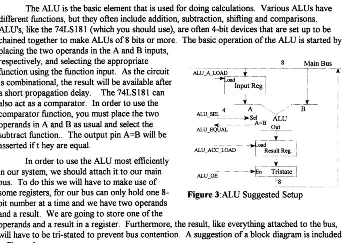
Topics: AID, D/A, ALUs, SRAM
Object: Design of Paddle I/O Velocity Counters
Design of Sound Unit (Optional)
Description: This lab has the students building much of the peripheral hardware that will be necessary for NetPong to function properly. Microcode will be written for the MCU to test the various components and make sure that they work properly.
Lab 6:
Topics: Message Queue Implementation
Summary of Messages and Necessary Processing Memory Storage Suggestions
Object: Create Stack in SRAM Write Game Microcode
Description: This final lab is mostly microcoding of the NetPong game and pulling all of the individual components together. The only hardware modification that the students may be working on is a modification to the SRAM to allow for hardware stack pointers. The students have the option of using a software stack pointer instead.
5.4 Documentation
The actual text of the labs and associated handouts is included in chapter 7. Lab Manual and Materials.
6. Lab Manuals and Materials
The lab manuals and associated material are included on the following pages. The following is a list of the various materials:
6.1 Overview
6.2 Prelab 1 & Lab 1 6.3 Prelab 2 & Lab 2 6.4 Prelab 3 & Lab 3 6.5 Prelab 4 & Lab 4 6.6 Prelab 5 & Lab 5 6.7 Prelab 6 & Lab 6
NetPong Overview
Statement of Purpose:
The purpose of this lab manual is to teach the principles of digital design. In this manual we will, through the course of six labs, develop a complicated digital system. Along the way, we will discuss such issues as digital control, storage and interaction between digital systems. The
most important concept that this manual will try to convey is the approach one takes to design. After a close look at the topic of digital design, it becomes apparent that there is very little previous knowledge necessary before delving into digital design. With this in mind, the lab was designed for audiences ranging from more advanced Juniors and Seniors in high school, to
College level students. In order to accomplish this, there are a number of optional extras that can be added to the lab sequence to tailor the difficulty. Furthermore, in a more advanced class, this lab sequence might be followed by student projects, either by groups or individually, which will be created from scratch.
The Goal:
When choosing the final goal of this lab sequence there were many important criteria to consider. First of all it, it had to be complicated enough to maintain the student's interest. Secondly, it had to incorporate all of the main digital systems concepts: control -Finite State Machines(FSMs), and Micro Control Units(MCUs), input/output -Digital to Analog (D/A) and Analog to Digital (A/D) converters, and basic building blocks -Programmable Array Logic (PALs), Static Random Access Memory (SRAM), Universal Asynchronous Receive Transmit (UARTs), and Programmable Read Only Memory (PROMs). Furthermore, the designers wanted to make sure that the project was interesting and that the students' hardware interacted with each other. After much thought about the issues, the designers came up with the concept of NetPong. NetPong will be a four player pong game where each student controls one side of the screen. The students' projects will be connected by a very rudimentary network which they will create.
What is Needed:
In order to complete these labs there is some equipment that is necessary. First and foremost, it is necessary to have an IBM compatible computer with a serial port and a VGA display. The software does not require a fast computer, and a fast 80286 should be sufficient (although this has not been tested).
In addition to the software specifically designed for the course, there are few other general purpose software packages that, while not required, will significantly simplify some of the projects. They include:
PALASGN: This software converts more intuitive equation files (*.eqn) into pal programming format (*.pal).
FSMC: This program stands for Finite State Machine Compiler. This program takes a description of a Finite State Machine (*.fsm) and produces an equation file compatible with PALASGN (*.eqn).
ASSEM: This program is used to compile microcode. It takes a microcode specification file (*.sp) and a microcode file (*.asm) and produces output file suitable for PROM programming(*.dat).
These three pieces of software are publicly distributed by MIT. The source code can be obtained by anonymous FTP from SUNPAL2.MIT.EDU. These software packages were designed for UNIX, but they were written in C and should be fairly easy to port to any major platform.
Further tools needed are a basic logic analyzer and an oscilloscope. They do not need to be high speed devices, as the suggested clock speed for the system is merely 153.6 KHz. This clock speed should allow the use of older and/or less expensive equipment. Furthermore, the course requires the use of some sort of PAL and PROM programmer.
It is assumed that the students will be building their projects on proto-boards. few suggestions that will make their work easier. First, before the students start their they should be provided with, or told how to, design the
following basic elements: Vcc
....
At least four (4) de-bounced switches.
At least four (4) LEDs that can be driven by TTL. These are suggested minimums that should be followed, more are always desirable. Furthermore, it would be helpful if the students had one or two hex displays with hex decoders, for easy monitoring of data.
There are a design,
470K0 0 .74LS14
Out
T7.4 gF
Figure 1: Suggested Switch Debouncer
Conventions:
To facilitate ease of use, the lab manual is laid out in a consistent format. The sections and a brief description of what they contain is listed below:
Prelab: Each prelab is separate from its associated lab which is intended to be handed out before the lab itself The prelabs present one or more significant design decisions to the students. The students are then required to analyze the situations and then suggest and defend a solution to the problem. The design questions to which the students are responding to are marked with the , symbol.
Object: This is the first section of every lab. It is simply a list of the relevant piece(s) of NetPong that will be built in the lab.
Topics: This is a list of the digital design concepts which are covered in the lab. Prelab Discussion: This section discusses the questions proposed in the prelab. If the
design decision affects other kits, then a suggestion is provided that is expected to be followed. If, however, the solution only affects the student's kit, they are free to implement any solution they feel is best. Because this section provides
answers to the Prelab, it is suggested that the labs be handed out after the prelabs so that the students have time to review the design problems and spend time understanding the issues.
Design Issues: This section provides information that is necessary to complete the lab at hand. Many digital design issues are discussed, but this is not intended to be a comprehensive source on all topics. It is intended to be an additional resource, for quick review or preview, that will compliment a digital design text and/or lecture.
Lab Assignment: The lab assignment section contains the actual lab assignments that the students are expected to complete. There are a few assignments that are for educational purposes only and are not strictly necessary for building NetPong. These assignments are marked accordingly.
Overall Design
The main emphasis of this lab manual is to teach design. Design is an iterative process. The process starts with the designer coming up with an exact description of the system to be created. All of the important criteria must be specified so that informed decisions can be made. After all of the criteria are available, the designer must brainstorm some possible overall
solutions. Keep in mind that just because one solution was found which satisfies the problem, this doesn't mean that there aren't additional solutions that are possibly simpler and cheaper to implement. These solutions don't have to incorporate every detail, they just have to define an overall approach to the problem. Solutions should include a high degree of modularity. This means designing sub-modules that are clearly defined and appear to be practical. The designer
should then make a list of the pros and cons of each design. The list should include complexity, ease of debugging (testability), costs, expendability, and any other criteria that is important to the designer. After the overall approach is decided, the designer should look at each of the sub-modules and again use the same design principles. After investigating the sub-sub-modules, you may feel that your overall approach may not have been the best one. Feel free to revise your previous decisions. You should realize that for every hour you spend designing you will likely save tenfold working on implementing and debugging your design. As the reader progresses through this lab manual, each stage of design will be demonstrated.
What you will be building
In order to design NetPong, we must fully understand what we want it to do. Most people should be familiar with the game of pong -the first video game. The object of the original game is to keep the ball on the playing field by hitting the ball with your paddle. You were only responsible for the bottom edge of the screen. In NetPong we will have a four player version of the game. Each player will control one edge of the screen. Each student or group of students will be responsible for designing their own player. In addition, a computer will be used to generate extra players (if there are less than 4 human players) and to generate the video portion of the game.
For the high level design of NetPong, we are going to use a simple single data bus architecture. This essentially means that there will a single data path on which information can travel which will connect a number of sub-modules. This architecture is chosen because it is the simplest to understand and implement. In high performance systems, a single bus system can cause problems due to the bottleneck that this design imposes. This shouldn't be a problem with this design because performance will most likely be limited by the speed of the network. As with any other design issue, if later on we notice that performance is an issue, we can revise the architecture.
In addition to an overall architecture, we need to come up with a list of the sub-modules. First and foremost, we need some idea of the functional elements that are required by our project. We will need some way to talk to the other kits to satisfy the "Net" in NetPong. We will also require some sort of storage unit to keep track of all of the game information. A calculation unit and a timing unit will be necessary to keep track of movement and a user I/O unit to provide input. Furthermore, we will need something to control the entire system and a system clock to keep everything synchronized.
Distilling those ideas we come up with a requirement for the following units: (1) Network Unit
(2) Storage Unit
(3) Arithmetic Logic Unit (ALU) (4) Timing Unit
(5) User I/O (6) Control Unit (7) System Clock
Each student (or group of students) will be building a game unit. These game units will be called 'kits' or 'players' throughout the lab. Each player will be responsible for receiving messages from the network that will be designed. The players will react to the messages by performing certain actions and/or sending other messages of their own. Messages that are to be
sent out are placed in a queue until the kit has permission to use the network. At this point, the queue will be emptied and all of the messages will be sent out. Using these basic elements we will design a multi-player game of pong.
NetPong Prelab #1
Network Topology:
Lets take a look at the Network Unit. This unit will be responsible for sending and receiving messages to the network that we are going to build. The first thing that we want to ask ourselves is, "What network?" We, of course, have to design that too. Often, when trying to solve a problem we learn that another problem will have to be solved first.
Requirements for the network:
Must allow 4 kits and 1 computer to communicate Must be easy to build
Must be reliable
Must be resilient to errors Due to their popularity and ease of use,
we are planning to use UARTs to form the
P'lay er" . - Playr3network. A UART is a device which takes a
byte and transmits it serially over a wire. It also ,(Hub
receives serial data and changes it back to a H .l.yer I Player 4.
byte. UARTs are used in computer serial ports.
This is all that you need to know about UARTs Computer Computer
at this time; more information will be necessary
when you actually need to use them. Star Network Ring Network
With a little thought, two basic network topologies emerge: a star topology and a ring topology. The star topology has the computer and the four kits plugged into a "hub". The responsibility of the hub is to give each port (the four players and the computer) a turn to talk. Each port then sends its messages to the hub, which redistributes it to all of the other ports. The ring topology, however, has each kit (player) and the computer plugged into both of their
neighbors (see diagram). Each kit takes incoming messages, processes them and passes them on. Unlike the star topology, the messages will continually go around the ring until removed.
Therefore it is the sending kit's responsibility to removing the messages.
A decision of this nature is crucial to our basic design and will have a very large impact on many decisions in the future. For this reason we should spend some time trying to weigh the advantages and disadvantages of these two designs.
C Your task in the prelab is to make a list of advantages and disadvantages of the two designs. Try to keep in mind all of the issues, including speed, ease of implementation (for both kits and computers), reliability, complexity, and any other issues you feel are important. After
making a list of the advantages and disadvantages, review the important design requirements of the project and make a choice as to which design would be best for our use. Insure that you defend your position.
Token Passing:
Let us form an analogy for our network: Consider all of the kits attached to our network as people in a room, and the hub is a policeman in the same room. The policeman (like our hub) is uninterested in speaking, but is interested in keeping order. Everyone has something that they want to say, but if they all talk at once no one can hear what anyone is saying. What we need to do is to create some type of system which will tell each person (i.e. kit) that it is their turn to talk. Now we are going to introduce the concept of a token, by giving the policeman a
microphone. The policeman gives the microphone to one of the speakers, who is the only person in the room who is allowed to speak. When that person is finished, they give the microphone back to the policeman. The policeman then gives the microphone to the next person, etc. Our network is like the room full of people because, if everyone talks at once, no one can hear what anyone is saying. We need to have a 'token' which, like the microphone, can be given to each kit when it is permitted to transmit data. When it is done transmitting, it returns the token to the hub. This analogy is describing a star based network, but all of the concepts are the same with the ring, except the people (and kits) pass the microphone (token) to the next speaker instead of to the policeman.
Another important design decision that has to be made about the network is whether we should be passing the token using a standard message or as a digital signal handshaking. If we were to pass the token as a standard message, we would do it by creating a message with an ID that said "pass the token". In addition, depending upon the topology chosen, it may or may not be important to say to whom you are passing the token. This, of course, depends upon whether you are sending messages to a single player (as in the ring topology), or broadcasting them to everyone (as in the star topology).
Token Provided Token Revoked
The digital signal handshaking is a method Token where a digital logic signal is raised when it is time
to pass the token to the next player. In order to do
this properly, two signal lines would be used to Token_Return
properly handshake between the two digital systems Retun TokenF.5
to insure that the signal is passed correctly. Figure 1:Digital Signal Handshaking
, Spend some time thinking about these two token passing methods. There are a number of important issues, such as ease of implementation, speed, and startup issues. If we are going to use a ring topology, which token passing system should we use? How about for the star topology?
NetPong Lab #1
Object:
Gain Familiarity with equipment Establish Appropriate Clocks
Design Network Hub Functional Logic
Topics:
Clocking Fanout Counters PALsPrelab Discussion:
Network Topology:In the prelab we introduced two potential methods for structuring our network. Some of the largest advantages and disadvantages of the two networks are listed below:
Star Network
Advantages:
Faster (at most 2 links per message, although it can be brought down to 1 link) Easier to hook up computer (only requires one serial port)
Central Arbitrator eases debugging. Disadvantages:
Requires additional hardware (the hub) Must change the hub to add more nodes
Ring Network
Advantages:
More scalable (any number of nodes can be added without changing hardware)
Disadvantages:
Slower (requires n links, where n is the number of nodes)
More difficult to hook up computer(uses 2
ports)
Kit Network Units must be more
complicated (know when to take message
off of the ring)
Looking at the list of advantages and disadvantages seems to show that for our
requirements (listed in the Prelab) the star network is preferable. It will be easier to hook up to a computer and, because of the central arbitrator, it will be easier to debug. Finally it is
considerably (five times) faster. It is not obvious that this is important at this stage of designing, but in general faster is always better for networks.
Token Passing:
Let us take a look at some of the important advantages and disadvantages of the two systems:
Message Passing Digital Signal Passing
Advantages: Advantages:
Easier to implement on a PC Faster
Easier to implement
Disadvantages: Easier Hub design
Slower
Difficult to start token Disadvantages:
More decoding logic Harder to design software
Looking at these two lists it appears that digital signal passing is probably the way to go. This holds true for both of the network topologies (Star and Ring). If we had to pass the token via message passing, it would certainly be easier on a Ring network, because each kit knows how to contact its neighbors, unlike the Star topology. As we have previously chosen to use the
Star topology, there is no question that we should use digital signal handshaking to pass the token.
Design Issues
FanoutAlthough we like to consider the logic gates purely as a digital abstraction, they are real electrical components which have some non-ideal properties, one of which is fanout. Each gate can supply or sink a limited amount of current. In addition, each input requires a little current to make them work properly. What this means in practice is that there is a limit to the number of gates that you can attach to an output. Fanout is defined as the number of gate inputs that can be driven by a single gate output. A typical TTL 74LS gate has a fanout of 20. If you attach too many gates to an output the quality of the signal will degrade and you will often get ringing in the signal, which can cause unpredictable results.
A crystal oscillator has a fanout of 1, so do NOT directly use the output of the crystal oscillator as your system clock. Instead, you should attach the crystal oscillator to an inverter and use the inverter output as the clock. For large circuits, even the output of one inverter may not be enough, so you can take the output
of the first inverter and use it to drive a
number of other inverters. The clock [
should be taken from the second row of L Clc
inverters (see diagram). Do NOT attach
Crystal
Clocks
the outputs of the second row of inverters I
together, instead have some devices
attached to each inverter. Figure 1: Suggested Clock Circuit for large attached to
each invertesystems