Design and experimental validation of a digital predictive controller for
variable-speed wind turbine systems
Article · January 2017 DOI: 10.6113/JPE.2017.17.1.232 CITATIONS 3 READS 339 4 authors, including:
Some of the authors of this publication are also working on these related projects: Industrial control systemsView project
power converterView project Badreddine Babes
Research Center In Industrial Technologies
23PUBLICATIONS 44CITATIONS
SEE PROFILE
Abdelmadjid Chaoui
Ferhat Abbas University of Setif
34PUBLICATIONS 292CITATIONS
SEE PROFILE
Hamouda Noureddine
Centre de recherche en technologie industriel CRTI-Algiers-Algeria
8PUBLICATIONS 17CITATIONS
SEE PROFILE
All content following this page was uploaded by Badreddine Babes on 16 February 2017.
232 Journal of Power Electronics, Vol. 17, No. 1, pp. 232-241, January 2017
https://doi.org/10.6113/JPE.2017.17.1.232 ISSN(Print): 1598-2092 / ISSN(Online): 2093-4718
JPE 17-1-23
Design and Experimental Validation of a Digital
Predictive Controller for Variable-Speed Wind
Turbine Systems
Badreddine Babes
†,
Lazhar Rahmani
*,
Abdelmadjid Chaoui
**,
and
Noureddine Hamouda
***†,*Automatic Laboratory of Sétif (LAS), Department of Electrical Engineering, University of Sétif 1, Algeria **Laboratory of Power Quality in Electrical Networks (QUERE), University of Sétif 1, Algeria ***Laboratory of Electrical Engineering of Constantine, University of Mentouri Brothers, Constantine, Algeria
Abstract
Advanced control algorithms must be used to make wind power generation truly cost effective and reliable. In this study, we develop a new and simple control scheme that employs model predictive control (MPC), which is used in permanent magnet synchronous generators and grid-connected inverters. The proposed control law is based on two points, namely, MPC-based torque–current control loop is used for the generator-side converter to reach the maximum power point of the wind turbine, and MPC-based direct power control loop is used for the grid-side converter to satisfy the grid code and help improve system stability. Moreover, a simple prediction scheme is developed for the direct-drive wind energy conversion system (WECS) to reduce the computation burden for real-time applications. A small-scale WECS laboratory prototype is built and evaluated to verify the validity of the developed control methods. Acceptable results are obtained from the real-time implementation of the proposed MPC methods for WECS.
Key words: Maximum power point tracking (MPPT), Model predictive control (MPC), Permanent magnet synchronous generator (PMSG), Wind energy conversion system (WECS)
I. I
NTRODUCTIONWind energy is considered one of the most promising non-conventional renewable energy sources (RESs) to address energy shortage, security threats, and environmental concerns. Among wind power generation systems, permanent magnet synchronous generators (PMSGs) are widely used in modern wind turbines [1] because of their variable-speed operation, fast dynamical response, high reliability, and efficiency. Power electronic converters and their control algorithms are involved in the operation of PMSGs to ensure
efficient control of wind turbines.
Converter topologies that vary in cost and complexity have been developed and studied for the power conditioning of PMSG-based wind turbine generator systems. The most commonly used topology is composed of a turbine rotor, a PMSG, an uncontrolled bridge rectifier, and a three-phase voltage-source inverter. The problem posed by the injection of rectified voltage into the network is its very low value. Connection via an isolation transformer is highly necessary to solve this problem. The inverter currents are high, so the losses of the inverter increase. The grid-connected transformer and grid filter become bulky because of these high inverter-side currents. A DC–DC boost converter is generally placed between the rectifier and inverter to obtain a small and highly efficient topology. Consequently, a high DC bus voltage is achieved, the network connection transformer presents a small ratio, and low inverter currents are obtained.
However, with this architecture, the controller design of the overall system becomes complicated for two reasons. First, the generator dynamics cannot be disregarded. As a © 2017 KIPE
Manuscript received Jul. 30, 2016; accepted Nov. 21, 2016 Recommended for publication by Editor in Chief Dong-Myung Lee.
†Corresponding Author: [email protected]
Tel: +213-7-356-6092, Fax: +213-6-955-9404, University of Sétif-1
*Automatic Laboratory of Sétif (LAS), Department of Electrical
Engineering, University of Sétif-1, Algeria
**Laboratory of Power Quality in Electrical Networks (QUERE),
University of Sétif-1, Algeria
***Laboratory of Electrical Engineering of Constantine, University of
result, system behavior is described by a highly coupled set of nonlinear differential equations. Second, the use of a simple generator and power electronic interface restricts the control authority. Several technical control approaches and algorithms have been developed for the control of the interfacing system between the PMSG wind turbine and power grid [2]. Examples include deadbeat control [3], adaptive control [4], feedback linearization control [5], and fuzzy logic control [6]. However, most of these schemes use output voltage and currents with outer and inner control loops and thus require proportional–integral (PI) regulators and sinusoidal pulse-width modulation that complicate the control system. Much tuning effort is also needed in practical implementation to ensure system stability. A control approach based on model predictive control (MPC) was proposed recently. There is no need for linear controllers or modulators, and the scheme is simple and easy to implement with standard commercial microprocessors. In this control approach, a discrete-time model of the system is employed to predict the behavior of the system variables for each possible switching state of the system, and the optimal switching states with minimum cost are selected and applied in the next sampling interval. The control objectives of MPC can vary considerably depending on the application. For example, in [7], the control objective is to ensure maximum power point tracking (MPPT) of the high-gain switched inductor quadratic boost converter output voltage for photovoltaic applications. In other applications, such as in [8], the objectives are related to controlling active and reactive power for a rectifier system. The currents for inverters in [9] were connected to an electrical machine or another electric load. Despite these systems, the MPC strategy for a renewable power generation system is seldom mentioned in literature.
The principal contribution of this study is the development and real-time implementation of a novel MPC strategy for a grid-connected wind energy conversion system (WECS). By changing the cost function correctly, this control strategy can be employed to ensure asymptotic convergence to the maximum power extraction point, regulation of rectified voltages to their desired values, and flexible power regulation of the electric grid. A new and simple prediction scheme is also developed to reduce the computation burden for real-time applications.
The remainder of this paper is organized as follows. Section 2 presents the system under consideration. Section 3 introduces wind turbine characteristics and maximum delivered power. Section 4 shows the modeling of PMSG. The control method developed for generators and grid-side converters is explained in Sections 5 and 6, respectively. Section 7 provides the simulation results and a comparison of these results with those of a wind turbine using the conventional PI controller. Section 8 presents the real-time validation of the different developed techniques and a
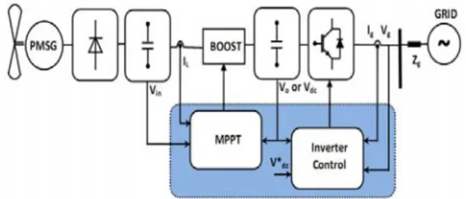
Fig. 1. Wind energy system under consideration.
scientific interpretation of the practical results. Section 9 shows a performance evaluation of the proposed controllers and the conclusions.
II. S
YSTEMD
ESCRIPTIONThe wind turbine employed in this study acts as a direct-drive system via a passive rectifier, a DC–DC boost converter, and a three-phase voltage inverter connected to the grid by a transformer to guarantee isolation. The torque resulting from the wind turbine reflected on the PMSG and the low voltage generated by the PMSG are rectified and amplified by the DC–DC boost converter and then transferred to the electric grid through a voltage-source transformer– inverter. The maximum power point controller controls the optimal speed of the generator to achieve maximum power of the wind turbine, and the finite-set model predictive direct power controller guarantees the smooth flow of power to the grid by maintaining a sufficient DC-link voltage.
During wind gusts, the dump load controller is activated to maintain the output load voltage at the desired value. A complete schematic of the system is provided in Fig. 1.
III. W
INDT
URBINEC
HARACTERISTICSThe output mechanical power for the wind turbine can be formulated as follows:
2 3
0.5
t p w
P
R C V
, (1) where R is the turbine radius (m), ρ is the air density (kg/m3), Vw is the wind speed (m/s), and Cp is the power coefficient of the turbine that is usually provided by the wind turbine manufacturer.The power conversion coefficient of a wind turbine (Cp) is influenced by the tip-speed ratio (TSR), which is calculated with m w
R
TSR
V
. (2) The curve (Cp-λ) characterizing the wind turbine is presented in Fig. 2. The power conversion coefficient and TSR are related to the aerodynamic characteristics of the wind turbine. Fig. 2 indicates that the maximum turbine power corresponds to λopt and Cp_max.234 Journal of Power Electronics, Vol. 17, No. 1, January 2017
Fig. 2. Power coefficient versus TSR.
The target optimum power from a wind turbine can be obtained as follows:
3 3 _ _0.5
_ max _ m optm opt p opt m opt
opt
R
P
AC
K
, (3) where A is the area swept by the turbine blade (A = π*R2),ωm_opt is an optimum rotation speed for a specific wind speed, and Kopt is an optimum wind constant provided by Equation (4). 3 _ _ max
0.5
m opt opt p optR
K
AC
(4) The target optimum torque can be provided by
2_ _
m opt opt m opt
T
K
. (5) Equation (4) can be used to realize MPPT control. The optimum rotational speed is calculated from the output power by controlling the wind turbine to operate at the optimum rotor speed. This condition guarantees that the maximum power is extracted from the incident wind.IV. M
ODELING OFPMSG
PMSG is modeled by its d–q equivalent circuits. The equations of a surface-mounted PMSG are expressed in synchronous d–q coordinates as ds ds s ds ds m qs qs di V R i L L i dt
, (6) qs qs s qs qs m ds ds mdi
V
R i
L
L i
dt
, (7)where Vds and Vqs are the stator voltages on the d and q axes, respectively; Lds and Lqs are the d and q components of generator inductance, respectively; ωm is the generator speed;
Ψ is the magnetic flux; and ids and iqs are the stator currents
on the d and q axes, respectively. The generator electromagnetic torque equation is
3
( )
2
e qs ds qs ds qs
T P
i L L i i . (8) Electromagnetic torque can be simplified and presented by Equation (9) if the two inductors are equal (Lds = Lqs).Fig. 3. PMSG control for MPPT.
3
2
e qs
T
P i
, (9) where P is the number of pole pairs.V. C
ONTROL OFS
WITCH-M
ODER
ECTIFIER WITHM
AXIMUMP
OWERE
XTRACTIONA. Proposed MPPT Control System
A block diagram of the developed control strategy for the switch-mode rectifier is depicted in Fig. 3.
Owing to the control of switch S, the maximum power of the variable-speed wind turbine is extracted, and energy is transferred to the grid inverter. The steps necessary for the control algorithm are as follows:
1- Wind speed Vw is measured.
2- The desired generator speed (ω* = ωm_opt) is calculated with the following equation:
_ opt m opt
K V
w w wR
. (10) 3- The error between reference and actual speeds is fed into the PI controller to set the reference torque generator (Tg_ref). The reference torque generator can be expressed as * _ i(
)
g ref p mK
T
K
S
, (11) where Kpω and Kiω are the proportional and integral gains for generator speed control. The reference torque (Tg_ref) participates to calculate the reference inductor current (iL*) by measuring rectifier output voltage Vin, as indicated in the following equation. _ * g ref m L inT
i
V
(12) 4- The iL* obtained from Equation (12), actual inductor current iL, and converter voltages Vin and Vo are defined as inputs of the numeric predictive technique to obtain considerable information in one sampling period and to generate control pulses for the insulated-gate bipolar transistor-based switch-mode rectifier operating the generator at optimum speed.Fig. 4. Two operating modes of the DC–DC boost converter circuit. (a) Open switch, S(t)=0. (b) Closed switch, S(t)=1.
B. Predictive Method Implementation
The principle of the MPC method is articulated on the use of the system model to be studied to predict the future behavior of variables control for each switching state. The action of the optimal control for this case depends on this information with a predetermined optimization criterion [10]. Fig. 4 illustrates a graphical analysis of the DC–DC boost converter. This converter involves only two switching states.
As shown in Fig. 4.a, when switch S is in off state (s(t)=0), the boost converter reacts as indicated by the following equation. 1 1 L o in di v v dt L L (13) When switch S is in on state (s(t)=1) as illustrated in Fig. 4(b), the first-order terms disappear and the former equation system is expressed as 1 L in di v dt L . (14) The discrete-time model of the DC–DC boost converter is used to derive Equations (13) and (14) in consideration of sampling period Ts. When the switch is turned off or on, the predicted control variables are given by Equations (15) and (16), respectively.
( 1) ( ) s ( ) ( ) L L in o T i k i k v k v k L (15) ( 1) ( ) s ( ) L L in T i k i k v k L (16) Prediction of the controlled variables iL can be realized in the next sampling interval (tk + 1) to obtain control schemes in the present and in the future simultaneously. The measured values of iL, Vin, and Vo are considered inputs for the predictive controller. The estimation of the future behavior of the controlled variables is performed on the basis of the evaluation of a cost function. Determination of cost function type is an important factor in the MPC algorithm because it represents the optimized difference between the controlled and desired values of the variables. In our studied case, the cost function is provided by*
(
1)
L L
J
i k
i
. (17) The cost function assures the tracking of inductor current iL from reference current iL* provided by the MPPT algorithm. In each sampling step, the cost function is evaluated twice forFig. 5. Finite-state MPC process.
Fig. 6. Flow chart of the model predictive controller.
each switching state. Evaluation of the cost function for different switching states determines the control actions for the next time instant. Fig. 5 illustrates the MPC process. The dotted line corresponds to the MPPT output, which defines the desired current. At sampling time tk, MPC must decide between S0 and S1 on the basis of having a minimized error thanks to the used cost function. The control actions taken by this technique are shown in black line while the other choices are inactive. All steps of the proposed MPC method are presented in Fig. 6.
VI. C
ONTROL OF THEG
RID-
SIDEC
ONVERTERA. Predictive Direct Power Control (DPC) Implementation
When the RESs are connected to the main power grid, flexible active and reactive power regulation must be achieved to support the stability of the power system. Therefore, the control objectives of MPC are studied to ensure good control of active and reactive power. Fig. 7 shows a schematic of the grid-side converter controller. The model-based predictive approach for this controller calculates the active and reactive power for the possible switching combinations.
The key procedure in this scheme is the prediction of power at the (k+1)th sampling instant for different voltage vectors. This assumes that an optimal voltage vector is able to minimize the power ripple effectively when applied during the interval between (k)th and (k+1)th instants [11]. Seven traditional inverter voltage vectors (V0…V7) are used to
236 Journal of Power Electronics, Vol. 17, No. 1, January 2017
Fig. 7. Basic principle of the proposed MPC–DPC strategy for power delivered to the grid.
control active and reactive power. Consequently, the mathematical modeling of the system in the stationary coordinates (α-β) can be described as [12]
g g
di
e
L
R i
V
dt
, (18)where Rg and Lg are the equivalent series resistance and inductance of the grid filter, respectively.
The instantaneous active and reactive power exchanged with the grid can be formulated as [13]
3 2 P e i e i , (19)
3 2 Q e i e i . (20)Instantaneous change in active and reactive power can be expressed as 3 2 de di de di dP i e i e dt dt dt dt dt , (21) 3 2 de di de di dQ i e i e dt dt dt dt dt . (22) Given that the main voltage is sinusoidal and balanced, the components can be provided by the expression
cos sin
j t
e e je e e e tj e t , (23)
where ω is the grid frequency in rad/s. The following equations are then obtained.
cos
sin d e t de e t dt dt (24)
sin
cos d e t de e t dt dt (25) For simplification, Equations (24) and (25) becomede e dt
, (26)de
e
dt
. (27) By substituting Equations (18), (26), and (27) into (21) and (22), the power variations can be obtained as
3 2 g g g e dP e i V e i R e i e V e i R dt L , (28)
3 2 g g g e dQ e i V e i R e i e V e i R dt L . (29) In consideration of Equations (19) and (20),
* , eV e V e V j e V e V ande
2e
2e
2,
Equations (28) and (29) can be rewritten as
* 2
3 Re 2 g g g R dP P Q e V e dt L L , (30)
* 3 Im 2 g g g R d Q P Q e V d t L L . (31) Both powers at the end of sampling time Ts can be predicted as
* 2
3 ( 1) ( ) ( ) Re ( ) 2 g s g g R P k T P k Q k eV e P k L L , (32)
* 3 ( 1) ( ) ( ) Im ( ) 2 g s g g R Q k T P k Q k eV Q k L L . (33) Based on a cost function, assessment of the application of each voltage vector is then performed and selected to obtain the minimum active power and reactive undulations. For this command, the cost function is formulated as follows:
*
2 *
2( 1) ( 1)
P
J P P k Q Q k , (34)
where P* and Q* are the reference active power and the reference reactive power, respectively.
B. One-step delay compensation in digital validation In the real-time implementation of the MPC method, there is usually one-step delay caused by the update mechanism in modern digital signal controllers [14]. To compensate the influence caused by the one-step delay, the value at the (k+2)th instant must be used instead of that at the (k+1)th instant. However, it can be seen that the power prediction using Equations (32) and (33) is complicated and leads to difficult implementation. A new and simple prediction scheme is developed to overcome this issue. The proposed method uses only one past value, as shown in Fig. 8.
The predicted active and reactive power, P(K+1) and
Q(k+1), can be simply extrapolated to the (k+2) state as
follows:
(
2) 2 (
1)
( )
P k
P k
P k
, (35)(
2) 2 (
1)
( )
Fig. 8. Predictive value estimation of active power.
Hence, the objective function in Equation (34) should be modified and presented in a new form as follows:
*
2 *
2( 2) ( 2)
P
J P P k Q Q k . (37)
VII. S
IMULATIONR
ESULTSANDD
ISCUSSIONA. Results Analysis
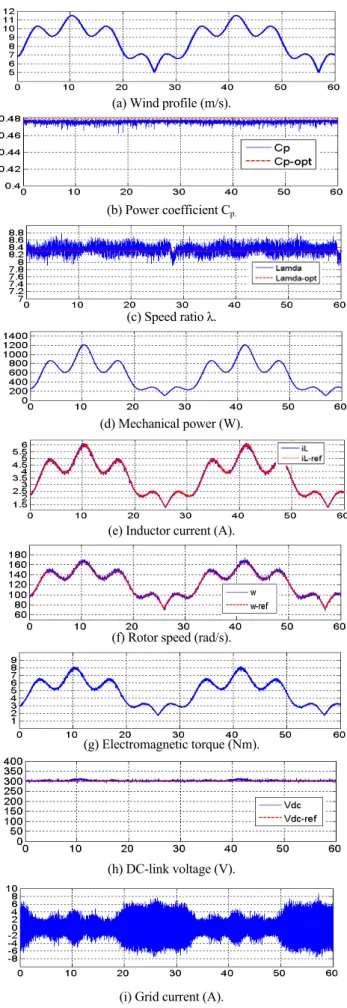
Simulations are conducted with MATLAB 7.1 software to confirm the effectiveness of the proposed predictive control strategy. The particular parameters of the system are given in the Appendix. The simulation of the wind speed profile corresponding to the used turbine is shown in Fig. 9(a).
Figs. 9(b) and 9(c) show that the power coefficient and speed ratio are adjusted to their references, which indicate that the captured power is maximal (Fig. 9(d)). Fig. 9(e) shows the control performance of the inductor current. As depicted, the control performance of the predictive controller is good under wind fluctuations. Fig. 9(f) shows a good following of the rotor speed to the reference speed which controlled by the generator torque shown in Fig. 9(g). Fig. 9(h) shows the DC-link voltage, which is kept constant at approximately 300V. It is observed that the grid-side current and voltage are almost sinusoidal that improve the performances of the grid-side converter (Figs. 9(i) and 9(j)); therefore, direct power predictive control is assured.
B. Comparison with the Traditional PI Controller This section compares the simulation results of the PMSG wind turbine using the proposed predictive control scheme with that of the same wind turbine using the traditional PI controller. The wind speed profile shown in Fig. 10(a) is used to test the proposed predictive control strategy and conventional PI controller.
We compare power coefficient Cp in Fig. 10(b). Fig. 10(b) depicts that with the proposed predictive control scheme, Cp only varies in a narrow range, 0.40 < Cp < 0.48. By contrast, with the traditional PI controller, Cp varies in a wide range.
As shown in Fig. 10(c), the optimum generator power-tracking error can be maintained within 5% by using the proposed control strategy, whereas this tracking error commonly exceeds 15% when the conventional PI controller is used, and thus is completely unacceptable. Generally because the power coefficient Cp, with the conventional PI
(a) Wind profile (m/s).
(b) Power coefficient Cp.
(c) Speed ratio λ.
(d) Mechanical power (W).
(e) Inductor current (A).
(f) Rotor speed (rad/s).
(g) Electromagnetic torque (Nm).
(h) DC-link voltage (V).
238 Journal of Power Electronics, Vol. 17, No. 1, January 2017
(j) Grid current (A) and grid voltage (V).
Fig. 9. Simulation results of the system for wind speed variation.
(a) Wind profile (m/s).
(b) Power coefficient Cp.
(c) Mechanical power (W).
(d) Rotor speed (rpm).
(e) Total energy (J).
Fig. 10. Comparison of the proposed predictive control method and traditional PI control method.
controller, is reduced significantly during sudden variations in wind speed.
These comparative simulation results demonstrate that the proposed control strategy is superior to the conventional PI control method in terms of optimum generator power-tracking control and maximum power extraction.
As shown in Fig. 10(d), rotor speed can be accurately controlled to adapt to the wind speed variations, and the speed-tracking error can be kept within 5% by using
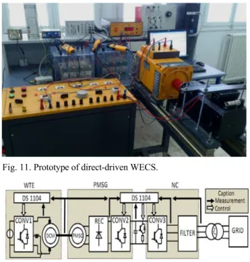
Fig. 11. Prototype of direct-driven WECS.
Fig. 12. Schematic of the experimental platform.
the proposed control strategy. On the contrary, the speed-tracking error exceeds 10% when the conventional PI controller is used. Thus, the proposed control strategy achieves better optimum rotor speed-tracking control than the conventional PI controller.
Fig. 10(e) indicates that a higher mechanical energy part is stored in its mechanical system to accelerate the rotor speed by the proposed predictive controller than that by the traditional PI controller. This result affirms the improved efficiency of the proposed predictive control method.
VIII.
E
XPERIMENTALR
ESULTSANDD
ISCUSSIONA. Hardware Implementation
An experimental platform of WECS is developed in the laboratory, as shown in Fig. 11, to verify the performance of the developed predictive control technique. The necessary parameters used for this practical validation are presented in the Appendix. The first motor is a DC machine controlled in torque-producing mode, in which the torque reference changes along with the rotor speed. A preset table is created between the reference torque and speed depending on the power characteristic of the wind turbine, in which the mechanical torque is changed by wind velocity and generator speed.
Fig. 12 shows the global schema of the studied system connected to the grid, examined, and evaluated in real time when the generator speeds up and the speed of the PMSG is governed by the control device of the network-side converter. The real-time implementation of the developed techniques requires dSPACE 1104 cards and a complex programmable
logic device. dSPACE must guarantee the three main tasks, namely, (i) provide the torque reference from the wind turbine emulator, (ii) extract and exploit the maximum power from the wind (iii), and feed the grid with good-quality of electric energy. Controller performance is evaluated in both the generator-side switch-mode DC–DC converter and the grid-side voltage-source inverter. The obtained results are presented in dynamic conditions for the variations in wind speed and steady state for reference real and reactive powers. B. Test Results under Transient State
Figs. 13(a) to 13(j) show several experimental results presented using the Control Desk software. Wind speed is shown in Fig. 13(a). Fig. 13(b) shows that the speed of the PMSG can track the tendency of the optimal reference speed very well, and regulate the turbine torque to extract maximum power from the wind turbine. The Cp is usually near to the optimal value of Cp_max= 0.48 despite the high rotational turbulence, as shown in Fig. 13(c). Fig. 13(d) presents the control performance of the inductor current. As depicted, the control performance of the predictive current controller is good under wind variations. Fig. 13(e) shows the change in electromagnetic torque, we can remark that its value increases as the wind speed increases. The turbine mechanical input power is illustrated in Fig. 13(f). Typically, the mechanical power is oscillated due to wind speed variations. The DC-link voltage is controlled at its reference with good precision during the wind variations, as shown in Fig. 13(g). The grid current controlled by the proposed method is displayed in Fig. 13(h). The grid current can reach the steady state within one cycle, which illustrates that the proposed method has good dynamic performance. The grid current is in phase with the main voltage, as depicted in Fig. 13(i).
Fig. 13(j) indicates that good tracking performances are achieved in terms of grid active and reactive power with respect to wind speed variations. The grid reactive power is maintained at zero value, contributing to compensate the grid power. The obtained results confirm that the proposed predictive technique functions correctly and exhibits very good dynamic performance.
C. Test Results under Steady-State Condition
The characteristic waveforms of the grid-interfaced WECS under steady-state condition, where the wind speed is assumed to be constant, are shown in Figs. 14(a) to 14(d). It is clearly seen from Fig. 14(a) that the total harmonic distortion (THDi) of the injected current is less than 5% in the entire three-phase limit imposed by the IEEE-519 norm. Fig. 14(b) shows the measured results of the power factor (PF) of WECS. It is obvious that the power factor is very close to the unity where it presents a value of 0.974, is close to unity and can satisfy the PF demand in industrial applications. Fig. 14(c) illustrates the three-phase injected currents of
(a) (b) (c) (d) (e) (f) (g) (h) Cp_opt Cp vdc-ref vdc Il_ref IL ωref ω
240 Journal of Power Electronics, Vol. 17, No. 1, January 2017
(i)
(j)
Fig. 13. Experimental results of the system for wind speed variation.
Fig. 14. Experimental steady-state waveforms of the proposed predictive DPC method.
Fig. 15. Experimental waveforms of the proposed predictive DPC.
sinusoidal waveforms. Also, it can be clearly remarked that the three-phase currents are symmetric and strictly follow their corresponding phase voltages. The DC link is maintained close to its references (Vdc_ref = 300V) with good
precision and stability. The injectedcurrent is in phase with the main voltage, as depicted in Fig. 14(d).
The experimental results in steady state are illustrated in Figs. 15(a) to 15(c). It is clearly seen in this representation that the grid voltage and current for the two cases of the system function. The first operationoperating with a unity power factor (Fig. 15(a)) and the second one with a leading and lagging PF (Figs. 15(a) and 15(b)) are in phase for the first case and phase shifted for the second case. In addition, reactive power reacts correctly in both tests. In order to test and evaluate the ability of the proposed WECS to control the reactive power that is governed for unity, leading, and lagging PF functions at the grid side is tested and evaluated with the conservation of active power constant, as presented in Fig. 15(d).
IX. C
ONCLUSIONSA simple and intuitive approach that uses the predictive control strategy was developed for a grid-connected PMSG-based WECS. For full use of wind energy, the developed control method ensures the decoupling of active and reactive power for the grid-side converter and guarantees maximum power-tracking control for the generator-side inverter. The wind turbine requirements, such as MPPT and active and reactive power generation, are modeled as the reference control variables. The generator- and grid-side cost functions are defined to deal with these control objectives. During each sampling interval, the control goals are achieved based on minimization of cost functions. The efficiency of the system has been evaluated through simulation and experimental tests. The results showed fast, accurate, and effective responses in dynamic and steady-state operating conditions.
A
PPENDIX TABLEISPECIFICATION OF THE WIND TURBINE
Parameter Value Units
Wind turbine blade length (R) Air density ()
Optimal tip speed ratio (opt)
Maximum power coefficient (Cp opt)
1.02 1.225 8.08 0.48 m kg/m3 - - TABLEII PMSGPARAMETERS
Parameter Value Units
Rated output power of PMSG (PN)
Rated torque (TN)
PMSG stator resistance (Rs )
PMSG stator inductance (Ls)
Permanent magnet flux () Pole pairs (P) Torque constant (kT) 5 22.5 0.65 8 0.39 4 2.39 KW Nm mH Wb - Nm/A ig vg Active power Reactive power Q*(k+1) Q(k+1) P*(k+1) P(k+1)
R
EFERENCES[1] A. Beddar, H. Bouzekri, B. Babes, and H. Afghoul, “Experimental enhancement of fuzzy fractional order PI+I controller of grid connected variable speed wind energy conversion system,” Energy Conversion and Management, Vol. 123, pp.569-580, Sep. 2016.
[2] R. Melício, V. M. F. Mendes, and J. P. S. Catalão, “Power converter topologies for wind energy conversion systems: integrated modelling, control strategy and performance simulation,” Renewable Energy, Vol. 35, No. 10, pp. 2165- 2174, Oct. 2010.
[3] L. Tong, X. Zou, S. S. Feng, Y. Chen, Y. Kang, Q. Huang, and Y. Huang, “An SRF-PLL-based sensorless vector control using the predictive deadbeat algorithm for the direct driven permanent magnet synchronous generator,”
IEEE Trans Power Electron., Vol. 29, No. 6, pp. 2837-
2849, Jun. 2014.
[4] E. Giraldo and A. Garces, “An adaptive control strategy for a wind energy conversion system based on PWM-CSC and PMSG,” IEEE Trans. Power Syst., Vol. 29, No. 3, pp. 1446-1453, May 2014.
[5] F. Delfino, F. Pampararo, R. Procopio, and M. Rossi, “A feedback linearization control scheme for the integration of wind energy conversion systems into distribution grids,”
IEEE Syst. J., Vol. 6, No. 1, pp.85-93, Mar. 2012.
[6] N. A. Gounden, S. A. Peter, H. Nallandula, and S. Krithiga, “Fuzzy logic controller with MPPT using line-commutated inverter for three-phase grid-connected photovoltaic systems,” Renewable Energy, Vol. 34, No. 3, pp. 909-915, Mar. 2009.
[7] O. Abdel-Rahim, H. Funato, and J. Haruna, “Novel predictive maximum power point tracking techniques for photovoltaic applications,” Journal of Power Electronics, Vol. 16, No.1, pp. 277-286, Jan. 2016.
[8] S. Kwak, U.-C. Moon, and J.-C. Park, “Predictive control based direct power control with an adaptive parameter identification technique for improved AFE performance,”
IEEE Trans Power Electron., Vol. 29, No. 11, pp. 6178-
6187, Nov. 2014.
[9] Y. Zhang and W. Xie, “Low complexity model predictive control single vector based approach,” IEEE Trans Power
Electron., Vol. 29, No. 10, pp. 5532-5541, Oct. 2014.
[10] S. Kouro, P. Cortes, R. Vargas, U. Ammann, and J. Rodriguez, “Model predictive control simple and powerful method to control power converters,” IEEE Trans
Ind. Electron., Vol. 56, No. 6, pp. 1826-1838, Jun. 2009.
[11] P. Antoniewicz and M. P. Kazmierkowski, “Virtual flux based predictive direct power control of AC/DC converters with online inductance estimation,” IEEE Trans. Ind.
Electron., Vol. 55, No. 12, pp. 4381-4390, Dec. 2008.
[12] S. Yang, Q. Lei, F. Z. Peng, and Z. Qian, “A robust control scheme for grid connected voltage source inverters,” IEEE
Trans. Ind. Electron., Vol. 58, No. 1, pp. 202-212, Jan.
2011.
[13] Z. Song, W. Chen, and C. Xia, “Predictive direct power control for three phase grid connected converters without sector information and voltage vector selection,” IEEE
Trans. Power Electron., Vol. 29, No. 10, pp. 5518-5531,
Oct. 2014.
[14] P. Cortes, J. Rodriguez, C. Silva, and A. Flores, “Delay compensation in model predictive current control of a three phase inverter,” IEEE Trans. Ind. Electron., Vol. 59, No. 2, pp. 1323-1325, Feb. 2012.
Badreddine Babes was born in El Eulma,
Algeria, in 1980. He received his degree in electrical engineering from Ferhat Abbas University, Sétif, Algeria, in 2004. He started working in the industry for three years after that. He received his MS degree from Ferhat Abbas University in 2010. He is currently working for his Ph.D. degree in electrical engineering at the same university. His specific research interests are in the areas of predictive control of linear and nonlinear systems applied to motor drives and renewable energy systems.
Lazhar Rahmani was born in Algeria in
1964. He received his degree in electrical engineering from University of Annaba in 1991 and his D.E.A. and Ph.D. degrees in electrical engineering from University of Setif, Algeria, in 1994 and 2005, respectively. He is currently an assistant professor at the Department of Electrical Engineering, University of Setif. His current research interests include modeling and advanced control of power converters and power electronic systems and their digital control techniques. These topics deal with power quality such as active filters.
Abdelmadjid Chaoui was born in Sétif. He
received his engineering and magister degrees in electrical engineering from Sétif University, Algeria, in 1990 and 1996, respectively. In 2010, he obtained his Ph.D. in power electronics and control from Sétif University, Algeria, and Poitiers University, France. He is currently an assistant professor at the Department of Electrical Engineering, University of Sétif-1, Algeria. He is a member of the Laboratory of Power Quality in Electrical Network, Sétif-1 University. His main research interests are power electronics control applied to renewable energy and power quality systems.
Noureddine Hamouda was born in Jijel,
Algeria, in 1981. He received his electrical engineering degree from University of Jijel, Algeria, in 2006. He received his MS degree from University of Setif-1 in 2010. He is currently working for his Ph.D. degree in electrical engineering at University of Constantine. Since 2013, he has been with the Research Center in Industrial Technologies, Algiers, Algeria. His specific research interests are systems applied to motor drives, renewable energy systems, and improvement of power quality systems. He is also currently interested in welding techniques.
View publication stats View publication stats