Design and In vitro Development of Resorbable
Urologic Drug Delivery Device
by
Irene S. Tobias
S.B. Materials Science and Engineering Massachusetts Institute of Technology, 2007
SUBMITTED TO THE DEPARTMENT OF BIOLOGICAL ENGINEERING IN PARTIAL FULLFILLMENT OF THE REQUIREMENTS FOR THE DEGREE OF
MASTER OF ENGINEERING IN BIOLOGICAL ENGINEERING AT THE
MASSACHUSETTS INSTITUTE OF TECHNOLOGY
fJure
.2oo?]
MAY 2008
©2008 Massachusetts Institute of Technology. All rights reserved
Signature of Author:
-Irene S. Tobias Department of Biological Engineering
/7
May 23, 2008
Certified by:
Michael J. Cima Professor of Materials Science and Engineering, MIT Thesis Supervisor
CA
Certified and Accepted by:
.ASACHI-'rr ws-mTE I-.- // • OF TECHNOLOGY
JUL 2 8 2008
LIBRARIES
Darrell J. Irvine Associate Professor of Materials Science and Biological Engineering, MIT Thesis Reader Co-Chair, Master of Engineering in Biomedical Engineering Program 1Design and In vitro Development of Resorbable
Urologic Drug Delivery Device
by
Irene S. Tobias
Submitted to the Department of Biological Engineering On May 23, 2008 in Partial Fulfillment of the Requirements for the
Degree of Master of Engineering in Biological Engineering
Abstract
Implantable, controlled release drug delivery devices offer several advantages over systemic oral administration routes and immediate drug release treatments including direct therapy to target organ, more continuous maintenance of plasma and tissue drug levels and the potential for reduced side effects or toxicity. Urology has emerged as a unique field in which minimally invasive implantation techniques are available and such devices could provide improved beneficial therapies over conventional treatments. Urological indications for which localized drug therapy is already being advocated and investigated are highly suitable for treatment with implantable controlled release devices. This thesis describes the in vitro
performance evaluation of an implantable, bio-resorbable device that can provide localized drug therapy of ciprofloxacin (CIP) to the seminal vesicle and nearby prostate gland for treatment of chronic prostatitis (CP). The device functions as an elementary osmotic pump (EOP) to release CIP for a period of 2-3 weeks after implantation in the seminal vesicle (SV) through transrectal needle injection or cystoscopic methods. The device is composed of an elastomeric, resorbable polymer cast in a tubular geometry with solid drug powder packed into its core and a micro-machined release orifice drilled through its wall. Drug release experiments were performed to determine the effective release rate from a single orifice and the range of orifice size in which osmotic-controlled zero-order release was the dominant mechanism of drug delivery from the device. Device stability and function in an alkaline environment of similar pH to that of the SVs and infected prostate gland was also assessed in vitro. The device was found to function well in both de-ionized water and NaOH pH-8 solution with a sustained zero-order release rate of 2.47 ± 0.29 jtg/hr when fabricated with an orifice of diameter 100-150pm.
Thesis Supervisor: Michael J. Cima, Ph.D.
Table of Contents
Abstract 3
List of Figures and Tables 6
1.0 Introduction 7
1.1 Chronic Prostatitis 7
1.2 The Seminal Vesicle 9
1.3 Device Concept, Components and Design 12
1.3.1 Osmotic Pump Devices 12
1.3.2 Material Selection: Poly(glycerol-sebacic acid) 17
1.3.3 Drug Selection: Ciprofloxacin 20
1.3.4 Proposed Implantation Route 24
2.0 Device Engineering 26
2.1 Casting of PGS Modules 26
2.2 Fabricating Release Orifices 29
2.3 Drug Rod Casting 30
3.0 Materials and Methods 33
3.1 PGS/PLGA degradation experiments 33
3.2 CIP HPLC method and stability testing 34
4.0 Results 38
4.1 PGS/PLGA Degradation Experiments 38
4.2 Summary of CIP HPLC method and stability testing 40
4.3 CIP Release Experiments 41
5.0 Discussion 48
5.1 PGS/PLGA Degradation Experiments 48
5.2 CIP Release Experiments 49
6.0 Conclusions 52
7.0 Future Work 53
8.0 Acknowledgements 56
List of Figures and Tables
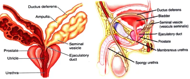
Fig. 1 : Illustration of the seminal vesicles 10
Fig. 2: Cross-sectional slices of the seminal vesicle. 10
Fig. 3: Illustration of device operation. 15
Fig. 4: PGS synthesis reaction. 19
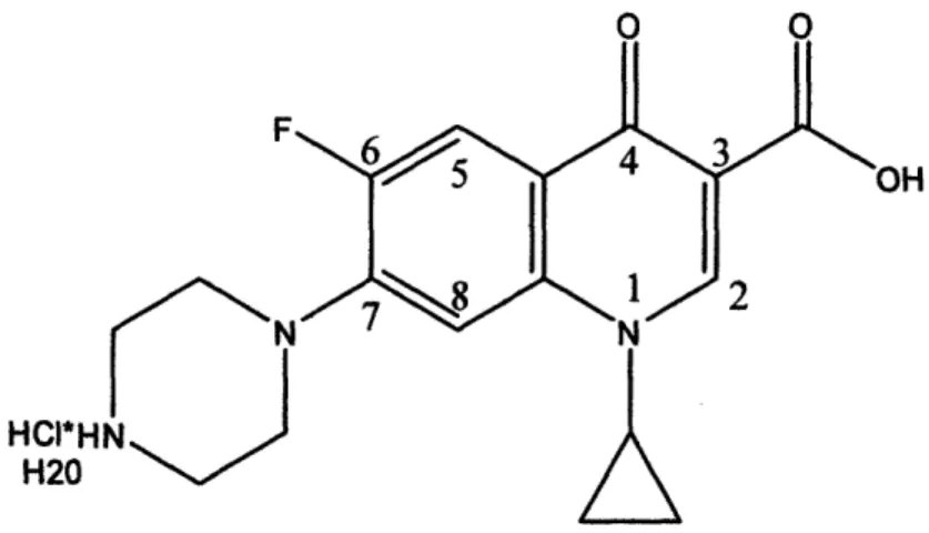
Fig. 5: Chemical structure of Ciprofloxacin-HC1. 22
Fig. 6: Photographs of aluminum PGS molds. 27
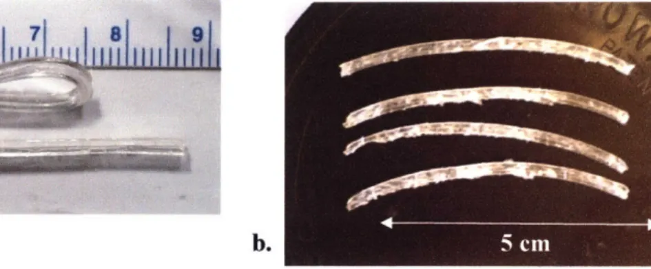
Fig. 7: Tubular modules cut from PGS castings. 28
Fig.8: Photograph of right angle corner mount with paper template 30
Fig. 9: CIP drug rod casting process 32
Fig. 10: Schematic illustration of mold used to cast PGS. 36
Fig. 11: Schematic drawing of CIP-loaded PGS release modules 37
Fig. 12: Mass loss of PGS and PLGA from in vitro hydrolytic degradation 38
Fig. 13: HPLC chromatogram showing CIP retention time around 5.6 minutes 41 Fig. 14: Photographs of PGS modules containing packed CIP rods. 41 Fig. 15: CIP release profiles from PGS modules with different sized orifices. 42 Fig. 16: Release rate*(average PGS wall thickness) vs. time after induction 43
Fig. 17: High pH inhibition of drug release from device 47
Fig. 18: Illustration of male rabbit genitourinary anatomy. 54
Table 1: Summary of linear fitting for PGS mass loss data... ... 39
1.0
Introduction
The aim of the work surrounding this thesis is to use newly developed material
technologies and established drug release mechanisms to build drug delivery devices for
urological indications. This thesis focuses more specifically on the development of a device that
can provide localized drug therapy to the seminal vesicle and nearby prostate gland for treatment
of chronic prostatitis (CP). The approach is to fabricate passive resorbable release devices that
can be injected through a trans-rectal needle or implanted via cystoscopic techniques and deployed into the seminal vesicle for a treatment period of 2-3 weeks. The soluble drugs used for this application will be stored in solid form within the device to maximize drug payload and minimize device size. Release of the drug will be controlled by a combination of micro machined orifices and the water permeability of the material used to construct the device body. This fully resorbable device will be fabricated from a novel elastomeric material that has been tested for biocompatibility but has not yet been used for urological purposes.1.1 Chronic Prostatitis
Prostatitis (an inflammatory condition of the prostate gland) presents with symptoms that often include chronic pelvic pain, urinary dysfunction in the form of frequency, urgency or weak stream, pain on urination, and sexual dysfunction.1'2 The condition is estimated to have a
prevalence of 10% in men and to cause symptoms in half the male population at some point in their lifetime.3 Prostatitis can either occur as an acute infection of the prostate gland (acute bacterial prostatitis) or more commonly as a recurring condition (chronic prostatitis). The chronic category is further subdivided into bacterial (CBP) and abacterial (ACP) depending on the ability to isolate a suspected causative pathogen from the prostatic fluid or urine."2 Chronic
prostatitis causes a comparable degree of impairment to the patient's quality of life as that caused
by coronary artery disease or Crohn's disease.
1The most common pathogen isolated in CBP is Escherichia Coli, accounting for about 80%
of all CBP cases
2, yet CBP accounts for only 5-15% of all chronic prostatitis cases.1,
4Bacteria
are still thought to cause a significant percentage of CP cases, hence antimicrobial agents are
commonly prescribed.' The rationale behind this treatment strategy is that the failure to isolate
a suspected pathogen does not necessarily rule out its presence, as current culture techniques are
not entirely accurate.
2The prescription of antibiotics for culture-negative prostatitis (ACP) is
further supported by clinical evidence showing positive response of ACP cases to treatment with
antibiotics.
5'
6Several investigators have recommended that all patients presenting with chronic
prostatitis (both CBP and ACP) should be treated initially with antibiotics for 2 weeks and
receive continued treatment if symptoms improve.
2The choice of antibiotics is critical, as- the prostate and nearby seminal vesicles present a
significant pH gradient. The chosen antibiotic must have sufficient chemical stability over a
wide range of pH while also exhibiting effective penetration into the prostate gland. The
zwitterionic fluoroquinolones such as ciprofloxacin (CIP) and levofloxacin have surpassed older
drug treatments for CP such as trimethoprin-sulfamethoxazole (TMP-SMZ) in both effective
bacterial eradication and cost-effectiveness.' 500 mg of CIP administered twice a day for 28
days yielded bacteriological cure rates of 63-76% in clinical studies
7'
8'
9whereas most studies on
TMP-SMZ or TMP alone yielded efficacy rates between 30-50 % and required longer duration
of therapy (90 days).'
Several investigators have advocated for direct injection of antibiotics to the prostate gland
due to the relatively high failure rate of systemic antibiotic administration.10',11,12,13 The failure oforal antibiotics is thought mainly to be due to an associated local autoimmune disease process and the possible presence of intraprostatic bacterial biofilms which resist drug penetration, providing a therapeutic argument for local antibiotic administration.'3 Guercini et al. have also
demonstrated enhanced improvement in therapy with additional co-administration of betamethasone , an immuno-suppressing steroid infused in a cocktail solution with antibiotics to the prostate in order to counter the effects of the autoimmune disease process. CP patients who had experienced repeated failure of oral antibiotics in the previous 12 months underwent prostatic infiltration of antibiotics and betamethasone in this study. 68% of the study participants were effectively cured and 13% showed no response.'3 Local prostate antibiotic injection has
generated advocacy and shown reasonable efficacy in clinical trials, yet it has not yet become a popular or widespread therapy in use among most urologists.' A fully resorbable drug delivery
device residing in the seminal vesicle may replace multiple intraprostatic injections as a sustained treatment of antibiotics over an extended period of time while maintaining the benefits of local therapy.
1.2 The Seminal Vesicle
The seminal vesicles (SVs) are a pair of coiled tubular glands which form lateral outpouchings of the ampulla of the vas deferens (Fig. 1), the tortuous duct which connects the epididymis of the testes to the prostate gland.14 They are normally 5-10 cm in length and 3-5 cm in diameter in the adult human male, with an average volumetric capacity of 13 ml and fluid capacity of 3-4 ml.14,15 They are each comprised of a single coiled tubule about 15 cm long and
2-6 mm in diameter.16' 17 The pouches surrounding the lumen of the SV tubule are lined by
distended without injury when the tubule fills with fluid (Fig. 2).14,16 The tubule is encased in a thin layer of smooth muscle which contracts during ejaculation to release fluid and is held in a coiled configuration by loose adventitia. The SVs and the ampulla form the ejaculatory duct which empties into the prostate gland and are located posterior to the bladder, separated from the
rectum by Denonvilliers' fascia (Fig. 1).14
I
-Ductus deferens .. Bladder ,-Seminal vesicle (vesicula seminalis) Ejaculatory duct -Prostate Membranous urethra ra UrethraFig. 1 : Illustration of the seminal vesicles, prostate gland and other organs of the male genitourary tract.'8
Fig. 2: Cross-sectional slices of the seminal vesicle.
Left: mucosal folds are lined with secretory epithelium and goblet cells." Right: Smooth muscle walls encase the pouches of the gland.2 0
The SVs secrete fluid which supplies nearly 50-80% of the total ejaculate volume. Important components of these secretions include fructose which contributes to sperm motility as well as prostaglandins and a coagulation factor.15 These secretions are alkaline (pH of 7.8 in vesicular lumen)21 which combine with slightly alkaline secretions from the prostate gland (pH
of 7.3)22 to produce semen with a normal pH range of 7.2 to 8.0.23
Cancer originating in the SVs is rare, although secondary invasion of tumors from the nearby prostate gland, bladder, or rectum is much more common. The extremely low proliferative activity of the seminal vesicle epithelium has been suggested as a reason for the suppression of cancer development within these glands.'5 Infection and inflammation of the SVs (vesiculitis) is also uncommon in the US and is usually treated with systemic antibiotics. The proposed device could be used to treat cases of vesiculitis in addition to the more common condition of prostatitis.
Implantation of the SVs has been performed in both animals and humans. Copper and silicone implants in the forms of wires and tubes have been implanted within the vesicular lumen of hamsters, rabbits and rats for fertility studies.24,2 5 Both implant types precipitated frequent
coagulation of the SV secretions within the rat and significantly reduced rat fertility but did not cause coagulation or markedly decrease fertility in the rabbit and hamster.25 Human SV
implantation with radioactive 103Pd seeds has been found to be a feasible brachytherapy treatment for prostate cancer with secondary SV involvement and to result in higher doses to the SV than for seed implantation to the prostate alone.26,2 7
13 Device Concept, Components and Design
Implantable, controlled release drug delivery devices offer several advantages over systemic oral administration routes and immediate drug release treatments. They allow for a continuous maintenance of plasma drug levels in a desirable therapeutic range, delivering small amounts of drug over an extended period of time and reducing the risk of a potentially toxic bolus dose. Side effects resulting from systemic administration can be minimized through direct local therapy to the target organ or site of disease. Patient compliance may be improved through eliminating strict or complicated dosing regimens.28 One simplistic controlled release system
which has become widely used in both oral and parenteral drug delivery routes is the osmotic pump technology developed through a series of patents by the Alza Corporation in the 1970s.29,30 The device presented in this thesis aims to employ a newly developed bioresorbable polymer as an osmotic pump to release antibiotics following implantation in the SV.
1.3.1 Osmotic Pump Devices
The osmotic pump mechanism does not rely on a concentration difference to release drug into the surrounding environment as in diffusion-driven devices but is instead driven by a pressure difference between the drug core and the fluid surrounding the device to facilitate bulk
flow at a controllable rate through a release orifice.31 This release mechanism is particular ideal
for functioning at a constant rate in physiological systems involving pH gradients such as the gastro-intestinal tract or male genitourinary tract, as osmotic pressure is a constant driving force independent of changes in pH.28,30
The osmotic volume flux --, across a semipermeable membrane can be described by the equation
dV A
dV = L,(a
ir-
AP) (Eq. 1)where A•r and AP are the osmotic and hydrostatic pressure differences, respectively, between the internal drug core and external solution. L, represents the mechanical permeability and a
represents the reflection coefficient of the system. A is the membrane surface area while h represents the membrane thickness. The osmotic pressure x of the drug solution is given by the van't Hoff equation,
7r = OCRT (Eq. 2)
where 0 is the osmotic coefficient of the solution (unity for ideal, dilute solutions), C is the molar concentration of dissolved drug in solution, R is the molar gas constant and T is the absolute temperature.29 The release rate
-- , of drug through the membrane orifice is described
by
dM dV
- = - C (Eq. 3)
dt dt
where C represents the concentration of drug in the dispensed fluid.2 9'32,33
The approximation Air - AP • Ar can be made if the delivery orifice is large enough to relieve hydrostatic pressure within the core of the device, as AP is small compared to A•r. The relation Air r can be assumed if the osmotic pressure of the drug (7r) is much larger as
compared to that of the fluid environment. The following simplified expression for zero-order drug release rate is made through substituting Eq. 1 into Eq. 3 and reducing based on the above assumptions:
dM A
dM = krC (Eq. 4)
where the constant k represents the product of Lp and a.32,33 These equations are valid only for
completely permselective membranes (permeable to water but impermeable to drug) yet yield a good approximation for most membranes with negligible drug permeability.2 9
The fraction of drug core released by zero-order kinetics F(z) is given by
F(z) = 1 - (Eq. 5)
P
where S represents the drug's solubility in g/cm3 and p represents the density of the drug core in
g/cm3. Drugs with low solubility will have a high F(z) but will release slowly due to a lower osmotic pressure 7r as determined by Eq. 2 and 4. Highly soluble drugs will have fast release
rates that will be zero-order only for smaller percentages of the drug payload (Verma, 2002).32 The first osmotic pumps developed and patented by the Alza Corporation were the largest and most complex, involving multiple chambers, membranes, a diaphragm and the use of a salt as the osmotic agent. They simplified as they evolved and culminated with the invention of the elementary osmotic pump (EOP) by Theeuwes in 1974 which became the most applicable and widely used method of osmotic drug delivery.29 The EOP employed a solid drug as the osmotic
agent, eliminating the need for a separate salt solution compartment. The drug was compressed into tablet form and coated with a rigid semi-permeable membrane. A small hole was drilled in the membrane to form a release orifice. Water permeates through the membrane, dissolving the drug and forming a saturated solution within the device core. The hydrostatic pressure rises within the core as the membrane is rigid and is relieved by the expulsion of drug through the orifice, as shown in Fig. 3. The release continues at a constant rate until the entire solid drug is dissolved resulting in a solution-filled shell. Release continues at a declining rate until the internal osmotic pressure has been equilibrated with the external pressure.29'33
000oo Orifice Semi-permeable
0 • membrane
Drug
Water permeation
Figure courtesy of Heejin Lee
Fig. 3: Illustration of device operation.
Water permeates through the semi-permeable membrane due to an osmotic pressure difference between the inner core of the device and its surroundings.
The increased hydrostatic pressure within the core pushes the dissolved drug through the orifice.
The principle release rate will remain zero-order providing the terms in Eq. 4 remain constant, a condition which can be modulated by optimizing the drug's solubility, the size
of the
delivery orifice, and the properties of the membrane. The recommended range of drug solubility in water is 50-300 mg/mL for application in an osmotic pump. A saturated drug solution must be maintained within the device core to yield constant osmotic pressure, thus drugs with high
solubility may dissolve and be expelled too quickly, yielding non-zero order kinetics.
30
The size of the delivery orifice must also be carefully selected to exist within a range of sizes where the release rate is independent of the orifice size. The orifice must be small enough to inhibit bulk diffusion of the drug through the orifice and large enough to relieve the hydrostatic pressure within the core which could affect the zero-order release rate or deform the device.
30,32,33
This behavior can be addressed mathematically for a cross-sectional area Ao in which Amin, Ao <
A,, where Amn, is the minimum orifice size needed to resist hydrostatic deformation of the device
and Ama is the maximum orifice size able to inhibit the contribution of bulk diffusion to drug release rate. A,min can be estimated from Poiseuille's law,
Amin
=11/2(Eq.
6)
where dV/dt is the volume flux through the orifice, I is the length of the orifice,
?r
is the viscosity
of the solution media and
dP,
is maximum tolerated hydrostatic pressure difference between the
core of the device and its surroundings. A,,. is estimated under the assumption that the
contribution of diffusion effects to the release rate, dm/dt must be a factor, F, smaller than the
zero-order pumping rate described by Eq.
4.33
This assumption yields the relation
Amax
= dm 1(Eq. 7)
where D is the diffusion coefficient of the drug in the solvent within the orifice and S is the
solubility of the drug at saturation. Perfect membrane-controlled osmotic release has been
demonstrated in practice when F 40.33The membrane must be selectively permeable to water, impermeable to drug and
biocompatible with the surrounding physiology. The system's inertness to the effects of pH
changes in the environment is achieved from the inability of ions to permeate across the
membrane. The membrane should be at least 200-300 gm thick to withstand the internal
hydrostatic pressure from the core.
30The release rate will be inversely proportional to the
membrane thickness as seen through Eq. 4, but has been found to be unaffected if the membrane
is non-uniform in thickness.
32Past examples of materials used as semi-permeable membranes in
osmotic pump devices include cellulose esters, cellulose ethers and Eudogrits.
341.3.2 Material Selection: Poly(glycerol-sebacic acid)
Key to the design of the proposed SV device is the choice of material used in its
construction. This material must provide housing for the solid dose of drug to be administered, yet must also fit the following criteria: 1) Must meet all biocompatibility criteria for an
implanted device. 2) Must maintain suitable mechanical and structural integrity throughout the duration of the therapy time period. 3) Must exhibit suitable water permeability with negligible drug permeability as to allow a constant, controlled release of drug over time. 4) Must be elastomeric in mechanical nature as to allow successful implantation via catheterization or trans-rectal needle injection. 5) Must degrade in vivo into biocompatible monomers soon after. completion of drug release as device retrieval from the SV is not effectively viable. The choice of material clearly resides in the bioresorbable, elastomeric polymer category.
Polylactide, polyglycolide and their copolymers (PLA, PGA and PLGA) are the most widely used bioresorbable polymers in medical research and FDA-approved implantable devices,
35,36 yet PLGA was determined highly unsuitable for application in this urological device. PLGA
is rigid and brittle thus lacking the ability to fold into a trans-rectal needle or catheter and regain its original shape upon deployment. It also looses mechanical and structural integrity relatively early within its degradation timeline, leading to unreliable, inconstant drug release. It degrades mainly through bulk hydrolytic degradation, a process in which water rapidly enters into the polymer matrix causing considerable swelling and deformation of the device.35 This
characteristic would be particularly unsuitable for an osmotic pump device which relies heavily on constant water permeation and device geometry to achieve predictable zero-order release profiles. A more reliable mechanism of degradation is that of surface erosion, which occurs when the rate of water penetration into the polymer bulk is slower than the rate of degradation
into monomers at the polymer surface, allowing bulk integrity to be maintained.37 Surface erosion can also occur due to greater bond susceptibility to enzymatic species. More hydrophobic polymers such as polyanhydrides and polyorthoesters were developed to achieve the property of surface erosion.36 A hydrophobic, elastomeric polyester, poly(glycerol-sebacic
acid) (PGS) was determined to have the most suitable mechanical, degradation, permeation and biocompatible properties to function as the drug housing and semipermeable membrane for the proposed device.
PGS is a relatively recent synthetic, inexpensive, elastomeric, resorbable polymer
developed by Wang et al. in 2002.38 It was designed to form a covalently crosslinked, three dimensional network of random coils with the intent to replicate the elasticity of vulcanized rubber, a property considered to arise from the same structural characteristics.38 Other criteria
implicit in its design included 1) degradation via hydrolysis of ester bonds into alcohol and acid monomers; 2) crosslinking bonds identical to those in the polymer backbone; 3) non-toxic monomers, one with tri-functionality to provide crosslinking capability and one with hydroxyl groups to provide additional mechanical stability via hydrogen bonding. Glycerol was chosen as the alcohol monomer for its tri-functionality, hydroxyl groups, and biocompatibility as it functions as the primary building block for the synthesis of lipids in vivo. Sebacic acid was chosen as the acid monomer for its appropriate chain length (i.e. long enough not to cyclize during polymerization and short enough to mix well with glycerol). It functions as the natural metabolic intermediate in co-oxidation of fatty acid chains and has been shown to be safe in vivo. Products containing both glycerol and sebacic acid have been approved by the FDA for use in medical applications.3 8
1200C 24 hrs OR 1200C, 40 mtorr, S OH 0 0 48 hours 8 + HO 8OH -H20 0 0 R = H or polymer chain
Fig. 4: PGS synthesis reaction.
Glycerol and sebacic acid polymerize to from poly(glycerol-sebacic acid) under vacuum and heat treatment.
PGS is synthesized through a 1:1 molar ratio of glycerol and sebacic acid. The monomers
are melted and mixed at 1200C for 24 hours under argon, then undergo a vacuum curing
treatment at 1200C where the pressure is reduced to 40 mtorr for 48 hours (Fig. 4). This process
produces a soft, malleable, uncrosslinked pre-polymer which can be melted and molded into various shapes, then further cured under heat and vacuum to produce the final crosslinked elastomer. The degree of crosslinking and stiffness in PGS can be effectively tuned by the temperature and curing time implemented during its polymerization under heat and vacuum, achieving a Young's modulus of up to 10 MPa (unpublished data). PGS can be elongated repeatedly to at least three times its original length without rupture, thus exemplifying its substantial elastomeric properties.38
PGS has been shown to exhibit comparable or better biocompatibility to PLGA when tested in vivo.3 5,38,39,40 In vivo degradation of PGS occurs through surface erosion with a minimal
degree of swelling, unlike PLGA. Subcutaneous PGS implants are absorbed completely within 60 days in rats, with an in vivo half life of roughly 3 weeks while maintaining about 75% of the original mechanical strength. PLGA implants loose nearly all of their mechanical strength within 3 weeks of implantation.3 5'3 8 The thermoplasticity and stiffness of PLGA have also been
shown to cause considerable irritation and inflammation when implanted in subcutaneous models.4 1 PGS implantation has been found to invoke a similar initial inflammatory response to
that of PLGA, yet it induces negligible fibrous capsule formation, a significant cause of implant impairment for PLGA.38
Other curable bioresorbable elastomers include poly(caprolactone) (PC) derivatives, poly(anhydrides), amino alcohol-based poly(ester amides) (PEA)42 and poly (octane-diol citrate)
(POC).43 PC-based polymers require additional cross-linking agents such as lysine diisocyanate or 2,2-bis(e-caprolacton-4-yl)propane to obtain elastomeric properties, which necessitate more complicated synthesis conditions with volatile compounds.44 PGS synthesis is comparatively
much simpler, cheaper, and less hazardous. PC-based polymers also degrade by bulk erosion at the mm scale and are prone to substantial swelling, especially when co-polymerized with lactide units,45,46 which could compromise controlled osmotic release. Poly(anhydrides) degrade too quickly (on the order of hours)44 while PEA degrades too slowly (degradation half life of 20 months in vivo) although some low-cross-link density varieties of PEA could be suitable for the device.42 POC was not considered for the device due to potential cytotoxicity concerns of the octane-diol monomer.47
1.3.3 Drug Selection: Ciprofloxacin
Drug penetration into the prostate gland is considered to be driven by the passive mechanism of diffusion and is affected by the lipid solubility, degree of ionization, degree of protein binding and size and shape of the drug molecule. The prostate gland and seminal vesicles introduce the additional feature of ion trapping due to the pH gradients between prostatic fluid, seminal fluid and blood plasma. The drug concentration will be higher in the fluid with the
higher degree of ionization, as only the uncharged molecules will be capable of diffusion across the membrane.1,48 The pH of the prostatic fluid in normal men is slightly alkaline, with a value
of 7.322 while the prostatic fluid in men with prostatic infection is more alkaline, with a pH of 8.3.49,50 Zwitterions, capable of concentrating in fluids both above and below their isoelectric
point offer the ability to function across a variety of pH gradients. The fluoroquinolones, a class of zwitterionic antibiotics offer the best efficacy in the treatment of bacterial prostatitis and are considered the drugs of choice for this particular indication.1'2'48 This diverse class of antibiotics
is limited as a whole however, as only a few members of the class have acceptable safety profiles and several have been withdrawn from the market because of toxicity issues.51'52 Ciprofloxacin
(CIP) was chosen for testing within the proposed SV device as it is relatively safe, well tolerated and the most well known and widely used fluorquinolone.5 1,52,53
CIP is a second generation fluoroquinolone which is commonly prescribed to treat bacterial
prostatitis in addition to a wide range of urinary, respiratory and gastrointestinal tract infections as well as several skin and soft tissue infections.54 It can be administered both parenterally and
orally as it penetrates and absorbs well into most tissues.54,55 For CIP and other
fluoroquinolones, the mechanism of action primarily involves the inhibition of bacterial topoisomerase II, a DNA gyrase involved in the supercoiling of bacterial DNA. Additional inhibition of bacterial DNA replication, recombination, repair and transcription may also be promoted by fluoroquinolones.53,5 6 55 CIP is the most potent fluoroquinolone against
HCI*HI
H20
Fig. 5: Chemical structure of Ciprofloxacin-HCI.
CIP's two pKa values are at 6.1 and 8.7 with two ionizing groups present at the position 1 nitrogen and the position 3 carboxylic acid, respectively (Fig. 5). CIP has an isoelectric point of 7.4, the pH of plasma, thus it is capable of concentrating in fluids with a pH both above and below that of plasma.48 Pharmacokinetic comparison studies have shown CIP to generate lower
prostatic fluid concentrations, higher seminal fluid concentrations and moderate prostatic tissue concentrations as compared with other fluoroquinolones.4 8 Some of the drugs in these studies which expressed the highest concentrations in prostatic fluid and tissue, such as lomefloxacin and fleroxacin, have been withdrawn from the market due to their phototoxicity and reported
CNS effects, however.51'55 Fluoroquinolones with more comparable safety profiles to CIP, such
as ofloxacin and its purified S-enantiomer, levofloxacin may have slightly better penetration into the prostate than CIP according to a study by Bulitta et. al. comparing the pharmacokinetics of levofloxacin and ciprofloxacin. The median drug concentrations achieved in prostatic fluid after an oral dose of 250 mg were 0.89 and 0.16 mg/L for levofloxacin and ciprofloxacin respectively in this study,. 58 CIP was found to achieve a median concentration of 0.23 mg/L in prostatic fluid
The results of these studies may not be clinically relevant however, as the investigation was performed with healthy volunteers who have normal prostatic secretions with a lower pH than infected prostates.22'49'50 Levofloxacin and ciprofloxacin have both shown similar clinical success rates (75.0% vs. 72.8%) and post-therapy eradication rates (75.0 % vs 76.8%).60 Naber and S6rgel also note that the concentrations of most fluoroquinolones at the sight of infection should be sufficient for the treatment of CBP.48 The local delivery of CIP directly into the
seminal fluid achieved by the proposed device may also overcome any insufficient partitioning of plasma to prostate drug concentrations produced by systemic CIP administration.
Ciprofloxacin exhibits poor solubility in its plain form, with a reported value of roughly
0.075 mg/mL in water at 371C.61 The hydrochloride salt form of ciprofloxacin (CIP-HC1) has a significantly higher solubility (roughly 30 mg/mL in water at 370C) making it much more
feasible to implement as an osmotic agent for an osmotic pump device.61 CIP-HCl has been
formulated and studied in an elementary osmotic pump device and was found to produce stable, controlled release results.30,62 The presence of the HCI ion should not alter the potency of the
drug nor alter its detection method significantly. Several detection methods for CIP have been reported in the literature, including HPLC-UV, ELISA, and spectrofluorometry.53'54'63 Detection limits were in the ng/mL range for most methods with a variety of media including serum, plasma, urine and pharmaceuticals.53
1.3.4 Proposed Implantation Route
The proposed SV device has two possible routes of implantation: 1) cystoscopic deployment through a catheter placed in the urethra or 2) transrectal injection. Both procedures would likely require the use of transrectal ultrasonography (TRUS) for proper imaging and positioning of the instruments. TRUS is a non-invasive technique commonly used for guiding transrectal prostatatic biopsies and the placement of radioactive seeds for treatment of prostate cancer.64
,65 The SVs also lie adjacent to the rectum (Figure 2) and can be accessed transrectally
when guided by TRUS. This technique has also been employed for placement imaging during seminal vesiculography- a technique in which contrast material is injected transrectally into the
SV for radiographical diagnosis of ejaculatory-duct obstruction in infertile men.66
Catheterization of the male urethra is commonly indicated for diagnosis and treatment of urological disease and is often performed in adults with a 16-18 French unit (5.3-6 mm outer diameter) Foley catheter.6 7 The bladder is typically the destination of the catheter tip, but the
ejaculatory duct opening into the SVs and ampullae is also accessible along the urethral route to the bladder. Care should be taken however, that the placement location of the device does not obstruct the ejaculatory duct, as the obstruction of this channel has been known to cause infertility and pelvic pain.68 TRUS-guided transurethral catheterization of the seminal pathways
for balloon dilation of the ejaculatory duct has been proposed as a treatment for patients with ejaculatory duct obstruction.6 8
Transrectal prostate biopsy is often performed using an 18-gauge needle with a biopsy gun which can be passed through a guide attached to the rectal ultrasound probe,65 although needles
used for seminal vesicle aspiration and injection are often 17-gauge or larger.66 Needle
prostate and SV brachytherapy.26'27'69 Yoshida et. al. have described an SV implantation technique in which an anchor applicator was inserted prior to implantation of radioactive seeds to aid in preventing displacement of the SVs.69 Catheterization, prostate biopsy and seminal
vesiculography procedures are minimally invasive and can be performed using local anesthetic in an outpatient setting.65'66'67 The proposed device can be made small enough to fit lengthwise into
a 14 gauge needle (inner diameter of 1.6 mm) or to fold in half into a 16 Fr catheter and be pushed through by stylet. The device dimensions should be no larger than 2 mm in diameter and 3 cm in length to fit well within the coiled tubule of the SV.
2.0 Device Engineering
2.1 Casting of PGS Modules
An aluminum mold was designed and machined in-house in order to properly cast PGS into consistent, reproducible tubular modules of specified core size. PGS requires sufficient surface area exposed during its curing process to effectively remove reaction bi-products produced during polymerization into the applied vacuum, thus an open-top mold was preferable. The sides of the mold need to be significantly higher than the casting (about 12 mm tall vs the targeted 1.5 mm thick casting). This feature was necessary to provide containment, as the molten PGS pre-polymer had a tendency to bubble over shorter walls during the early stages of the curing process. Rectangular tubular modules were favored over cylindrical tubular modules, as the mold would be easier to machine and could allow for sufficient surface area exposure. The removal process of the PGS from a rectangular mold would also be easier than for a cylindrical mold.
The base of the first mold design (Fig. 6a) consisted of a 3 x 1 x 0.5 inch thick (76.2 x 25.4 x 12.7 mm) aluminum bar (McMaster-Carr, Robbinsville, NJ) that had been milled to a depth of 0.425 inches with 0.04 inch margins. Seven 0.0135 inch diameter holes were drilled on both ends at 0.1 inch intervals with 0.001 inch tolerance to provide sockets for wire alignment. Steel wires (0.013 inch diameter, Small Parts, Inc) were strung through each pair of end sockets to produce the -300 pm core of the modules, allowing for the swelling of PGS that occurs from the post mold-removal rinsing procedures. Laser drilling of the release orifices was performed with the PGS casting still in the mold which was followed by 24 hour immersion in H20 at 700C to assist in delamination. The wires could be easily pulled from the
delaminated from the mold base using a spatula. The casting needed to be cut by hand using a razor blade to obtain modules of specified size for release experiments (10 x 1.5 x 1.5 mm), thus the width dimensions of the modules were highly variable since they were determined by eye. The thickness dimensions and the centering of the core along the height of each module was much more reproducible, as 4 g of PGS pre-polymer was determined to produce -1.5 mm thick castings.
a.
b.
Fig. 6: Photographs of aluminum PGS molds.
Top mold design (Fig. 6a) casted modules in bulk slab form while bottom mold design (Fig. 6b) casted individual modules which were difficult to remove without damage.
A second mold design (Fig. 6b) was investigated in an effort to produce more
reproducible width dimensions (1.5 mm) and centering of the core along the width of each module. Five individual channels of 1.5 mm width were milled along the length of the mold to a depth of 0.1 inches (-2.5 mm) in relation to the milling of the bulk (0.325 inches). Holes of 0.0135 inch diameter were again drilled along the side of each end at intervals of 0.15 inches to align the 0.013 inch steel wires within the mold.
The second mold had the advantage of producing individual castings that did not need to be cut along their width dimension, yet their height dimension still had to be cut by eye as a meniscus would form in the PGS on the surface of each channel. This meniscus was also present in the first mold, but only affected the edges of the casting which were not used to produce modules. The individual modules were also much more difficult to remove from the channels of the second mold without being damaged as they had a tendency to fracture when catching along the sides of the channels. Castings were typically frayed and torn upon removal in comparison to modules that were cleanly cut with a razor blade from the bulk casting (first design) (Fig. 7). These factors, in addition to the lower module output (5 channels instead of 7) and its difficulty in cleaning, discounted the second mold design from being used to produce modules for testing in release experiments.
D.
Fig. 7: Tubular modules cut from PGS castings.
Fig. 7a shows PGS modules cut from the bulk mold and their ability to fold in half. Fig. 7b. shows modules cut from the individual mold and damage which occurred during removal.
2.2 Fabricating Release Orifices
A laser microablation method was developed based upon methods described in Engelmayr et. al to achieve the precision-machined, micro-sized orifices required for effective osmotic drug release. A cured PGS slab (1.5 mm thick) remaining within its aluminum mold with embedded wires was placed in situ on the programmable x-y stage (accuracy ± 1 gm) of a Rapid X@ 1000 excimer laser system (Resonetics, Nashua, NH) pumped by a 248 nm Krypton Fluoride LPX200 laser (Coherent-Lambda Physik, Santa Clara, CA). Desired pore diameters (e.g., 75, 100, and 150 gm) and layouts were patterned semi-automatically via a combination of a custom program developed in G-code and manual alignment of the laser to a paper template of the wire positions which was designed and printed using Solidworks CAD software (SolidWorks, Concord, MA). The template was affixed with edges coincident to an in-house machined right-angle corner mount to assist in template:mold alignment (Fig.8). Pre-alignment of the laser to the paper template was performed as follows. The position of the cross-hairs displayed on the television monitoring the laser workspace were manually adjusted (via fine pitch and yaw adjustments of the angled mirror beaming the image of the workspace to the monitor's source camera) to target the center of a hole drilled into the paper template. The cross-hairs were manually aligned to the desired position on the paper template (i.e., centered over a wire position) during a subsequent execution of the program. The PGS mold was then superposed with edges coincident to the paper template by firmly pressing the mold into the right-angle comer. A power level of 350 mJ, burst frequency of 500/sec and burst count of 4000 were found to be suitable for complete microablation of the PGS down to the level of the stainless steel wire.
Fig.8: Photograph of right angle corner mount with paper template
The laser was aligned over the desired location marked on the paper template by manually aligning the target cross-hairs projected on the workspace television monitor. The aluminum mold containing the PGS casting was subsequently superimposed over the paper template with edges coincident to the right angle corner.
2.3 Drug Rod Casting
A reliable and effective method of drug rod casting and loading was needed to load CIP
into the specified PGS device reservoir. Solution casting was determined to be unviable as the solubility of CIP-HCl is relatively low (30 mg/ml at 200C).61 CIP-HCI also has a tendency to
crystallize on surfaces, making solution casting to form a dense solid rod within a tube highly difficult. Melting of CIP-HCI was also not plausible, as the melting point is roughly 3170C at
which chemical decomposition is active.70 Solid powder packing was determined the most
effective method of loading CIP into the device. A die with a 300gtm diameter hole drilled through-all with corresponding end wires for drug packing was constructed. The die was first made from machined aluminum but the CIP was found to get stuck easily within the hole and become contaminated by oil and metal fragments left over from the drilling process. A
silicone die of the same design was adopted instead to facilitate the expulsion of packed drug rods through the die and to maintain a more sterile and transparent environment.
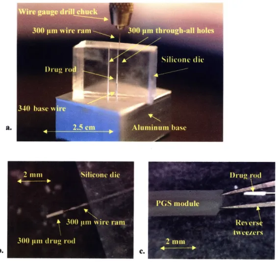
A 10:1 mixture of Sylgard® 184 silicone elastomer base to curing agent (Dow Coming Corporation, Midland, MI) was poured into an aluminum mold of similar design to that in Fig. 6a strung with two 300 gim diameter wires (Small Parts, Inc) to fabricate the silicone die. The mixture was cured at 700C for 3 hours and cut into slabs of roughly 2 x 2 x 1 cm dimensions. A slab was mounted upon an aluminum base with an embedded 340 pm wire which penetrated one of the two 300 gtm diameter cores of the silicone die to an approximate height of 3 mm (Fig. 9a). CIP powder was deposited on top of the silicone slab and packed into the core of the die using a 300 ipm steel wire ram that was secured within a wire gauge drill chuck. The compressed CIP would expand the diameter of the die core forming a depot during the packing procedure but would shape into rods of 300 pm diameter and 1-2 mm length upon exiting the silicone die (Fig. 9b). These drug rods would remain attached to the end of the steel wire ram, allowing for positioning into the core of a PGS module held open by clamped reverse tweezers (Fig. 9c).
Fig. 9: CIP drug rod casting process
CIP rods were packed and cast in a 300 pm diameter silicone die into rods of 1-2mm in
length (a). The rods remained attached to the 300 pm wire ram upon exiting the die (b) and were loaded into a PGS module held open by reverse tweezers (c).
2
Silicone (lie
300 wn %%irc rarn
300 pin druo rod
DI-11( rod
I)GS module
ReN ersý,
3.0 Materials and Methods
3.1 PGS/PLGA degradation experiments
The PGS pre-polymer was synthesized by polycondensation of 1.4 moles each of glycerol (Sigma-Aldrich, St. Louis, MO) and sebacic acid (Aldrich) at 1300C under argon for 24 hours before reducing the pressure from 1 torr to 40 mtorr. The reaction was maintained at 40 mtorr and 120 'C for 30 hours. The pre-polymer was cooled and stored in a dessicate environment at room temperature until further use. A silicon wafer was spin-coated with sucrose solution to form a sacrificial release layer and 7g ± 0.05 g of the pre-polymer was melted and spread across the surface at 160 OC to form a 1 mm thick PGS sheet. The pre-polymer sheet was further cross-linked at 130 OC and 50 mtorr for 48 hours with a liquid nitrogen trap attached to the vacuum line. The PGS sheet was incubated in de-ionized water (diH20) for 24 hours to induce
delamination from the wafer via sucrose dissolution. The sheet was removed from the wafer and serially placed in solutions consisting of 100% ethanol (Pharmco, Brookfield, CT) for 24 hours, 100% diH20 for 24 hours and dried at 70 OC for 24 hours. Circular discs were cut from the sheet
using an 8 mm diameter punch. 8 mm PLGA discs were formed via hot pressing of 0.3g PLGA powder at 121 oC and 5000 pounds for 3 minutes. The PLGA was a 50:50 lactide:glycolide polymer with MW of 66 kDa and degradation time frame of 3-4 weeks purchased from Lakeshore Biomaterials (Birmingham, AL).
The PGS and PLGA discs were weighted and deposited in pre-weighed 1.5 mL vials and immersed in 1 mL of 0.1 mM NaOH solution, pH-~10. An additional line of PGS discs were weighed and placed in a 24-well plate and each was immersed in 1 mL of SurineTM Negative synthetic urine, pH-7.4 (Dyna-Tek Industries, Lenexa, KS). All samples were placed on a rotator at low speed and incubated at 37 'C. Each week throughout a course of six weeks, all
samples were re-suspended in NaOH solution or synthetic urine and a subsection of samples were withdrawn for assaying. Three discs of each type (PGS in NaOH, PLGA in NaOH, PGS in urine, and PLGA in urine) were rinsed in 1 mL diH20 and dried overnight at 60 'C in the assay protocol. The discs were then immersed in 100% ethanol (Pharmco) for 24 hours followed by immersion in diH20 for 24 hours for the PGS samples and drying overnight at 60 OC for the
PLGA samples. The PGS samples were then dried overnight at 60 TC, and all samples were
weighed after the final drying. The final dry weight was recorded to monitor degradation over time.
3.2 CIP HPLC method and stability testing
Ciprofloxacin (Fluka, St. Louis, MO) and ciprofloxacin-HCI (Aurobindo Pharma Ltd, Hyderabad, India) were each dissolved in both diH20 and 0.1 mM NaOH solution at
concentrations of 10 [pg/mol and stored at 37 OC for a period of 4 weeks. 1 mL aliquots of each solution were taken at roughly 1 week intervals and assayed for percent CIP purity through
HPLC-UV analysis using the following described method. An Atlantis T3 100 A 250 mm x 4.6
mm, 5 pm column (Waters Corp, Milford, MA) was used with an eluting system consisting of acetonitrile (EMD Chemicals Inc, Darmstadt, Germany) as the mobile phase and 0.01 M phosphate buffer (NaH2PO4:H3PO4 2:1, pH -2.8) as the aqueous phase. Sodium monophosphate
(NaH2PO4) was purchased from Mallinckrodt Baker, Inc. (Phillipsburg, NJ) and phosphoric acid
(H3PO4) was purchased from Sigma Aldrich. A gradient method was applied over 10 minutes
with 20:80 % mobile phase: aqueous phase at time 0 min, adjusted to 70 % mobile phase by 8 min. and 20 % mobile phase by 9 min. with a constant flow rate of 1 mL/min on an 1100 series HPLC solvent delivery system (Agilent Technologies, Santa Clara, CA). Detection was
performed with a UV-visible detector set at 275 nm with an injection volume of 20 pL per sample. The limit of detection was approximately 50 ng/mL for ciprofloxacin in aqueous diluents and the retention time was around 5.6 minutes
3.3 Release Experiments
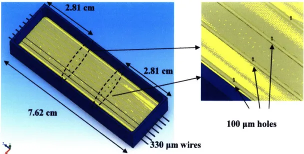
4 g of the PGS pre-polymer was melted at 160 'C in an aluminum mold penetrated longitudinally with 0.013 inch (-330 pm) diameter steel wires (Small Parts Inc, Miramar, FL) which was manufactured in-house as described in section 2.1. The pre-polymer was cured at 135
TC and 50 mtorr for 48 hours with a liquid nitrogen trap attached to the vacuum line. Laser
microablation methods as described in section 2.2 were used to generate orifices of differing diameters (70-150 pm) in the PGS casting at locations above the embedded steel wires as indicated in Fig. 10. The casting was then soaked in diH20 for 24 hours at 60 OC before
removing the wires and PGS casting from the aluminum mold followed by overnight immersions in 100% ethanol, diH20 and drying at 60 OC as described previously. The casting was roughly
1.5 mm thick and was cut into modules of approximate dimensions 10 mm x 1.5 mm, each
containing a release orifice located about mid-length (Fig. 11) except for control modules and
100 pm holes n wires
Fig. 10: Schematic illustration of mold used to cast PGS.
Locations of laser-drilled orifices are indicated by the dashed ellipses and their relation to the embedded steel wires in the zoomed-in illustration to the right.
Ciprofloxacin-HCI (Aurobindo Pharma, Ltd) was loaded into the PGS modules and packed into a rod of 3-5 mm in length using the method described in section 2.3. Steel wires of diameter 0.015 inches (380 pm) purchased from Small Parts Inc were used as plugs to prevent CIP-HCl from leaking out the module ends. The approximate average thickness of each module side and the diameter of each packed CIP rod was measured on an Axiovert 200 inverted light microscope (Carl Zeiss Microlmaging Inc, Thornwood, NY) at 2.5X using the measurement feature of the accompanying AxioVision 3.1 imaging software. The modules were each mounted within 6 mL glass vials using UV-cure epoxy (Dymax Corporation, Torrington, CT) and immersed in either 2 mL diH20, 0.01 mM NaOH (pH - 8) or 0.1 mM NaOH (pH -10) solution. The vials were stored at 37 "C and tilted on an angle so that the modules were completely covered by solution.
Fig. 11: Schematic drawing of CIP-loaded PGS release modules containing 100 pm release orifice and steel wire plugs.
1 mL of solution from each vial was withdrawn for concentration analysis and 1 mL of solution was replaced at each time point within a two week period. CIP-HCl quantification analysis was performed for each sample using the HPLC-UV detection method described previously. Standards ranging from 100 ng/ml to 30 mg/ml CIP-HCl were used to construct a calibration curve. The modules were cut open at the end of each release experiment, and the drug content was extracted to determine the remaining CIP-HCl mass by HPLC-UV analysis.
4.0 Results
4.1 PGS/PLGA Degradation Experiments
The in vitro degradation profile of PGS at 37 OC was tested in both synthetic urine and sodium hydroxide solution at pH -10 over a time period of six weeks and compared to the profiles of a 50:50 PLGA co-polymer exposed to the same conditions. The aim of this series of
experiments was to monitor the degradation of PGS under the effects of temperature and alkaline
pH (mimicking conditions of the seminal vesicle environment) in comparison to more neutral
urinary conditions (synthetic urine, pH-7.4) and another biodegradable polyester (PLGA) with a reported degradation timeframe of 3-4 weeks. Other goals were to measure the degradation rate constant of PGS at pH-10 by measuring the loss in mass over time and to preview the structural stability of a PGS device in an alkaline environment over a three week time period.
0o E h. U)
OR
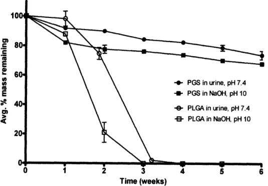
Lu Time (weeks)Fig. 12: Mass loss of PGS and PLGA from in vitro hydrolytic degradation over a six week
time period at 37 OC. Error bars represent standard deviation among triplicates for each time point and condition.
Results are shown in Fig. 12 for the four conditions analyzed in which the average percent mass remaining (m/mo) among each triplicate of samples at each time point is plotted. Error bars are calculated as the standard deviation in m/mo for each triplicate. The surface eroding properties of PGS and bulk eroding properties of PLGA are clearly demonstrated by this data and are in agreement with literature descriptions.35 '37 PGS is shown to degrade with a linear relationship between remaining mass and time when normalized by initial mass in both urine and NaOH solution, a feature characteristic of surface eroding polymers.3771 ' The PGS discs also maintained their original shape throughout the experiment, resisting both deformation and swelling. The degradation profiles of the 50:50 PLGA samples show characteristic bulk erosion, in which water permeates rapidly into the core of the sample and causes catastrophic mass loss to occur before the third week of the experiment. The PLGA discs lost both their shape and mechanical integrity
within the first week of the experiment, forming gel-like pellets at the bottom of the tubes.
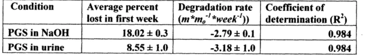
The degradation rate of PGS in both urine and NaOH was calculated by a linear fit of average m/mo vs. time through each time point except time zero, as the mass loss between time zero and week 1 was much more significant than the rest of the curve. Table 1 shows calculations for PGS degradation rate in both NaOH and urine, and the accelerated mass loss that occurred during the first week for each condition.
Table 1: Summary of linear fitting for PGS mass loss data
Condition Average percent Degradation rate Coefficient of lost in first week (m *mo' *week-')) determination (R2
)
PGS in NaOH 18.02 ± 0.3 -2.79 ± 0.1 0.984 PGS in urine 8.55 ± 1.0 -3.18 ± 1.0 0.984
Percent mass lost of PGS in NaOH during the first week is approximately 2-fold higher than the mass loss in urine, although degradation rates after the first week are quite similar.
PGS is found to maintain a significant majority of its mass integrity over the desired time period even when exposed to an alkaline environment, as the average (rnm/o) did not drop below
75 % after 3 weeks or 70 % after six weeks. Both PGS and PLGA have more rapid degradation
at higher pH as compared to neutral conditions as both are polyesters which are subject to
base-catalyzed hydrolysis of ester bonds. The effect in PGS is less dramatic however, as stable, linear
mass loss is soon recovered with a comparable degradation rate to that observed at pH 7.4 (Table
1). This recovery may be due to a neutralizing effect from the production of acid monomersduring degradation, although all remaining samples were re-suspended in fresh NaOH at the beginning of each week of the experiment.
4.2 Summary of CIP HPLC method and stability testing
CIP eluted around
5.6
minutes, as shown in the chromatogram of a 10 gg/ml standard in
Fig. 13. The linear range of quantification was between 1-30 pg/ml. The peak and trough
eluting around 4 minutes is a standard detection response to the 20 .l injection. Both CIP and
CIP-HCI retained greater than 99 % purity (determined as the ratio of CIP peak area over the
total peak area) during the stability experiment in both diH20 and pH
-
10 NaOH solution when
stored at 37 'C over 4 weeks. The area of the CIP peak also remained roughly constant for each
solution. CIP was thus determined to be chemically stable in alkaline solution and that CIP
could be left in solution between sample collection and analysis for up to 4 weeks without
significant stability concerns. No significant difference between the elution or detection of CIP
relative to CIP-HCl was observed, thus the hydrochloride form was used for the release
experiments due to its higher solubility in water.
pMVWDI AFlw.nq276 mIEO ) PMPI, Flow
mom.
Fig. 13: HPLC chromatogram showing CIP retention time around 5.6 minutes
4.3 CIP Release Experiments
Photographs of PGS modules loaded with CIP-HCI are shown in Fig. 14. Each module was approximately 1 cm long and contained a CIP rod in the range of 3-5 mm in length.
NSTRUMtLNiS & uMltMIta -. ,
Fig. 14: Photographs of PGS modules containing packed CIP rods.
Fig. 14a shows the orientation of the drug payload to the release orifice while Fig. 14b
shows full module lengths with steel wire plugs. -"~~"~-~-;I-I-~~---'^-"-I-~~I---~ -~~~'~^"1^"1`-'~~;-^~I--~--";--~~~~~-
~----~;-Modules with different orifice sizes (70-90, 100, 150 and 300 glm in diameter) and control modules with no orifice were tested in release experiments to characterize the orifice size regime that would provide osmotic-controlled release. CIP release profiles were collected for each module and plotted as cumulated drug mass released vs. time after osmotic induction (Fig. 15). The initial drug payload for each module was calculated by the sum of the total drug amount released during the experiment and the remaining mass extracted from the module at the end of the experiment, both measured by HPLC-UV. The release rate for each profile portrayed in Fig. 15 was multiplied by the average PGS wall thickness measured for each module and plotted for each timepoint after induction as shown and described in Fig. 16.
S100 ptm216±12 jig -- 100 rnm 257 13 g 100 plm 630 ± 24 ig -0- 150 m 255 15 g -- 150 un 264 12 Ig --- 150 pm. 498 22 jg - 70 jm 516 ± 39 tg -"8 80 m 225 ± 10 ug 90 som 312 ± 12 tg 300 pm. 223 + 14 Ig -E- 300 •m. 427 ± 20 g -r- 300 •ut 458 ± 27 pg - 300 It 582 ± 31 g -e- Control. 389 39 pg 0 24 48 72 96 120 144 168 192 216 240 -B- Control. 465 ± 45 pg
Time after induction (hours)
Fig. 15: CIP release profiles from PGS modules with different sized orifices.
The induction time was subtracted from each release profile. Induction times were calculated through extrapolation via linear fitting of the first three points from the release regime of each profile. Orifice size is noted in pm and initial drug payload is noted in pg for each drug-loaded module. Horizontal error bars represent error in induction time which was calculated by least squares fitting error analysis. Vertical error bars represent accumulated error of HPLC calibration, pipette uptake, and extrapolation for concentrations measured above 30 pg/ml.
42 V o 0 O.W 0