Design and Use of a Fixed-End Low-Load
Material Testing Machine
by Nicoli M. Ames
Submitted to the Department of Mechanical Engineering in Partial Fulfillment of the Requirements for the Degree of
Bachelor of Science in Mechanical Engineering at the
Massachusetts Institute of Technology
June 2000
©2000 Massachusetts Institute of Technology All rights reserved
Signature of Author ____________________________________________________________________ Department of Mechanical Engineering May 5, 2000
Certified by __________________________________________________________________________ Lallit Anand Professor of Mechanical Engineering Thesis Supervisor
Design and Use of a Fixed-End Low-Load
Material Testing Machine
by Nicoli M. Ames
Submitted to the Department of Mechanical Engineering on May 5, 2000 in Partial Fulfillment of the Requirements for the Degree of Bachelor of Science
in Mechanical Engineering
ABSTRACT
The purpose of this low-load material testing machine is to provide students an opportunity to perform basic material tests on their own instead of watching a lab technician, thus improving the student’s lab experience. The machine proposed is small, low cost, and easy to manufacture, assemble, and operate. Its design is based on a compound flexure mechanism that provides rectilinear motion for uniaxial tension and compression tests. It is actuated by a voice coil and displacement is measured using strain gauges. This thesis outlines some of the basic theory involved in the design and use of this low-load machine. Then it details calibration routines and tension testing procedures. Next, it analyzes results from tension tests. Then it discusses a possible source of error found in the tension tests, a lack of rigidity in the apparatus. Finally, it provides a reasonable solution to the rigidity issue and suggests further testing of the new apparatus before it is available for student use.
Thesis Supervisor: Lallit Anand
T A B L E O F C O N T E N T S
List of Figures ...7 1 Introduction ...9 2 Theory...9 2.1 Specimen Force...9 2.2 Flexure Stiffness ...102.3 Flexure Linear Motion ...12
2.4 Voice Coil Force/Current Relation ...13
2.5 Strain Gauges ...13 3 Experiment...14 3.1 Apparatus ...14 3.1.1 Mechanism Design ...15 3.1.2 Mechanism Manufacturing...15 3.1.3 Strain Gauges ...15 3.1.4 Voice Coil ...15 3.2 Calibration ...15 3.3 Testing Procedure ...16 3.3.1 Specimen Preparation ...16 3.3.2 Tension Test...16 4 Results...16 4.1 Calibration ...16 4.2 Tension Test...18 5 Discussion ...18 5.1 Tension Test...18 5.2 Apparatus ...19 5.2.1 Bending Moments ...19 5.2.2 Temporary Solution...19 5.2.3 Frame Modifications ...19 6 Conclusion...21 Aknowledgements...23 References ...25
L I S T O F F I G U R E S
Figure 1: Force balance of specimen, flexure, and voice coil forces ...10
Figure 2: Flexure consisting of four cantilevered beams ...10
Figure 3: Less complex flexure model showing only half of the entire flexure...10
Figure 4: Shear forces, bending moments and tensile forces in flexure...11
Figure 5: Displaced flexure system with an applied load...12
Figure 6: Voice coil magnet with current carrying copper wire coil...13
Figure 7: Full bridge layout of strain gauges...13
Figure 8: Fixed end low-load material testing machine ...14
Figure 9: Flexure displacement/strain calibration results...17
Figure 10: Flexure stiffness calibration results...17
Figure 11: Voice coil force and current calibration results ...17
Figure 12: Stress-strain curve for aluminum ...18
Figure 13: (l) Bending moments due to specimen force (r) temporary solution resulting in fracture...19
1 INTRODUCTION
The biggest challenge for an undergraduate mechanics and materials laboratory instructor is to be able to involve the students in the experiments. Most material tests in the labs are performed using large, expensive, and/or complex pieces of machinery. This precludes the students from performing the tests themselves because of the liability involved in letting them use this equipment. Students must huddle around a machine as a technician performs a test and gathers data, which leaves the student with the sole task of analyzing the results; this is not a very fulfilling way for the student to spend a two-hour
laboratory session. One way to involve the student more in the laboratory is to find a machine that they can use themselves in order to perform material tests. This machine would need to be small, inexpensive, and easy to operate—the opposite of the machines already in use.
One of the most common tests performed in an undergraduate laboratory is a simple uniaxial tension test. From this test, one can determine some material properties such as the Young’s Modulus, the yield stress, and the ultimate tensile stress. The test is normally performed on a large Instron universal testing
apparatus, a machine capable of applying many kilo-Newtons of force in tension. This large force range is not needed, however, if the size of the specimen being tested is reduced. The combination of a reduced specimen size and a reduced force range results in a smaller required machine. This thesis outlines the design of a relatively small and inexpensive low-load tension machine to be used by students to test thin film materials.
This low-load machine is also low cost, requiring only about .09m2 of a ½-inch aluminum plate for the apparatus, a voice coil for actuation, four strain gauges for displacement measurement, and a computer with the proper interface equipment to tie it all together. Test specimens are also cheap; they can easily be cut from sheets of inexpensive aluminum foil. In addition, using a compound flexure mechanism insures uniaxial displacement in this device. Also, the interesting geometry of this flexure, along with the unique design of the specimen grips, allow the entire apparatus to be machined with only a few
continuous cuts on one plate of material using either a water jet or a wire EDM. The final apparatus is actually made from one unbroken sheet, so assembly is straightforward (the voice coil, the strain gauges, and some standard sized screws are the only loose parts). Operation of the machine is nearly as easy as its assembly is; two small screws tighten the specimen grips, an increase in voice coil current raises the specimen force, and the displacement is calibrated to correspond to the strain gauge measurement. This thesis outlines some of the basic theory involved in the design and use of this low-load machine. Then it details calibration routines and tension testing procedures. Next, it analyzes results from tension tests. Then it discusses a possible source of error found in the tension tests, a lack of rigidity in the apparatus. Finally, it provides a reasonable solution to the rigidity issue and suggests further testing of the new apparatus before it is available for student use.
2 THEORY
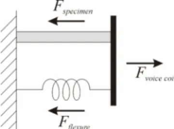
2.1 Specimen ForceThe specimen will be gripped so that one end is fixed and the other end is held by the movable flexure. The flexure can be modeled as a spring that also has one end fixed. The flexure will be actuated by the voice coil, which must also provide the same displacement for the specimen. The force balance for this model is shown in Figure 1.
10
Figure 1: Force balance of specimen, flexure, and voice coil forces
If the voice coil and flexure forces are known, then the force applied to the specimen is simply given by flexure coil voice specimen F F F = − (1) 2.2 Flexure Stiffness
In order to find the flexure force, the flexure stiffness must be known. A simple diagram of the flexure being used is shown in Figure 2. Notice that it is simply a combination of four cantilevered beams arranged in a manner such that there is no horizontal motion at the load application site.
Figure 2: Flexure consisting of four cantilevered beams
To find the stiffness of the flexure shown in Figure 2, the problem can be simplified as a series combination of two of the flexure structures shown in Figure 3.
Figure 3: Less complex flexure model showing only half of the entire flexure
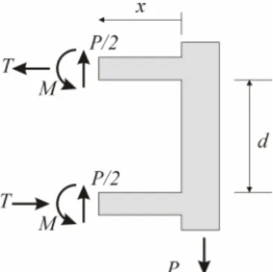
The stiffness of this flexure can be determined by “cutting” the beams and analyzing the shear and tensile forces and bending moments inside the beam as shown in Figure 4.
Figure 4: Shear forces, bending moments and tensile forces in flexure Summing the moments around the lower right corner of Figure 4 results in
( ) ( )
P x P x Px MTd+2 = 2 + 2 = (2)
So that the bending moment in each of the beams is given by
(
Px Td)
EIyM = − = ′′
2 1
(3)
Integrating once yields
1 2 2 4 C Tdx Px y EI ′= − + (4)
The rigid connection at each end gives the boundary conditions
( ) ( )
0 = ′ =0′ y L
y (5)
Substituting these into Equation 4 gives
d PL T C 2 , 0 1= = (6)
Then, integrating Equation 4 once gives
2 2 3 8 12 C PLx Px EIy= − + (7)
The rigid wall on the left side does not move, resulting in the boundary condition
( )
L =0y (8)
Substituting this into Equation 7 gives
24
3 2
PL
12
So that the displacement at the load application sight, where x = 0, is then
( )
EI PL y 24 0 3 = (10)The stiffness of this structure is then given by Hooke’s Law to be
( )
3 24 0 L EI y P F k = = = δ (11)Then, a series combination of two of these flexures to form the overall structure shown in Figure 2 results in an overall stiffness of 3 1 12 2 1 1 L EI k k k K = = + = − (12)
So, if the displacement, δ, of the flexure at the load site is known, then the force exerted on the flexure is simply δ 3 12 L EI Fflexure = (13)
2.3 Flexure Linear Motion
Linear motion of the flexure is very important. If the motion is nonlinear, then the force/displacement being applied to the specimen will not be uniaxial, and the flexure would be an unsuitable mechanism for a tension-testing machine. When a load is applied to the flexure, it displaces as shown in Figure 5.
Figure 5: Displaced flexure system with an applied load.
The displacement of the load site in the x-direction is given by X, which is the sum of the shrinkage of all the flexures in the x-direction. The two inner flexures must both shrink the same total distance, ∆x1, in the
x-direction because they are rigidly attached to the same surfaces at each end. The two outer flexures
must also shrink the same total distance, ∆x2, in the x-direction. Now, because both sets of flexures have
the same stiffness, and they all share the load, P, equally, they must all shrink the same absolute distance in the x-direction. In addition, the outer flexure system is arranged oppositely of the inner flexure system, so its shrinkage in the x-direction is negative in magnitude of the inner flexure system’s shrinkage. This all results in the relation
2
1 x
x =−∆
Therefore, the displacement of the load site is then given by 0 1 1 2 1+∆ =∆ −∆ = ∆ = x x x x X (15)
So, the load site does not translate in the x-direction—its motion is perfectly linear in the y-direction. [3,4].
2.4 Voice Coil Force/Current Relation
The voice coil is a simple device. It consists of a cylindrical magnet encompassed by a coil of copper wire as shown in Figure 6. The current, I, acts along the length of the wire, l, which lies in the
?ˆdirection. The magnetic field, B, radiates from the center of the magnet in the rˆ direction. The force of the voice coil, F, acts in the zˆ direction.
Figure 6: Voice coil magnet with current carrying copper wire coil The relation between these quantities is given by
B l
Fr=Ir× r (16)
In the case of the voice coil the current always acts perpendicular to the magnetic field, so, through use of the “right hand rule”, it becomes clear why the force must always act in the zˆ direction. The most
significant quality of the voice coil, however, is its very dependable linear relationship between current and force (because the wire length and magnetic field are fixed). [5]
2.5 Strain Gauges
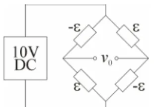
The number of active strain gauges used (from one to four) and their position on a strained object determines the maximum sensitivity that can be achieved. In this case, four strain gauges will be used to measure the bending strain in the region of the flexure that strain is expected to be the highest, near the ends. Two strain gauges will measure positive strain, while the other two will measure negative strain. These gauges are combined into a Wheatstone Bridge as shown in Figure 7.
Figure 7: Full bridge layout of strain gauges.
This particular setup is four times more sensitive than using a single strain gauge with three dummy resistors. In addition, this setup also compensates for temperature effects and axial and torsional strain components, so that only strains due to bending are measured. [1]
14
It is desired that flexure strain and displacement be related linearly through out the range of the flexure so that calibration is simple. The strain in one of the flexures is given by
EI My − =
ε (17)
where M is given by Equation 3 and y is equal to one-half of the flexure thickness, h. Substitution then gives
(
)
(
)
δ ε 3 2 3 8 2 L x L h EI x L Ph − = − = (18)where δ is the displacement. When x = 0 or x = L, the strain will be greatest, which will provide the best resolution for displacement measurement. Substitution of x = 0 yields a strain of
δ ε 2 2 3 L h = (19)
So, strain is linearly dependent on the displacement of the flexure. Calibration results should also show this linear relationship.
3 EXPERIMENT
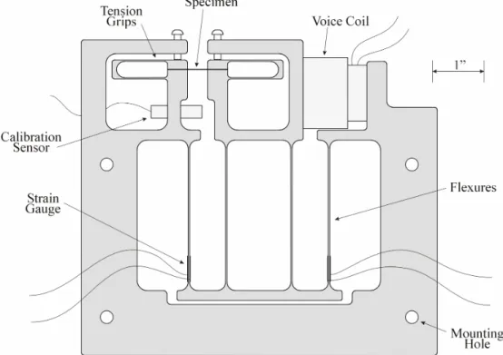
3.1 ApparatusThe entire assembled apparatus is shown in Figure 8. This section overviews the design, manufacture, and assembly of the apparatus.
3.1.1 Mechanism Design
The flexures were designed to have a minimum stiffness in order to maximize the limited power of the voice coil. To minimize stiffness, the flexure stiffness was minimized and the length maximized (see Equation 13). Extra room on each side of the flexure was cut out so that there would be enough room to be able to mount strain gauges on the outer flexures. To protect the flexure from plasticity, the maximum travel distance of the flexure was set by causing the flexure to hit the frame at a displacement of ¼” from the center position.
The specimen grips are also designed as small flexures so that the gripping surfaces remain close to parallel no matter what thickness of specimen is inserted in the grips. To close the grips on the specimen, each of the setscrews is simply tightened.
3.1.2 Mechanism Manufacturing
The complete mechanism is machined from one ½” aluminum plate. All of the cuts were done using an abrasive water-jet machine, except for the two small cuts to separate each of the specimen grips, which were done using a wire EDM. One nice result of using the wire EDM to open up the grips is that the resulting surface is very rough, which prevents the specimen from slipping. Any necessary holes for screws or for mounting the sensors and actuators were made with a drill press
3.1.3 Strain Gauges
The four strain gauges are mounted on the two outer flexures, with one gauge on the left side of the given flexure, and the other gauge on the right side. Therefore, two gauges are reading positive strain, and two gauges are measuring the negative of the same strain. The output of these gauges is sent to a National Instruments 1321 Offset-Null and Shunt Calibration Terminal, which is connected to a NI SCXI-1121 Channel Isolation Amplifier. NI LabView software is used to pick up this signal and convert it to strain. The minimum strain that can be recorded with this setup is 1.38 x 10⁻⁶ strain.
3.1.4 Voice Coil
The voice coil is mounted in its fully extended position to provide the maximum range in tension. If a compression test were necessary, then spacers would be inserted so that the voice coil would be mounted in its fully closed position. Current is supplied to the voice coil via an Agilent Technologies E3648A Programmable DC Power Supply. The power supply may be controlled manually or remotely by LabView. If LabView is used, then a closed loop displacement control system can be developed using the strain gauge reading as feedback for the voice coil force.
The specifications for the voice coil state that it has a maximum force of 15.5 N with a current 1.49 A. They also state that the force/current relation is 10.45 N/A, however, this will be verified during calibration.
Special care should be taken when turning on the power supply or the power supply outputs because it produces a voltage spike across the output terminals, even if the current and voltage are set to zero. Therefore, a specimen should not be loaded in the apparatus when the power supply or the power supply outputs are switched on in order to avoid damaging the specimen.
3.2 Calibration
Several calibrations need to be performed. For displacement calibration, a Kaman Instrumentation SMU 9000-5U eddy current sensor is used. A set of brass masses is used for stiffness calibration. All
16
The first calibration determines the relationship between flexure strain and flexure displacement. It is performed by varying the voice coil current while the eddy current sensor measures the flexure displacement and the strain gauges measure the flexure strain.
The second calibration determines the flexure stiffness. For this calibration, the apparatus needs to be turned on its side so that the right edge shown in Figure 8 is horizontal, and the voice coil is removed. Masses are then placed on the flexure in the area near the right specimen grip while the flexure strain is recorded. The strain measurement is then converted to displacement. The flexure stiffness then is the force caused by the masses on the flexure divided by the displacement of the flexure.
The third and final calibration determines the force and current relationship of the voice coil. For this test, the apparatus is returned to its normal upright state and the voice coil is reinstalled. The calibration is performed by increasing the voice coil current while measuring the flexure strain. The flexure strain can now be correlated to the flexure force by using the stiffness and displacement relationships. The voice coil force is then equal to the flexure force.
3.3 Testing Procedure
3.3.1 Specimen Preparation
Specimens may be made from any desired material. For metal specimens, it is easiest to obtain the material in the form of a foil. Rubbers are best obtained from thin rubber sheets. To cut the specimen, simply apply a razor blade to the material and punch it through the material with a hammer. This method can be used to create a nice rectangular test specimen. It is best to avoid dragging the razor blade to cut the material because that process will create undesirable effects at the edge of the specimen. In the future, a punch will be made that will be capable of producing dog bone shaped specimens.
3.3.2 Tension Test
The first step is to turn the power supply and the output terminals on to zero current and zero voltage in order to stabilize the voice coil. This should be the first step so that the specimen is not accidentally damaged. Next, the specimen is slid into the grips using tweezers; it may be necessary to hold the grips open to do this. The specimen should be parallel to the direction of the flexure movement in order to maintain uniaxial tension test conditions. Once the specimen is positioned, the setscrews are tightened in order to secure the specimen in the grips. Now the strain gauge bridge needs to be zeroed. This can be accomplished by turning a screw on the SCXI-1321 terminal while monitoring the strain in LabView. The apparatus is now ready to perform a test. The voice coil current is increased in either 1 mA or 10 mA steps as the corresponding flexure strain is recorded. This continues until either the specimen breaks or the end of the range is reached.
4 RESULTS
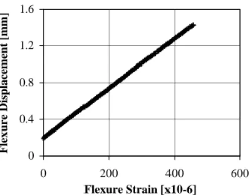
4.1 CalibrationThe results of the flexure strain versus displacement calibration are shown in Figure 9. The data forms an almost perfect line. From the slope of the data, it was determined that the conversion factor is 2.71x10⁻³
0 0.4 0.8 1.2 1.6 0 200 400 600 Flexure Strain [x10-6] Flexure Displacement [mm]
Figure 9: Flexure displacement/strain calibration results.
The results of the flexure stiffness calibration are shown in Figure 10. Once again, the data forms an almost perfect line. From the slope of the data, it was determined that the flexure stiffness is 0.88 N/mm. Using Equation 12 with the values b = 12.7 mm, h = 0.75 mm, L = 75 mm, E = 70 GPa, the predicted stiffness is 0.889 N/mm, a very nice approximation.
0 0.2 0.4 0.6 0 0.2 0.4 0.6 0.8 Flexure Displacement [mm] Flexure Force [N]
Figure 10: Flexure stiffness calibration results.
The results of the voice coil and force calibration are shown in Figure 11. The data still forms an almost perfect line. From the slope of the data, it was determined that the force/current relationship is 0.0109 N/mA. The voice coil data sheet reports a force/current relationship of 0.01045 N/mA, so the calculated value is definitely within the appropriate range.
0 0.4 0.8 1.2 0 50 100 Current [mA] Force [N]
18 4.2 Tension Test
The stress-strain curve for a tension test of an aluminum foil specimen is shown in Figure 12. The specimen had a thickness of 25.4 µm, a width of 1.00 mm, and a gage length of 10.8 mm. The resolution of the strain gauge equipment is highly evident in the steps in the plot. The finest flexure strain that the gauges are capable of reading is 1.38 x 10⁻⁶, which corresponds to a displacement of 3.75 µm, or for this case, a specimen strain of about 350 x 10-6. The steps on the plot are indeed separated by approximately 350 x 10-6 strain. Using the data from Figure 12, the Young’s Modulus of the aluminum specimen appears to be about 45 GPa, for both the initial elastic portion and the unloading portion of the curve. The Young’s Modulus of aluminum should be close to 70 GPa. Repeated tests on different aluminum
specimens did not improve the error in the Young’s Modulus, therefore, the tension test is producing highly undesirable results.
0 40 80 120 160 200 240 0 0.003 0.006 0.009 0.012 0.015 0.018 Strain Stress [MPa] Stress-strain curve Unloading Young's Modulus E = 45 GPa
Figure 12: Stress-strain curve for aluminum
5 DISCUSSION
5.1 Tension Test
The tension test did not produce desirable results; the displacement resolution was not fine enough to produce a smooth curve and the Young’s Modulus of the aluminum had an error greater than 30%. The displacement resolution can be improved by buying better data acquisition hardware, increasing the thickness of the flexures, or lengthening the flexures (see Equation 19). These changes in the flexure geometry, however, will increase the flexure stiffness, which needs to be minimized. Therefore, a good trade off between flexure stiffness and displacement resolution needs to be found. Further investigation needs to be done to find the source of the incorrect Young’s Modulus for the test specimens.
5.2 Apparatus
Upon closer examination, it became obvious that the error in the Young’s Modulus was due to displacement measuring errors caused by bending in the frame, which was thought to be rigid.
5.2.1 Bending Moments
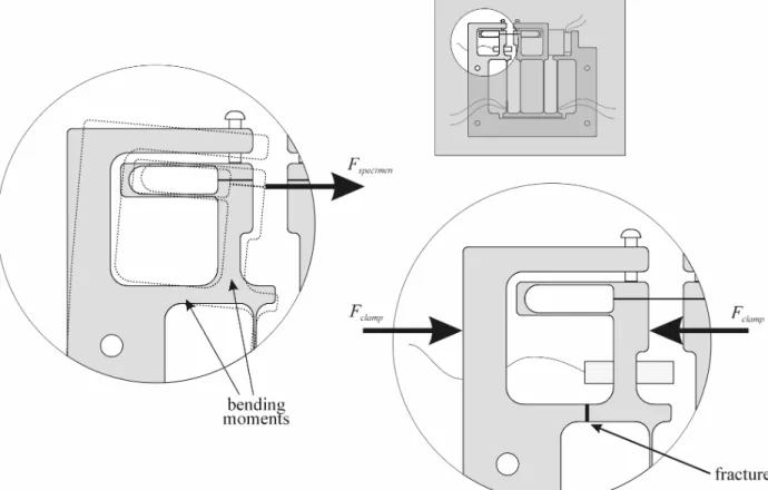
The left image in Figure 13 illustrates the effect that the specimen force can have on the frame of the apparatus. The force causes the entire grip section to rotate clockwise. This rotation is not accounted for in the calibration of the strain gauges with displacement. Therefore, the specimen is actually undergoing less displacement than what the strain gauges measure. This would have the effect of lowering the measured Young’s Modulus.
5.2.2 Temporary Solution
A temporary solution was devised to stiffen the grip region in order to reduce the rotation and improve the tension test results. The idea was to place a c-clamp so that it would exert the forces illustrated in the right image of Figure 13; however, this had a very negative effect, it caused the frame to fracture. The temporary solution actually accentuated the fatal flaw of this design, a lack of rigidity in the frame.
Figure 13: (l) Bending moments due to specimen force (r) temporary solution resulting in fracture
5.2.3 Frame Modifications
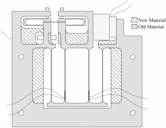
In order to achieve better results, the frame needs to be modified to be more rigid. This can be accomplished by increasing material in the frame in areas that were previously too thin. A possible solution is shown in Figure 14.
20
First, the area to the right and left of the flexures was very open in order to allow easy installation of the strain gauges; this weakened the very thin arms above them. If the strain gauges are moved to the middle flexures, then the open area can be filled in.
Second, the open area in the middle of the left grip region can be filled in with material to provide the stiffness that would have been partially obtained by using the c-clamp. A small region needs to remain open, however, to allow the Kaman sensor to be bolted into place. The open area in the right grip region can also be filled in, however, some room needs to remain open so that the screw that holds the voice coil in place can be inserted.
Third, the region between the two grips where the Kaman sensor is located had been designed to be wider than that where the specimen grips are located. This was because it was originally thought that the Kaman needed a minimum amount of space to be positioned properly. While this is still true, the amount of space originally designed can be reduced.
The fourth and final suggested modification is to move the voice coil up a bit and increase the material in the arm below it. This is probably an unnecessary modification, as there are no large forces acting on this arm, but it cannot hurt to make it more rigid.
6 CONCLUSION
The basic concepts of the low-load material testing apparatus as outlined in Section 2 have proven to be effective. Namely, the calibration factors are linear, the flexure appears to apply rectilinear motion to the specimen, and the actuators and sensors seem to be operating very reliably.
Unfortunately, the tension test results on aluminum provided by the original design are very undesirable. The results showed values of Young’s Modulus for aluminum to be near 45 GPa, when it should be 70 GPa. This large error is not acceptable, even in the casual environment of an undergraduate laboratory. With a few modifications, however, the device may show better results. The most important modification is to improve the rigidity of the frame. Once this has been enhanced, and the effect of grip rotation reduced, further testing should be done to determine if there are more design flaws in the apparatus. Also, if desired, a higher resolution data acquisition system for the strain gauges could be implemented. Once further testing has been done, and satisfactory results are obtained, then this machine can be made available for student use.
A K N O W L E D G E M E N T S
I would like to thank my advisor Professor Lallit Anand for providing me with the concept for this thesis and supplying me ample resources so that it could all be done. I would also like to thank Sauri
Gudlavalleti and Brian Gearing. Without their knowledge of flexures, low-load tension testing machines, voice coils, water jets, and whatever else, this thesis could never have been done.
R E F E R E N C E S
1. Beckwith, T. G., Marangoni, R. D., & Lienhard, J. H. (1995). Mechanical Measurements (5th ed.). Reading, MA: Addison-Wesley.
2. Gere, J. M., & Timoshenko, S. P. (1997). Mechanics of Materials (4th ed.). Boston: PWS Publishing Company.
3. Jones, R. V. (1951). Parallel and Rectilinear Spring Movements. Jounral of Scientific Instruments, 38, 38-41.
4. Smith, S. T., & Chetwynd, D. G. (1992). Foundations of Ultraprecision Mechanism Design: Vol. 2. Developments in Nanotechnology. Gordon and Breach Science Publishers: Switzerland.
5. Young, H. D., & Freedman, R. A. (1996). University Physics (9th ed.). Reading, MA: Addison-Wesley.