Design as Exploring Constraints
byMark Donald Gross S.B. Art and Design
Massachusetts Institute of Technology
1978
SUBMITTED TO THE DEPARTMENT OF ARCHITECTURE IN PARTIAL FULFILLMENT OF THE REQUIREMENTS OF THE DEGREE OF
DOCTOR OF PHILOSOPHY IN DESIGN THEORY AND METHODS
AT THE MASSACHUSE1TS INSTITTE OF TECHNOLOGY FEBRUARY, 1986
@ Mark Donald Gross 1985
The Author hereby grants to M.I.T. permission to reproduce and to distribute publicly copies of this thesis document in whole or in part.
Signature of the author
Mark Donald Gross Department of Architecture October 31, 1985 Certified by N. John Habraken Professor of Architecture Thesis Supervisor Accepted by Stanford Anderson Chairman Departmental Committe for Graduate Students
MiASSACHIJSETT S iNSTiT0 ~t-OF TECHNOLOGY
FEB 2 41986
Design as Exploring Constraints
by
Mark Donald Gross
Submitted to the Department of Architecture on October 31, 1985
in partial fulfilment of the requirements for the Degree of Doctor of Philosophy in Design Theory and Methods.
ABSTRACT
A theory of designing is proposed, developed, and illustrated with examples from the
domain of physical form. Designing is seen as the exploration of alternative sets of constraints and of the regions of alternative solutions they bound. Designers with different objectives reach different solutions within the same set of constraints, as do designers with the same objectives operating under different constraints. Constraints represent design rules, relations, conventions, and natural laws to be maintained. Some constraints and objectives are given at the outset of a design but many more are adopted along the way. Varying the constraints and the objectives is part of the design process. The theory accounts for various kinds of expertise in designing: knowledge of particular constraints in a design domain; inference--calculating the consequences of design decisions; preference--using objectives to guide decision-making; and partitioning--skill in dividing a large and complicated design into sets of simpler pieces, and
understanding the dependencies between decisions. The ability to manage ambiguity and vagueness is an important aspect of design expertise.
A computational model supporting the theory is proposed and its implementation
discussed briefly. The constraint explorer, a computational environment for designing based on constraint descriptions is described. We see how the constraint explorer might be used in connection with a simple space-planning problem. The problem is taken from the procedures of the Stichting Architecten Research (S.A.R.), a specific architectural design methodology developed to help architects systematically explore layout variability in alternative floorplan
designs. Finally, a selected review of related work in constraint-based programming
environments, architectural design methods, and the intersection of the two fields is presented.
Thesis Supervisor: N. John Habraken Title: Professor of Architecture
MASSACHUSETTS INSTITUTE
OF TECHNOLOGY
FEB 2 41986
LIBRARIES
Acknowledgements.
Acknowledgements.
I am grateful to the following people.
My parents, Sonja Osaki Keller Gross and Eugene Paul Gross, for making me in the first
place, for showing me the beauty of nature, and for encouraging me to follow my interests.
My dissertation committee, for their patience, intellectual community, continued confidence,
and friendship; in particular,
Aaron Fleisher, for good arguments and hard questions;
N. John Habraken, for revealing a new way to understand built environments;
Seymour Papert, for articulating a vision of the computer as laboratory for learning. Annette Dula, who taught me how to write, using this dissertation as a vehicle, and for continuing and patient criticism throughout the writing.
Jean Nilsson, whose insightful comments are always extremely useful.
Catherine Chimits and Fred Wu, who intrepidly implemented parts of the constraint explorer in constantly changing computing environments, and for continued interest in and criticism of the ideas presented here.
Gary Drescher, David Levitt, Margaret Minsky, and everyone at the Atari Cambridge Research Laboratory (1982-1984) for being a stimulating intellectual community. I am especially lucky to have been part of this unique group of friends that also includes many of the other people named on this page.
Danny Hillis and Ken Haase for suggesting some good references early on.
Steven Ervin, for helping to debug many of the ideas, for patiently sorting out confused arguments, and for following in my footsteps nevertheless; Sandy Isenstadt for improving an early draft of chapter two; Ming Wang for good discussions at an early stage.
Coral Software Corporation, for their dedication to excellence in personal computing and for technical support, and Linda Laplante Okun for knowledgeable administrative guidance through M.I.T.
Maurice K. Smith, whose unparalleled clarity in articulating principles of form first convinced me to undertake the present work.
Alfonso Govela and Michael Gerzso, for taking me seriously and directing my early efforts as an undergraduate.
Ranko Bon, Louis Bucciarelli, and William Porter, for asking sharp questions, and Donald Schon, for enthusiastic support despite skepticism; Robert Lawler and Patrick Purcell, for kind support when it was needed most.
-Table of Contents
Table of Contents
1. Introduction 1
2. Design as Exploring Constraints 8
3. Use of the Constraint Explorer 21
3.1 A Brief Scenario 22
3.2 Behind the Scenes in the Constraint Explorer 28
3.3 Dimension Constraints 38
3.4 Position Constraints 44
3.5 A Position Constraint 56
4. Parts, Prototypes, and Dependencies 60
4.1 Elements and Configurations 60
4.2 Prototypes, Instances, and Individuals 69
4.3 Dependencies in the Built Environments 74
5. Floorplan Layouts 80
5.1 The Design of Supports 80
5.2 Exploring Arrangements of Functions in the Floorplan 84
5.3 Describing the Site 96
5.4 Function Norms 99
5.5 Position Rules 101
6. The Parts of the Program 103
6.1 The Overall Organization 103
6.2 Data Structures 106
6.3 Example 111
6.4 A Closer Look at the Parser and Solver 117
7. Review of Other Work 122
7.1 Overview 122
7.2 Simon's Constraint Formulation of Design 125
7.3 Models and Methods of Architectural Design 128
7.4 Computers and Computational Techniques 131
7.5 Discussion and Further Work 137
References 139
-Introduction
CHAPTER 1
Introduction
The art of design involves considerable expertise. We do not learn this expertise--how to design--explicitly, as a set of procedures to follow, as for example, we learn how to add, subtract, and multiply. Rather, we learn to design gradually, by observing more expert designers, studying designs that are known to be good, and through constant practice and criticism. We learn many techniques, rules-of-thumb, formulae, and tricks, but never a systematic method. Many design disciplines are now approaching a "complexity barrier" [Winograd 73] where traditional methods fail
to produce acceptable solutions. More systematic design methods are needed to coordinate the efforts of teams of more than a very few designers, and also to tackle more complex problems. This thesis proposes a theoretical framework for
understanding design processes, viewing design as exploring constraints and alternatives. The test of this theoretical framework shall be in the performance of a computer program that implements the operations of the theory. The dissertation also describes this computer program, called "the constraint explorer".
Some will object strenuously to the idea of a systematic design method, arguing that design is a creative endeavor and that efforts to make an explicit account of the design process remove some essential artfulness. The objection is often amplified when the efforts involve a computer, and to many readers, the word
Introduction 2
"constraint" connotes an unpleasant restriction of free will and creativity. * It is not my intent to argue here against this point of view. My purpose is only to advance explicit understanding of design processes. I believe that such an understanding is necessary in order to build a foundation for more comprehensive and powerful ways to design.
The theory presented here is not a normative theory of design; it does not
distinguish good designs from bad ones. It is also not a psychological theory of design; it does not attempt to account for what goes on in designers' minds. Nor does the present
theory prescribe any particular design expertise. That job remains for applications of the theory to particular design domains. For example, we might apply the theory to the design of housing, bridges, or integrated circuits. Each such design domain entails vast amounts of specific expertise. This theory is about how designers manage and
manipulate this expertise. The theory rests on the assumption that designers work within rules, principles, conventions, and laws. We can describe all these as constraints on design attributes, or variables. Then we can see a design process as exploring
alternative sets of constraints and exploring alternative solutions within each set of constraints. These two parts of the process are not seen as separate phases of design; rather they are integrated in time.
We begin to design by selecting a first constraint: "I need 40,000 square feet of floor space", or "bedrooms must be in a quiet part of the house". We add to the
constraints and we change them. We explore alternatives by setting, or fixing the values of design variables. Each fix may affect other parts of the design. For example, the
* One might just as properly call the present theory "design as exploring objectives", or "design as exploring relations". We shall see that constraints, relations, and objectives are intimately related.
Introduction 3
placement of one room may affect the position of another. Thus design expertise involves predicting the consequences of a fix on the rest of the design. Each decision is tentative at first and becomes more definite with time; hence we sometimes need to undo or retract previous fixes.
We work with many constraints. They come from many sources and are more and less flexible. The design of a building, for example, includes structural constraints, use-dimension constraints, temperature constraints, surface-material constraints, and others.
A few constraints, such as gravity, are fundamental laws of nature and cannot be altered;
others, chosen by the designer, can be changed; for example, stylistic conventions or the choice of a construction system. Some constraints are general architectural principles; others pertain only to the design at hand. We select and position building elements so as to meet all these constraints. We realize many constraints operationally, as rules-of-thumb for selecting and positioning material and space elements. The daylight in the hall will be good if there are windows on one side. The building will stand if beams span no more than twelve times their depth. For ordinary practice, these rules-of-thumb suffice; a simple position or dimension rule can often subsume a detailed understanding of structural or daylighting behavior.
Constraints form the boundaries of a multi-dimensional region where each
dimension represents an independent design attribute; each point represents a variant, or alternative solution. For example, we can describe the size of a room using three
variables: height, width, and length. To describe the room's color or its area we must introduce additional variables. These may relate to variables already in use, or they may be entirely independent. Area, for example, is the product of width and length; whereas color is an independent variable.
Introduction
We explore the region of alternatives by trying different values for variables and comparing the results. Designers may have different exploration strategies. Trying extreme settings of values is one strategy. Fixing positions before dimensions is another. To select among alternatives we must have preferences, or objectives. We may prefer long rooms, square rooms, or rooms whose width-to-length ratio is the golden mean. We almost always, however, have more than one objective. For example, we may want both the largest and the least expensive alternative. Usually our objectives do not coincide; therefore we must compromise.
We can compromise among competing objectives by partitioning, or decomposing, the design into pieces and optimizing each piece for a different objective. In designing the foundation of a house, for example, we might optimize for strength, while in designing the wood frame we might optimize for light penetration. We must make some decisions together because they interrelate, while other decisions are easily separated. Based on constraint connectivity, this structuring of decisions can only be performed after the constraints have been stated. Seldom can we partition a design perfectly, but often we can partition a design in different ways.
Rules are essential to design; without them we have only free-expression. The concept of design rule is therefore central to the present enterprise. Architectural design rules specify the allowable building elements--both material elements such as columns, walls, and beams, as well as spaces such as gardens, halls, and rooms--and their proper positions relative to one another and to their built context, or site. How are rules
adopted, adapted, invented, and explored in designing buildings and places? We can obviously use rules to check already executed designs. But rules also play an integral part in the process of defining and exploring designs. We sometimes abstract rules from a
Introduction
traditional building type, then use the rules to generate additional instances of that type. The ability to see patterns in, and abstract rules from a given set of designs is certainly important for the architect, but we shall not address it here.
Many traditional built environments have been studied and described in this way. Examples include work on traditional Japanese houses; San Francisco Victorian house
form, siting, and facades; Spanish hilltowns; and Pompeii courtyard houses [Engel 64; Vernez-Moudon 85; Hille 82; Smith, Hille, and Mignucci 82; Habraken, Akbar, and Liu
82]. All these examples identify a set of elements and the rules to assemble them into
coherent configurations that belong obviously to a certain building type. In his masters thesis, for example, Hille shows that we can understand San Francisco Victorian facades as discrete horizontal and vertical zones with minimum and maximum dimensions. He also shows that the combination of facade elements in these zones is strictly governed by rules. Hille presents these rules and shows how they can be used to generate new variations on the theme [Hille 82].
Design, however, is more than following rules; it is making rules as well. Design concerns inventing and adapting systems of form-organization as well as generating specific forms within a given rule-system. By making new rules and combining and modifying existing ones designers invent new styles and occasionally even new building types. Moreover, the rules are not all decided before the designing begins; rather they are adopted and invented throughout the design process. Rule-making may even continue into the process of building. For example, where the architect has simply said "there shall be bricks", the mason may impose a pattern.
Introduction
Architects seldom express rules explicitly. Even when abstracting rules from a built reference, we draw until we come to understand the building's theme, or system of rules. Then we can invent variations on that theme. Usually the understanding remains
implicit--we do not articulate the rules. One obstacle to explicitness is the lack of a way to express, or notate, architectural rules. As drawings (along with scale models) have been the traditional medium for communicating about the design of buildings since at least the rennaisance, one might reasonably suggest drawings as an appropriate medium for notating design rules. Drawings are useful for indicating specific design solutions, but not for indicating ranges of possible decisions. For example, in a single drawing one cannot easily express a range of alternative facade arrangements. Nor can one draw a room known only to have an area of one-hundred-fifty square feet. A drawing can illustrate a rule by showing a typical or extreme variant. Diagrams and sketches (drawings without dimensions), on the other hand, show position relations between elements and can more effectively convey the essence of a rule than can an exact drawing. The advantage of a diagram is its ambiguity, its ability to stand for a range of alternatives.
A typical design involves thousands of rules, or constraints, at many different
levels. The theory requires that we express the rules explicitly using a formal notation that will be introduced in chapter 3. Without a computer program to manage the
constraints, experiments would be too unwieldy. The computer becomes therefore a laboratory instrument that supports the investigation of the theory. The computer helps in
several ways: it calculates the consequences of changes to the constraints and variables, it maintains a history of the design process and enables the designer to retract decisions in any sequence; it provides explanations for automatic inferences; it assists with the
Introduction
partitioning of large designs into smaller pieces; and it allows a set of constraints and variables to be partitioned in different ways, affording multiple views of the design.
The dissertation is organized as follows. Chapter 2 presents a general statement of the theory of design as exploring constraints. Architectural examples are used to illustrate the theory. Chapter 3 introduces the constraint explorer, a computer assistant based on the theory. We look first at an interactive session with the constraint explorer where we design a simple configuration of two columns and a lintel, then we look behind the scenes at the same session, observing the structures that the constraint explorer constructs to represent the simple design. Finally we look at two classes of constraints that are especially important in architectural design: position constraints and dimension constraints. In chapter 4 we examine other structures that make up the constraint explorer's model of a design: a hierarchy of elements and configurations, a hierarchy of general prototypes and specific instances, and the dependencies between elements, both inherent and induced. Chapter 5 shows how the constraint explorer would assist the designer in making basic-variants, a particular space-planning task in the S.A.R. design method. Chapter 6 explains how the constraint explorer might be implemented, showing the parts of the program and the data structures the constraint explorer uses. Finally, chapter 7 presents a review of other related work. I have placed the discussion of related work at the end of the dissertation in order to come more quickly to the main idea.
Chapter 7 also sketches further work to be done in developing and testing the present theory: design as exploring constraints.
Design as Exploring Constraints
CHAPTER 2
Design as Exploring Constraints.
We now present and discuss the theory of design as exploring constraints*. In order to present the theory, however, we must first introduce its basic vocabulary, a set of terms used
throughout the dissertation. The terms are explained more fully in the paragraphs following this introduction, but, for convenience, here is a brief summary. We describe a design as a set of constraints, or relations on a set of variables. Each variable has a value, that the designer may set, or
fix.
Some variables the designer may fix directly; others are calculated as consequences of those fixed. Every collection of constraints, variables, and values may constitute a partial design context, or package. The constraints in any context bound a region of alternative solutions, or variants. Each independent variable represesents one dimension of the region, or a degree of freedom. The degrees of freedom in a design fluctuate, increasing as the designer introduces new variables, and decreasing as variable values are fixed. Theregion's boundaries also fluctuate as the designer adds and changes constraints. Points in the region represent particular variants, or completely specified alternatives with definite values assigned to each variable. We explore, examine, and rank variants according to various objectives, or preferences.
We adopt this somewhat sparse vocabulary because we want to formulate the theory using a small number of precisely defined terms. Though the terms may sound technical, they refer to concepts already largely familar to designers. For example, adding constraints and
*One may notice similarities between the present theory and that presented by Herbert Simon in the Science of Design [Simon 69]. In Chapter 7 we compare and contrast Simon's theory with the present one.
Design as Exploring Constraints
fixing variable values correspond to what designers call 'moves' and 'decisions'. Likewise, designers know a region of variants as a set of options, possibilities, solutions, or alternatives. We shall refer often to these more familiar terms in the ensuing exposition of the theory.
Constraints are the rules, requirements, relations, conventions, and principles that define the context of designing. There are many constraints on a design and they come from different sources. Constraints are imposed by nature, culture, convention, and the
marketplace. Some are imposed externally, while others are imposed by the designer. Some are site-specific, others not. Some are the result of higher-level design decisions; some are universal, a part of every design. Gravity, for example, is universal. Other constraints apply only in certain design contexts. The general position rules on windows and other facade elements that characterize facades in the Back Bay section of Boston are less universal
constraints than gravity, but they are more universal than the additional constraints that operate in any particular Back Bay facade.
We can describe a design problem or task as a collection of constraints and relations on attributes of the object to be designed. That is, to design is to describe and identify constraints and to specify an object that satisfies all these constraints. For example, constraints on the design of a pencil are that it must leave an erasable mark on paper, that it be lightweight and comfortable to hold. But we could design many pencils that satisfy all these constraints: hard pencils, soft pencils, red pencils, thin pencils. Thus design problems are atypical problems in that they have many solutions. We do not find the solution to a set of design specifications; we find one solution out of many alternatives. Although we may prefer some alternatives to others, all are solutions to the initial constraints. At each step in a design we can distinguish among alternatives by adding constraints. The adding of constraints is as much a part of
Design as Exploring Constraints
design as the searching for solutions. The design process consists of adopting constraints and then exploring for "good" alternatives in the region the constraints bound.
Examples of constraints are:
1. "Bearing walls occur on 5', 8', or 11' guide lines."
2. "X must be offset from Y by at least its own thickness."
3. "Kitchens must be at least 6' x 8' and occur only in beta zones."
4. "This window must admit at least 1 hour of direct sun." 5. "All material elements must be supported."
Constraints are always relations between variables that represent the attributes of the object being designed. In constraint 1 above, the variables represent positions of bearing walls and guide lines. In constraint 2, the variables are the positions of X and Y, and the thickness of X. In constraint 4, the amount of sun that enters the window is a variable (as, presumably, are some properties of the window itself: its position, dimension, orientation). These variables are simple; they stand for attributes of the design that can be represented by a single number. It is sometimes useful to aggregate variables to describe more complex attributes of a design. For example, a window can be a variable, its value to be chosen out of a set of possible windows. The window variable would then be an aggregate or compound variable consisting of the many simpler variables that describe attributes of windows: shape, size, material, transparency, method of opening, and manufacturer, for example. Constraint 5 expresses a universal constraint, gravity.
It is useful to distinguish between variables directly set by the designer and variables the designer controls only indirectly. In the design of our pencil, for example, we directly control the color, length, radius, and shape of the pencil but its mass is a function of its length, radius, and materials. Architectural designers control the selection, position, and dimensions of material and space elements. Other variables in the design are
Design as Exploring Constraints
determined consequentially. For example, a variable representing the privacy of a room might be related to the number of turns needed to enter the room from the nearest major access, and whether one can see in from nearby locations. Though a designer may determine to provide a certain degree of privacy, it is ultimately by adjusting the positions and dimensions of building elements that the architect affects the privacy of a place.
The amount of daylight entering a room is another example. The designer controls daylight indirectly, by directly controlling the positions, dimensions, and orientations of openings in the room's exterior surfaces. (S/he may do it in other ways as well.) The amount of daylight admitted is related to the size, orientation, and position of each opening. This natural law about light and openings conveys a small piece of design knowledge. Architects know this relation though offhand they may not know its mathematical expression.
Consider the difference between a design specification and a set of construction drawings for a building. The former consists of performance constraints--on variables that the designer can control only indirectly, such as daylight and privacy. The latter consists only of constraints on variables the designer controls directly--the relative placement of material and space elements within certain tolerances. It takes an expert designer to transform a set of constraints on variables such as privacy, outlook, and daylight into a set of constraints on the positions and dimensions of material and space elements. For
example, the constraint, "the room must be at least moderately light in the afternoon" might be alternately and equivalently expressed as constraints on the positions, dimensions, and orientations of windows -- "window sills must be at least three feet from the floor and the room must have have at least thirty square feet of window area on the west side".
Design as Exploring Constraints
Constraints describe a region in space, not in physical space but in an
n-dimensional mathematical one. Let us call the space an "n-space" to distinguish it from the architectural meaning of the word "space". The number "n" stands for the number of dimensions, degrees of freedom, or independent qualities in the design; n may be large and it changes throughout the design process as variables are introduced and eliminated. Each
dimension in the n-space represents one independent variable in the design. Each point in the n-space describes a complete set of variable values. A point in the region describes a complete
set of variable values that meet all the present constraints. Hence each point in the region represents an alternative solution, or variant. Typically the region contains many such points. The region need not have a simple shape. It may be large in some dimensions and small in
others. It may be all together in one place or in many small "islands". Both the dimensions of the n-space itself and the region within it change throughout the design process. In this change there are two overall tendencies. One tendency introduces new independent variables--new decisions to be made--throughout the design; the other tendency fixes values for variables that have been already introduced.
In most designs the initial constraints describe a large region of alternatives. That is, the solution to the design problem as first stated is grossly underconstrained; a great deal of freedom remains in the design. Novice designers experience a difficulty associated with this--with so much freedom it is hard to choose a course of action. Not only are there many degrees of freedom--many variables are unfixed, but also for each unfixed variable there is a large range of possible values. Suppose in our design of a pencil we have chosen values for all variables except length and color. We say then that two degrees of freedom remain in the design. Within each of those two degrees, however, there may be a large or a small range of options. For example, constraints may strictly limit the pencil's length while
Design as Exploring Constraints
allowing a large range of colors. When all variables are fixed, the design is complete, having zero degrees of freedom.
The design is "complete", however, only relative to the constraints already adopted. New constraints may be added at any time. Instead of narrowing the range of possible alternatives, the new constraints may introduce new decisions. Consider designing a window in a wall. We may begin with constraints on the window's dimensions and position pertaining to the view, the amount of daylight, etc. At some point, not necessarily after fixing the
position and dimension variables, we may begin to design the parts of the window itself. This entails new constraints and new variables. We may introduce constraints on the size of the panes and mullions, on the window's moving parts. These constraints introduce new variables to the design. They may be independent from the earlier decisions about the window's overall dimensions and positions but more likely they are not. For example, the window's overall dimension is related to the number, size, and arrangement of its panes and mullions.
At the outset there may be relatively few constraints and variables. Design proceeds from a general set of specifications to a set of specific solutions. At completion, many more constraints and variables have been introduced, and all variables have values. Thus each set of constraints and associated variable values represents only one instant of a design process. Each such instant we call a design state or context. In any state, some variables have particular values, others are unspecified. The more values defined in a state, the more specific the
design. A region of alternatives exists only if the context is consistent; that is, no constraints or values conflict. The region at all times consists of the set of alternatives satisfying the present context of constraints. Often there are many alternatives and the region is very large.
Design as Exploring Constraints
Constraints, variables, and regions of alternatives, or variants make up the basic terms of the model. We now use these terms to discuss the process of designing. A design begins with a set of initial variables and constraints; it proceeds with the designer changing and adding constraints and fixing and unfixing variable values; it ends with a single complete variant, or
sometimes a small, well-understood region of variants* . The path from specification to solution is usually not direct. Rather, many options are explored and rejected. Though the general tendency is to fix variable values, on occasion they are also unfixed, or retracted.
Design can also be understood as a process of successive refinement. Refinement proceeds in two alternating steps: describing constraints and exploring alternatives, or variants. The describing-step adds new constraints to the design; the exploring-step examines variants in the constrained region. These variants suggest changes and additions to the constraints. The cycle then repeats; the new context of constraints is explored, generating a new set of variants (figure 2.1 below). This process of refining constraints and exploring alternatives is repeated until it converges on a small region of acceptable variants, or alternatives.
constraints variants
Refinement Cycle. Figure 2.1.
Figure 2.2 illustrates the same process, but now we see that each iteration of the cycle produces a new set of constraints and a new set of variants. From the initial constraint context
* Designers sometimes leave a design intentionally unfinished leaving room for the user, the builder, or more generally, for the next level of designer to complete the design..
Design as Exploring Constraints
C1, a set of variants V1 is generated. Examination of the set V1 suggests a new set of
constraints C2. The process iterates.
c1 c2 c3 ... ... v3 v2 v1
Each cycle produces new constraints and variants. Figure 2.2
After describing a context of constraints and before making many firm decisions the designer must learn what variants the region contains. This the designer does by exploring. What are the extreme variants in the region described by the constraints? What are the degrees
of freedom in the design? How large a bedroom can be made in this floorplan? Suppose this dimension were increased? Can these two rooms be moved independently? In general, what variants are in the region and what variants are not? Constraints from different sources may interact to describe a complex region of variants. The boundaries may be neither apparent nor intuitive. Some exploration may be required in order to understand the boundary of the region in detail. Therefore the designer may at first explore the region with only the goal of
understanding what variants the region contains.
Design involves various modes, or aspects of expertise. Among others, design
involves expertise in preference, inference, resolving conflicts, and on occasion, backtracking. Preference among alternatives is a vital piece of the designer's expertise and it pervades the design process. Design proceeds within constraints as a sequence of fixes, or decisions. At each decision we may work out several alternatives that follow from it. Then we rank the
Design as Exploring Constraints
alternatives, choose the one we think best, and proceed to develop it. The choice of an
alternative is not arbitrary; rather it is a skillful choice. Sometimes, however, we cannot decide immediately on an alternative so we develop two or three alternatives in parallel until the choice becomes more clear. Of course we cannot develop more than one alternative for long. It is too much extra work. Soon we must choose one and discard the rest. It is not that one alternative is right and the others are wrong; rather, we prefer one alternative to the rest. In exercising preference we apply a kind of expertise that is unique to design.
Design also involves the ability to infer chains of logical consequences of a decision. Each design decision has or may turn out to have logical consequences. For example, choosing a location for one room in a floorplan may determine the locations of other rooms. The location of a stairway may depend at least partially on its horizontal run-length, which depends in turn on its height and the ratio of its risers to treads. Following chains of
consequences in reverse is equally important. When a design decision is retracted, the designer needs to know what other decisions depended on it and what else needs to be undone.
Determining a sequence of fixes, or settings, is another sort design expertise. The sequence of settings affects the design outcome. Each decision changes the region, and the alternatives available at any stage in a design process depend on the previous decisions. Within one set of constraints a different sequence of fixes often reveals a different result. For
example, consider placing two rooms in a floorplan. If the livingroom is first placed in the sunniest spot, it may preclude some locations for the kitchen. But if the kitchen is placed first, then the sunniest remaining spot for the livingroom may be different. Some kinds of decisions are usually made before others. One usually (but not always) decides the relative positions of elements prior to fixing their dimensions precisely. One usually decides a beam span before selecting its depth and width. There is not, however, only one possible sequence of decisions
Design as Exploring Constraints
in a design. Different architects begin in different places, some with construction details, others with a site plan. The different starting points, sequences of decisions, and preferences bring the design in each case to a different conclusion.
Constraints on the design are described by the designer in the beginning, but they are also added to and changed throughout the design process. Some constraints are working assumptions. For example, the designer may try to design a building for a certain cost and using certain materials. But that may turn out to be impossible, or perhaps possible but undesirable. In that case, the designer may change the initial assumptions and explore again. Both inconsistency among constraints and dissatisfaction with alternatives are occasions for
changing the constraints.
Constraints on a design come from a variety of sources. Many of the constraints on a design are standard constraints, not specific to the design at hand, but shared across a variety of design contexts. The selection of a building technology, wood frame construction, for example, is a source of many constraints on a building's design, but these constraints are not specific to that particular building. Likewise, all buildings share constraints on daylighting, thermal performance, and structural stability. Many of these constraints are listed in the building code. Others are added to the design context not only by functional requirements of the building (as given in an architectural program) but also by systems of form organization imposed by the architect. For example, a designer may choose to work within the conventions of an architectural style, or adopt or adapt rules from neighboring buildings. Thus many of the constraints on the design are chosen by the designer and not imposed from outside.
As constraints are added to the design for many reasons and from many sources, the constraints on a design may be inconsistent, conflicting with one another. Resolving the
Design as Exploring Constraints
conflicts, or inconsistencies, then becomes another important component of design expertise.
A constraint concerning the support of a beam may locate a column in the center of the room, a
condition perhaps forbidden by another constraint related to furniture arrangement possibilities. Or one constraint may require that the livingroom be located near the entry; a second may demand that the livingroom be on the sunny, or south side; a third insists that the entry be on the north side. The nature of design is to balance, resolve, and sometimes even exploit conflicting requirements.
For the same reasons that design constraints may be inconsistent they may also be redundant, or mutually reinforcing. Thus another aspect of design expertise involves
managing redundant constraints. Constraints are redundant when they require the same thing. This may mean that the constraint is especially important. For example, both pedestrian access
and visual continuity constraints might require an opening at a certain place in the edge of a public space. Or the size of a livingroom may be governed simultaneously by use constraints that limit the room size to 20' x 40', and by site constraints, allowing a maximum size of only 18' x 25'. In this case site constraints supercede use-dimension constraints. But we would not forget the use constraints, if later we change the site constraints, say by moving a wall. The site constraints might then no longer bound the livingroom size. The use constraints, however, still would.
What is the best design? That is a difficult question because there are always many competing objectives. The house should be sunny, but it should also be large, inexpensive, and easy to insulate. And there may be hundreds if not thousands of other objectives. We can optimize only one objective at a time. The sunniest house may not be the least expensive house. The largest house will not be the sunniest house. The question is difficult, not because we do not know our objectives, but because we cannot optimize the design for all of them
Design as Exploring Constraints
simultaneously. The "best" house will not be the sunniest, nor the largest, nor the least expensive. There are trade-offs between these three qualities. The best house will be
sufficiently sunny, sufficiently large, and sufficiently inexpensive. The best design will turn out to be a compromise or collage among our many objectives.
Design problems are complex, involving hundreds of constraints and decisions that require skillful management. Because we have many conflicting objectives we can not optimize over the entire design at once. Design expertise involves breaking or partitioning the design into workable-sized pieces, or fragments, working the pieces separately and then reassembling them. We try to minimize connections between the pieces so that we may work
each piece independently. The pieces can be worked in parallel by different designers, or sequentially by one designer. We consider each piece as a separate design problem in which we may optimize a different objective. For example, we may optimize sunlight in the
livingroom and size in the bathroom, if we choose to work the two rooms separately. We may optimize the foundation for strength, and the wood frame screens for light penetration. We may have to make adjustments where the pieces of the design do come together, but this can be kept to a minimum by cleverly partitioning the design. Later we reassemble the worked pieces of design, and the overall result shall not be a global optimization of one objective, but
instead a piecing together of local optimizations.
Now let's compare the method of an expert and of a novice designer. The expert designer has explored extensively in previous sessions and no longer needs to try out many different alternatives. The expert is confident of immediately choosing a good one, based on experience. This partly explains the stylistic consistency of expert designers. Wright's houses, for example, are relatively similar to one other, and different from houses by another architect. Each of Wright's houses, particularly if we consider a short time period, represents
Design as Exploring Constraints
only a slightly different variation on the same theme. Experts do not much vary the
constraints. They tend to explore a limited and local region of alternatives, a region that they have come to know well through experience. Because expert designers proceed rapidly with minimum diversion towards their final alternative, their method might seem to be more problem-solving than exploration. But their method must be understood in terms of their
previous experience in exploring. The inexperienced designer, on the other hand, must explore a great deal to learn which alternatives are more likely candidates. Upon gaining experience, the novice begins to build a set of preferences. In constrast, the expert designer has already built up a large set of default constraints and preferences that invariably result in satisfactory designs, and at least sometimes in excellent ones, thereby reducing the need to explore. However, when expert designers attempt to operate outside their familiar context of constraints, as in a foreign culture or in designing an unfamiliar building type, the expert becomes a novice once again.
Use of the Constraint Explorer
CHAPTER 3
Use of The Constraint Explorer
We now illustrate the processes of describing and working with constraints. We begin with a simple scenario showing a dialogue between designer and constraint explorer in which the designer describes dimension and distribution constraints of a very simple configuration. In sections 3.1 and 3.2 we examine this process first from the designer's point of view, and then from the machine's. In sections 3.3 and 3.4 we look at examples of various dimension and position constraints. We see how to construct a vocabulary for describing the relative positions of material and space elements using combinations of simple arithmetic inequalities. In section 3.5 we take a closer look at a single constraint concerning the relative positioning of columns in a building.
Although the theory that designing is exploring constraints and alternative solutions does not depend on a computer, the computer is the only practical way to explore such a theory. The computer makes the theory easier to test and apply. We need the computer because there are so many constraints to organize and so many alternatives to consider. The computer will be asked to do only mundane tasks: remember design alternatives, keep track of constraints, perform symbolic and numeric mathematical operations, and rank alternatives according to objectives.
The constraint explorer acts as an assistant, keeping track of the constraints as they are added, adopted, and removed from the design. It remembers the constraints on the design and where they came from. It can report which constraints are satisfied and which are not. It can
Use of the Constraint Explorer
also indicate what additional decisions are needed to specify the design, what degrees of freedom remain, the constraints on each degree of freedom, and issue warnings when it identifies inconsistent constraints or a decision that violates a constraint. The constraint explorer can calculate consequences of decisions, and it can exercise a preference you have specified for choosing an alternative from a constrained set of values. It remembers and can recall all the previous states in an exploration, and it can combine parts of one state with parts of another. It can remember what sequence of operations was performed on a previous occasion, and perform that sequence again upon request.
3.1 A Brief Scenario.
A brief scenario demonstrates some reasoning the explorer can do. A simple session
with the constraint explorer is presented and discussed. Interaction is presented here as textual dialogue; that is, the designer issues commands and queries by typing at the keyboard (or by selecting items from menus), and the constraint explorer responds by typing back answers. Instead of interacting textually, designers may want to indicate constraints and settings by drawing and sketching. Here however, the topic is design reasoning, not user-interface. We shall concern ourselves with the design of a simple configuration of three elements--two columns and a lintel--and with three position relations between the elements: the two columns each support the lintel, and the columns are some minimum distance apart. The configuration we call for simplicity an "arch"* (figure 3.1). (This name is used in the sense of the basic structural principle of load-transferance rather than in the typical sense of a curved structure.)
* Technically "flat arch" or "portal" would be a more correct name.
Use of the Constraint Explorer
"arch" configuration Figure 3.1
To describe the "arch", we enter the following constraints:
>> Column-1 supports Lintel.
>> Column-2 supports Lintel.
>> 4' minimum-distance Column-1 Column-2.
Figure 3.2
The" " in each of these lines is typed by the constraint explorer; it prompts the designer to enter a command or query. Throughout this scenario, text entered by the designer is preceded by the ">>", to distinguish it from the constraint explorer's responses. Having entered some constraints, we may wish to check that the constraint explorer remembers them. In figure 3.3 we ask to see the constraints:
>> What-constraints?
A. (given) Column-1 supports Lintel B. (given) Column-2 supports Lintel
C. (given) 4' minimum-distance Column-1 Column-2
D. (deduced) Lintel length > distance-centers Column-1 Column-2.
Figure 3.3
The constraint explorer lists the three constraints we entered and shows us the source of
each. By printing "(given)" in front of each of constraints A, B, and C, it reminds us that we
typed them in ourselves. Constraint D is a new constraint deduced by the explorer from the
given constraints. The explorer has figured out that the lintel may be no shorter than the distance between columns! In figure 3.4 we ask the constraint explorer to account for that
deduction. It responds with the basis for its deduction: the two "support" constraints, A and A Brief Scenario
Use of the Constraint Explorer
B. Notice that the minimum distance constraint is NOT a basis for the deduction of the maximum-distance-between-columns constraint.
>> why D ?
The deduced constraint:
(Lintel Dimension) > (distance-centers Column-i Column-2) was reached by reasoning from given constraints:
A) Column-i supports Lintel B) Column-2 supports Lintel.
Figure 3.4
The constraint explorer stores all the design constraints and we can query it about the constraints on a particular variable. For example, we may ask "what are the constraints on the position of Column-2?". The explorer shows all constraints presently in the design that refer to
the position of Column-2 (figure 3.5).
>> What-constraints on (Column-2 position) ? B) Column-2 supports Lintel,
C) Column-2 is at least 4' from Column-1,
D) Column-2 center is at most (Lintel length) from (Column-1 center).
Figure 3.5
These are the same constraints as in figure 3.3 (except for A, that has nothing directly to do with Column-2) but here they are all expressed from the 'point-of-view' of Column-2. In this example it is apparent by inspection what constraints reference any particular variable. But in a design with hundreds of variables and constraints, one cannot tell by inspection all the
constraints that control or might control a variable or variables. Hence this cross-referencing facilty is especially useful with larger designs, and perhaps even useful with small ones. The constraint explorer will also report constraint violations. If we position the columns fifteen feet apart, and specify a twelve foot lintel, the explorer reports a violation.
Use of the Constraint Explorer
>> Set (Column-I Position) X
OK
>> Set (Column-2 Position) X + 15' OK
>> Set (Lintel length) 12'
+-12--k-15
--X
The move ...Set (Lintel length) 12'... conflicts with constraint:
D. Maximum Lintel length
(Lintel length) > distance (Column-I center) (Column-2 center) (Lintel length) > 15,
which was deduced from these three relations: LL. Lintel is rectangular.
(Lintel length) = distance (Lintel left) (Lintel right)
A. Column-1 supports Lintel,
(Column-1 center) is between (Lintel left) and (Lintel right). B. Column-2 supports Lintel,
(Column-2 center) is between (Lintel left) and (Lintel right).
Figure 3.6
In figure 3.6 we set the columns fifteen feet apart and then called for a twelve foot lintel. The explorer noticed the inconsistency and reported it. At the end of the sequence both the conflicting constraint and the setting still remain in the design. We may 1) reposition one or both columns; 2) unset or change the lintel length; 3) remove one of the support constraints
Use of the Constraint Explorer
(this may cause other problems), or 4) let the inconsistency ride. In figure 3.7 we unposition Column-2.
>> UnSet Position Column-2. OK
Figure 3.7
Next we perform a local optimization, setting the distance between columns.
>> Maximize distance between Column-1 Column-2.
OK. Distance between Column-1 and Column-2 is now 12'.
>> What is the position of column-1 and column-2?
A. (given) The center of column-1 is at position X, and B. (deduced) the center of column-2 is at position X + 12'.
>> Why B?
B1. maximize distance column-2 center and column-1 center (12). B2. center of column-1 is at X.
>> What settings? Lintel length is 12', Column-1 center is at X.
Figure 3.8.
In figure 3.8, only the position of one column and the length of the lintel remain set. Then we asked the explorer to choose the largest possible distance between columns, and we asked it for the positions of the columns. It reminds us that one of the positions was given, and the other is an extreme value, the result of maximizing the distance between columns. Finally, we ask for a list of the settings that hold in this context.
This concludes the brief scenario. Let us summarize the preceding sequences of interaction with the constraint explorer. First we described three constraints on the relative positions of three elements (figure 3.2). From these, and using built-in mathematical expertise, the constraint explorer deduced a fourth constraint, a maximum distance between the column
Use of the Constraint Explorer
centers (figure 3.3). We asked for an account of the reasoning that led to the deduced constraint (figure 3.4), and we asked for a list of constraints on a particular variable (figure 3.5). Then we placed two elements so as to violate the deduced constraint (figure 3.6); the explorer reported a violation and by showing the bases for the constraint that was violated, suggested alternate ways to resolve the conflict. We choose to resolve the conflict (figure 3.7)
by retracting one of the placements and ask the constraint explorer to re-position the element by
maximizing the distance between columns (figure 3.8).
We saw that the explorer can reason about given combinations of constraints and deduce new
constraints as consequences. We saw also that the explorer can calculate the effect of one setting on other, connected parts of the design, and that it can recognize an inconsistent state and trace its possible sources. We have seen that the constraint explorer remembers the bases for its deductions, and can display the chain of events that has led to any particular state. This
can help the designer to understand the steps that have brought the design to any state.
Use of the Constraint Explorer
3.2 Behind the Scenes in the Constraint Explorer.
In the previous section we discussed constraints on the relative positions of parts of a simple configuration of two columns and a lintel. We looked at an interactive session with the constraint explorer. Our emphasis was on the role of the user. This section discusses the same interaction from the constraint explorer's point of view rather than the user's. We will examine the representation, or model, of the design that the machine works with. This description consists of the constraints and the values of the variables in the design--both changing
throughout the design; some are set by the designer and others are computed by the machine. We can diagram the machine's description as a network of constraints and variables. The figures that follow diagram the design model as it is constructed, maintained, and modified by the designer in connection with the constraint explorer.
In initially describing the design of an "arch", we wrote three position constraints on three elements. Figure 3.9a diagrams the description of the initial design state as the program constructs it in its database. Figure3.9b illustrates the form of the "arch", with annotated constraints. Figure 3.9b represents one variant of many that meet the constraints. The constraint explorer can construct such an illustration using default values for variables in the constraint description.
Li ntel
supports supports
supports
Col umn-1I inimum- Column-2 minimumT
ist ance Ldistanc
Initial description of "arch". Figure 3.9a, b.
Use of the Constraint Explorer
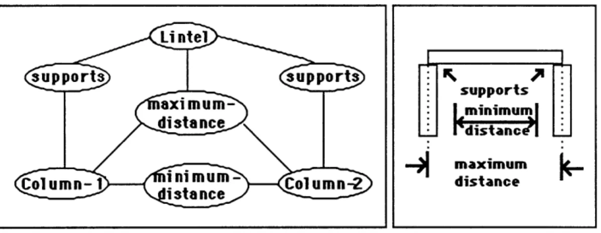
In the previous section we saw that after the three initial constraints were given, the machine inferred a new constraint, a maximum distance constraint between the two columns (Section 3.1, Figure 3.3). (We discuss in Chapter 6 how the program makes such inferences). Figure 3.10a below shows the description after the inferred constraint is added. Figure 3.10b shows the form of the configuration with the new constraint annotated.
Li ntel supports supports supports xminimum distance Idistancel -n m maximum
Col umn-1I inimum- Column-2 distance
"Arch" description with deduced constraint Figure 3.10a, b
Now let's look at the description one level deeper in detail than in Figures 3.9 and
3.10. We see that both elements and relations in Figure 3.10 are packages of more primitive
constraints and variables. That is, each of the elements "Column-1", "Column-2", and "Lintel", and each of the relations "supports", and "minimum-distance" in Figure 3.9 stands for a package of constraints and/or attribute variables, the definitions of which have been previously put in by a designer. Packages are indicated in the diagrams as ellipses. Each package has a name and may contain constraints and variables.
We now look more closely at the package of variables that describes the lintel. To keep matters uncomplicated we shall treat the lintel here as a simple element, that is, it has no smaller parts. (In chapter 4 we shall discuss configurations of elements). Figure 3.11 a shows the
Use of the Constraint Explorer
relevant variables in the lintel package. These describe the lintel's qualities, including the positions of its edges: left, right, top, and bottom, and its dimensions: length and height. Each edge may also be described by a package of variables, but here we shall not be looking in that close detail. Therefore in the diagram we need not draw the ellipses around names of edges.
Figure 3.11 a Attribute variables inside the Lintel package.
Figure 3.1lb shows the relationships between several variables inside the lintel package. The lintel's length is the distance between its left and right edges. This relation is entirely inside or local to the lintel package; all variables related by the distance relation are contained in the lintel package.
Figure 3.1 1b: Attribute variables and constraints inside the lintel package.
Like the lintel, each "supports" relation in Figure 3.9 is a package of more primitive components. The "supports" constraint relates two elements, in this case, a column and a lintel
Use of the Constraint Explorer
(see figure 3.12a). The supports constraint may apply between any elements that have the neccessary attributes for the description, that is, the supported element must have variables representing the left, right, and bottom edges, and the supporting elements must have center and top edge variables (figure 3.12b).
(supported element) LINTEL right
right left
left bottom
Lintel bottom
between
supports supports supports
to p
Col umn- I center top
(supporting element) center
COLUMN- I
The supports relation in detail. Figures 3.12a, b, c
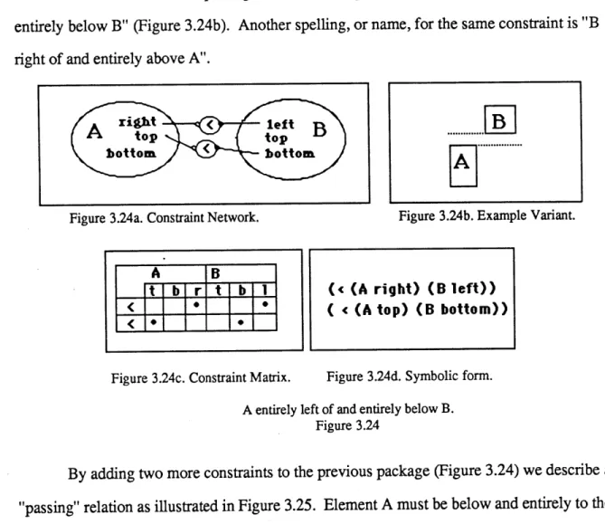
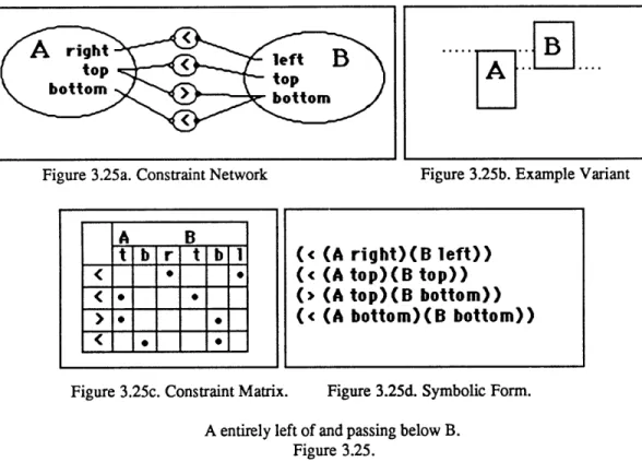
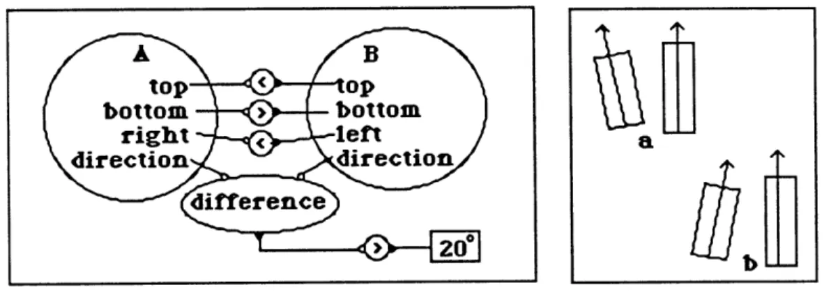
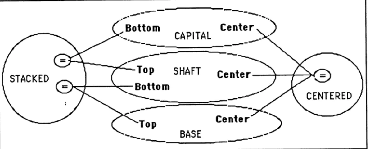
Figures 3.12c illustrates the constraint explorer's expanded description of the "supports" package as position relations between variables of the two elements. "Supports" contains two simpler position constraints. The first constraint is that the top edge of the
supporting element (the column) and the bottom edge of the supported element (the lintel) must be at the same height, or EQUAL in position. The second constraint is that the center of the supporting element must lie BETWEEN the right and left edges of the supported one. Figure
3.12d shows that the "BETWEEN" constraint, like "SUPPORTS", is a package of more
primitive constraints "<", and ">". Here, these constraints may be read "left of, and "right
of'.
Use of the Constraint Explorer
Opening up the "BETWEEN" package inside "SUPPORTS" Figure 3.12d.
We are now ready to expand the simple model shown in figure 3.10. Figure 3.13 shows how the constraint explorer expands both the element and the constraint packages. Column and Lintel descriptions each have variables representing their edges, the Lintel also has a length variable, and each Column has a variable representing its center. The "supports" relation is expanded into more primitive position relations as in Figure 3.12c and 3.12d, and the "minimum-distance" and "maximum-distance" packages are opened up to reveal a distance computation and an inequality constraint.
botto m
center
Behind the Scenes
Use of the Constraint Explorer
Expanded description of the arch. Figure 3.13
On the basis of these constraint descriptions, the constraint explorer can perform various calculations. If we give the positions of the two columns, then the machine will
calculate the effects on the lintel's length. If instead we give the position of one column and the lintel length , then the explorer calculates the other column's position. (In section 4.3 we shall
see thafunder some conditions, the direction of calculation, or propagation of effects, may be restricted). Thus the constraint explorer can express each constraint from the different points of view of each of the variables it constrains. The first support constraint, for example, can be seen as both "column-1 supports lintel" and "lintel is supported-by column-l".
We next make two settings in the design. Figure 3.14a shows the description network of Figure 3.13 with a new setting injected: we set the position of the center of column- 1 to X. Assume X names a previously defined position.
Use of the Constraint Explorer
Injecting a new value into the network:
>> set (column-1 center) X.
Figure 3.14a
As the new setting is entered, the effects propagate through the design. Figure 3.14a shows the state of the design description after column-1 has been positioned and effects have
stopped propagating. Heavy lines trace the effect of the setting outward from its injection into the network. Any new constraints on the value of variables are recorded on the diagram in
place of the variable names. (Recall that"<" , and ">" mean "left of ", and "right of'
respectively.)
Fixing the center of column-1 at position X has immediate effects on two other
variables. The left edge of the lintel must be left of X, the right edge of the lintel must be right of X. Notice that although two variables related by the lintel's length-left-right distance constraint have received effects of the new setting (lintel left and lintel right), still no changes can be computed for the lintel's length. The lintel's length is computed by the distance between
Use of the Constraint Explorer
its right and left edges, and all that is known about the positions of the edges is that one of them is to the left of position X and the other is to the right. As yet, nothing can be said about the distance between the edges.
After setting the lintel's length, the design state looks like Figure 3.14b.
Figure 3.14b
The new value for Lintel length, together with the positioning of column-i's center affects one more variable, the center of column-2. The length of the lintel and the center of column-1 are given, and the explorer now limits the center of column-2 to be within one lintel-length of the center of column- 1. That is,
(Column-2 center) < X + 12.
Use of the Constraint Explorer
Notice that the effects of the change did not reach the tops or bottoms of any elements. Nor is the left edge of column-1 or right edge of column-2 affected. The center of each column is defined as being midway between its left and right edges. These constraints are illustrated in Figure 3.15. The center is equidistant from the left and right edges, and the distance between the edges is equal to the column's width. As we have not specified the column width, no effects of setting the center reach the position of the edges.
center 1/2 left right distance width Figure 3.15
Notice also that had we chosen to first dimension the lintel, we would not observe any effects until we also had positioned one of the columns. The Lintel length is bound only by two constraints, the internal "lintel dimension" constraint that relates the lintel's left, right, and length variables, and the "maximum distance" constraint between the columns. Each of these requires another variable value in order to compute and transmit a change. Had we positioned column-2 instead of placing column-1, then a different though symmetric set of calculations would have occurred, as the reader may confirm.
So far the constraints in this model do not fix the values of variables; they only limit them. Even when we set the position of column-1 and the length of the lintel, the position of column-2 was still free to vary within a range of 4' to 12' from column-1. To determine the positions of elements, we might constrain the distance between the column centers to equal