HAL Id: cea-02339338
https://hal-cea.archives-ouvertes.fr/cea-02339338
Submitted on 15 Dec 2019
HAL is a multi-disciplinary open access
archive for the deposit and dissemination of
sci-entific research documents, whether they are
pub-lished or not. The documents may come from
teaching and research institutions in France or
abroad, or from public or private research centers.
L’archive ouverte pluridisciplinaire HAL, est
destinée au dépôt et à la diffusion de documents
scientifiques de niveau recherche, publiés ou non,
émanant des établissements d’enseignement et de
recherche français ou étrangers, des laboratoires
publics ou privés.
CATHARE3 transient analysis of an innovative Power
Conversion System based on the Brayton cycle modelled
with real gas Equations Of State
J.-B. Droin, V. Pascal, P. Gauthe, F. Bertrand, G. Mauger
To cite this version:
J.-B. Droin, V. Pascal, P. Gauthe, F. Bertrand, G. Mauger. CATHARE3 transient analysis of an
innovative Power Conversion System based on the Brayton cycle modelled with real gas Equations Of
State. ICAPP, Apr 2018, Charlotte, United States. �cea-02339338�
CATHARE3 transient analysis of an innovative Power Conversion System based on the Brayton
cycle modelled with real gas Equations Of State
Jean-Baptiste DROIN1, Vincent PASCAL1, Paul GAUTHE1, Frédéric BERTRAND1, Gédéon MAUGER2
1
: CEA, DEN, DER, F-13108 Saint-Paul-lez-Durance, France 2: CEA, DEN, DM2S, F-91191 Gif-sur-Yvette, France
Email: jean-baptiste.droin@cea.fr
ABSTRACT
The present paper is dedicated to preliminary studies of the transient behavior of the ASTRID (Advanced Sodium Technological Reactor for Industrial Demonstration) demonstrator developed in France by CEA and its industrial partners. ASTRID is foreseen to demonstrate the progress made in Sodium Fast Reactor (SFR) technologies at an industrial scale by qualifying innovative options, some of which still remain open in the areas requiring improvements, especially safety and operability. Among the innovative options, a gas Power Conversion System (PCS) based on the Brayton thermodynamical cycle is currently considered. The main objective of such a PCS consists in physically avoiding the possibility of a sodium/water reaction with the secondary circuit.
To assess the transient behavior of such a PCS when facing incident/accident sequences, previous calculations were carried out using the CATHARE 2 thermal-hydraulics code, which considers by default the working gas as an ideal gas in its Equations Of States (EOS). However, this approximation is no longer valid for the high pressure levels of this Brayton cycle. This paper thus describes new calculations performed considering real gas EOS that are now available in CATHARE 3. The simulation of the nominal PCS working point is shown to be much more accurate than in previous CATHARE 2 calculations as the discrepancy regarding the theoretical working point is less than 1°C for the gas temperature and less than 1 % for all the components power levels (compressors, heat exchangers and turbines). The impact of this new real gas hypothesis in CATHARE 3 on an unprotected transient simulation has also been investigated on a loss of power supply case. For short time scales, the impact of such an hypothesis is demonstrated to be very low. However, an improvement of the heat extraction with the real gas option should enhance the natural convection in the primary circuit to the longer term.
1- INTRODUCTION
As briefly recalled in the overview of the ASTRID reactor objectives and design (section 2-), the main goal of the innovative PCS design based on the Brayton cycle consists in physically avoiding the possibility of a sodium/water reaction at the interface between the secondary and the ternary circuit. This innovative architecture indeed involves nitrogen at 180 bars (at the inlet turbine) as a working gas, instead of a steam/water system. The thermalhydraulic system code CATHARE 3 now includes new modelling possibilities that enable the calculation of such a real gas flow using the real gas equation of state instead of the ideal gas approximation. This new feature is described in section 3-, which also presents the ASTRID input deck content. The influence of this new modelling has to be assessed. The impact of the real/ideal gas option on the main simulation features (thermal loadings, natural convection, etc.) is thus presented in this paper. This work has been carried out for the nominal state (section 4-) and for a loss of power supply transient combined to the failure of the reactor scram (section 5-).
2- OVERVIEW OF THE ASTRID REACTOR DESIGN
ASTRID, standing for Advanced Sodium Technological Reactor for Industrial Demonstration, is being designed to fulfil the Gen IV criteria in terms of safety, sustainability, economy and proliferation resistance [1]. This demonstrator consists in a 1500 MWth (600 MWe) SFR integrated pool type reactor [2]. The main objective of ASTRID is to test advanced technologies at an industrial scale in dedicated areas (in particular safety, operability, in-service inspection and repair). ASTRID is also designed to demonstrate the feasibility of waste transmutation in order to reduce volume and lifetime of ultimate waste. Many options have been investigated to improve safety during the pre-conceptual and conceptual design periods (carried out between 2010 and 2015) on the following points:
- prevention of core degradation and mitigation of its effects (innovative CFV core design characterized by a low total voiding effect,
presence of complementary safety devices dedicated to prevention and mitigation such as corium relocation ducts and core catcher [3]); - elimination of the possibility of sodium/water
reaction at the interface between secondary loops and ternary circuit (investigation on the feasibility of a gas power conversion system based on the Brayton thermodynamical cycle, instead of a water/steam system);
- enhancement of the reliability of the decay heat removal system (DHR).
2.1- CFV core concept
The version of the core considered for the studies presented in this paper is shown in Figure 1. This axial heterogeneous core has been designed to increase the time before boiling in case of unprotected transients [4] and also to reduce the probability and the severity of the primary power excursion that may occur in case of accidents [5]. The low void worth effect of the CFV core results mainly from the presence of a sodium plenum above the fissile zones [6] combined to the presence of a fertile plate in the inner core (Figure 1). Moreover, the height of the outer fissile zone enables the void reactivity effect to be decreased due to a neutron leak enhancement. All these effects lead to a reactivity decrease when the upper part of the core (plenum in particular) undergoes a sodium thermal expansion or sodium boiling.
Figure 1 – General CFV core geometry (vertical cut) [6] 2.2- Primary and secondary circuits
The ASTRID pool type primary circuit includes 3 primary pumps and 4 intermediate heat exchangers (IHX) immersed in the reactor vessel (Figure 2). Each of the 4 secondary loops delivers a fourth of the core power (375 MWth) to sodium/gas heat exchangers (SGHX). The currently chosen system for these secondary circuits involves electro-magnetic pumps. Finally, an argon
covered expansion vessel is foreseen in order to protect the secondary loop against an accidental pressure wave. The main features of the reactor operating point are provided in Table 1 for the primary and secondary circuits.
Figure 2 - Primary system arrangment for ASTRID
Primary Circuit
Core flow rate (kg/s) 7900 Fraction of the flow for vessel cooling
(kg/s)
600 Primary flow rate (kg/s) 8500 Core inlet/outlet temperature (°C) 400/550 Core inlet/outlet pressure (bar) 4.5/1.9
Secondary Circuit
Secondary flow rate (kg/s) 6370 IHX inlet/outlet temperature (°C) 345/530 Pump inlet/outlet pressure (bar) 1.9/7.1
Table 1 - Nominal operating point for the secondary and primary ASTRID circuits [7]
2.3- Gas Power Conversion System (PCS)
The choice of nitrogen as working gas has been made by taking into account heat transfer, compression work, pressure level and ease of operation. Consideration of all these criteria led to nitrogen at 180 bars (turbine inlet) as the reference coolant. A Brayton cycle, which has never been tested in a sodium reactor but already investigated for High Temperature Reactors (HTR) [8], has been chosen [9].
The PCS architecture considered in this study, using pure nitrogen as a working gas, is illustrated in Figure 3. Its design is made of two shaft-lines, each one including two symmetric turbines arranged in parallel, a low pressure compressor and a high pressure compressor plus an
alternator [10]. The efficiency of the whole gas compression is improved by means of a precooler and an intercooler separating the two compression stages; these heat exchangers (HX) are cooled by the water heat sink of the reactor. Finally, a so-called recuperator HX pre-heats the gas flow before entering the SGHX and cools it before entering the pre-cooler. The net efficiency of the reactor considering this PCS option is about 37.4% according to preliminary assessments [11]. For mechanical and manufacturing reasons, a multiple pipe design has been adopted in parallel (to limit the gas velocity in the pipes and to limit the maximum pipe diameter at about 1 m). The main boundary conditions for the thermodynamic gas cycle calculations are the following [9] [12]:
- Thermal power delivered to the gas cycle (2 GTA): 1502 MWth;
- Sodium gas heat exchanger outlet temperature: 515°C;
- Sodium gas heat exchanger outlet pressure: 180 bar;
- Sodium gas heat exchanger inlet temperature: 310°C;
- Cooler outlet temperature: 27°C.
Figure 3 – Reference ASTRID Brayton cycle [12]
As illustrated in Figure 4, for regulation related reasons during normal operation and incidental or accidental situations, a few bypass lines are also included in the PCS design. In this paper, only the turbine bypass line (red line in Figure 4) is used. In the section dedicated to a loss of power supply transient analysis (5-), the opening of this bypass valve indeed enables to stop the TM rotating speed by reducing the outlet/inlet pressure ratio (which is directly related to the bypass valve opening ratio).
Figure 4 - Scheme of several bypasses on the reference Brayton cycle [12]
3- BRIEF PRESENTATION OF THE ASTRID CATHARE 3 MODELLING
The CATHARE system code is the outcome of more than 30 years of joint development effort by CEA and by its industrial partners. It was originally devoted to best estimate calculations of thermal hydraulic transients in water-cooled reactors. The two-fluid model with non-condensable gases transport equations, with light water as the main fluid, was extended to other new generation reactors such as SFR. The CATHARE code is now a multi-purpose multi-reactor concept 6-equations thermalhydraulic system code.
To assess the performance of ASTRID in normal operation and its behavior when facing incidental or accidental transients, previous safety and operability calculations were carried out using CATHARE 2 [13]. However, the working gas in the PCS is considered by default as ideal in this version of the code. This hypothesis not only impacts the thermo-physical properties calculation for the fluid, but also the TM performances modelling which is ideal gas dependent in this version of the code. This is why new calculations are carried out with CATHARE 3, which enables considering a real gas instead of an ideal one in simulations. The new modelling possibilities associated with such a real gas in CATHARE 3 are briefly described below, and a description of the main reactor modelling content is then proposed.
3.1- New real gas modelling possibilities available in CATHARE 3
Real gas Equation Of State
In CATHARE 2, nitrogen was considered as an ideal and non-condensable gas, whose thermophysical properties only depend on the fluid temperature. For high pressure levels, this approximation may lead to some discrepancies (assessed in section 4- for the nominal state calculation). This is why a call to the REFPROP table [14] is possible in CATHARE 3 in order to compute the real gas properties.
Real gas turbomachinery modelling
In both CATHARE 2 and CATHARE 3, the TM efficiency is deduced from two reduced values, respectively assessing the flow rate and the shaft rotating velocity. However, in CATHARE 2, these two values are calculated considering the fluid as an ideal gas, which is no more consistent if the real gas properties are considered as newly possible with CATHARE 3. This is why a recently implemented TM modelling uses the speed
of sound in the fluid (instead of its temperature like it was done in CATHARE 2) to adequately compute these reduced values without using the ideal gas law.
3.2- Input deck content Core
The whole 288 core sub-assemblies (SAs) are represented by 31 weighted 1-D axial channels. The following neutronic effects are modelled: Doppler effect, sodium density, cladding expansion, fuel expansion, hexcan (HC) expansion, diagrid expansion and finally the reactivity feedback resulting from the relative position of the control rods within the core. All these reactivity coefficients are included in the point kinetics of neutron physics module of CATHARE including 8 groups of delayed neutrons and 4 groups of fission products to model the decay heat. Finally, the Complementary Safety Devices that are currently considered for prevention purpose are also modelled in the input deck.
Primary and secondary circuits
The core channels, the IHX, the fraction of primary flow cooling the vessel and the inlet/outlet region of the pumps are modelled thanks to 1-D CATHARE 3 axial elements. The flow distribution within the cold and hot collectors is modelled thanks to several dedicated 0-D volumes. The secondary circuit is modelled with 4 distinct 1-D elements, each one representing one secondary loop including an electromagnetic pump. Each of these loops is connected to the primary circuit via one IHX and to the PCS via one equivalent SGHE representing a pair of HXs.
Power Conversion System
The PCS system is fully modelled in the CATHARE 3 input deck. Each of the HXs (precooler, intercooler, recuperator) is modelled thanks to a 1-D CATHARE 3 axial element, such as the turbine bypass line. The parameters of the heat transfer correlation (Dittus-Boelter form) for plate type Na/gas exchangers (SGHE) used in CATHARE 3 have been derived from CFD calculations [10]. The rotating mass equation is solved on the TM shaft including the turbine, the compressors and the resisting torque of the alternator when it is connected to the grid. Comprehensive TM performance maps are provided as an input data.
4- NOMINAL STATE CALCULATIONS 4.1- Calculations assumptions
The main goal of the study presented in this paper is to assess the impact of taking into account real gas EOS
instead of ideal gas ones on simulation results, for the nominal state as for transient situations. Thus, two kinds of calculation results are presented in the following sections, respectively referring to:
- a so-called “ideal gas simulation”; - a so-called “real gas simulation”.
For the ideal gas simulation, the new CATHARE 3 modelling possibilities related to real gas (described in section 3.1-) are not taken into account whereas they are considered in the real gas simulation.
4.2- Calculations results
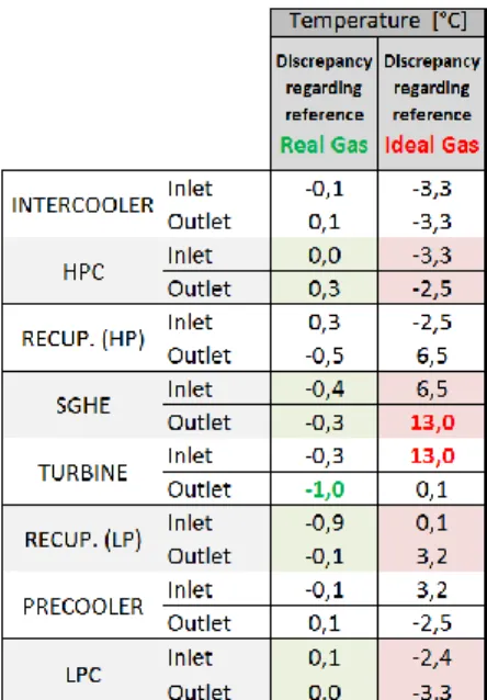
Discrepancies between the simulations results and the reference ones (assessed with a tool dedicated to thermodynamics cycle analyses) are listed hereafter for power of the PCS components (HX, TM), and temperature/pressure in the flow along of the thermodynamical cycle (Table 2, Table 3 and Table 4). Let’s note that, for the study presented in this paper, no corrective factor is taken into account in the CATHARE 3 input deck (whether the gas is ideal or real) as it was done with CATHARE 2 to compensate discrepancies due to the ideal gas law approximation.
Table 2 – Comparison between the PCS components power calculated with CATHARE 3 with real or ideal gas option
Table 3 – Comparison between gas temperatures calculated with CATHARE 3 with real or ideal gas option
Table 4 – Comparison between the PCS pressure calculated with CATHARE 3 with real or ideal gas option
Regarding the reference results, the power of the different components of the cycle (TM and HX) calculated in the real gas simulation is much more accurate than with the ideal gas EOS. The maximum discrepancy is indeed negligible in the first case (only 0.4%) regarding the 11% discrepancy in the second case (Table 2). The same conclusions can be drawn from the temperature results table: the maximum discrepancy when considering the real gas option is only 1°C, that is to say much lower than the 12°C when considering the ideal gas simulation (Table 3). Even for the calculated pressure levels (Table
4), the discrepancy reaches 2.1 bars for the real gas case instead of 3.4 bars in the ideal gas simulation. All in all, taking into account the real gas option in CATHARE 3 clearly provides more accurate results for the nominal state calculation than considering the ideal gas modelling.
5- TRANSIENT CALCULATIONS 5.1- Calculations assumptions
As for the nominal state calculations, the presented results respectively refer to a real and to an ideal gas simulation. However, to focus on the influence of ideal or real gas modelling on transient simulations, the choice has been made to start from an equivalent nominal state for both simulations by implementing corrective factors in the ideal gas case. These corrective factors, that are dealing with the HX exchange section and on the TM nominal performance values, enable for instance to reduce the maximal discrepancy on pressure levels from 3.4 bars to 0.4 bars only.
5.2- Scenario
The considered transient results from the total and unprotected loss of electrical supply: there is no back-up flow rate delivered by means of emergency electrical supply. The reactor trip is actuated at t=0s. The primary pumps run-down is then governed by their mechanical inertia. In the secondary loops, the electromagnetic pumps power supply is instantaneously turned off. The water feeding of the coolers in the PCS is no more available as well. At t=1s (assumption), the valve of the turbine bypass automatically opens from 0% to 100% in 0.5s (assumption) to counteract the turbomachine runaway and to limit the shaft overspeed. If the respective thresholds of the considered Complementary Safety Devices are reached, the corresponding anti-reactivity is automatically inserted into the core to shut the power off. Note that the dedicated DHR loops plugged on the primary circuit of the reactor are not used during this penalized transient.
5.3- Results Power Conversion System
In the PCS, the reactor trip that occurs at t=0s results in the annulation of the resisting torque on the shaft related to the alternator grid connection. This imbalance on the shaft explains its sudden rotational overspeed (~+10%, cf. Figure 5), which is quickly limited by the turbine bypass valve opening at t=1s. As this bypass is a link between a high pressure pipe (~180 bar) and a low pressure one (~60 bar), its opening leads to a drastic rise of the gas mass flow rate in the SGHE (+60%, cf. Figure 6). Then, the pressure equalization between the inlet and the outlet
of the turbine leads to a slow decrease of the gas mass flow rate in the whole circuit, until its annulation after 100s.
Figure 5 – TM rotational speed evolution during an unprotected total loss of electrical supply (CATHARE 3, ideal and real gas options)
Figure 6 – Gas flow rate evolution in the SGHE during an unprotected total loss of electrical supply (CATHARE 3, ideal and real gas options)
Secondary circuit
The drastic increase of the PCS gas mass flow rate in the SGHE at the beginning of the transient is not sufficient to increase the power extracted in the SGHE since the reduction of the sodium mass flow rate in the secondary loops starts 1s earlier and is very fast due to the electromagnetic nature of the secondary pumps. At t=0s, the secondary mass flow rate has indeed already decreased by 25% (Figure 7) whereas the PCS mass flow rate is still around its nominal value because of the
1s-delayed turbine bypass opening. Consequently, the power extracted from the secondary loops via the SGHE decreases monotonically down to 20% of its nominal value at t=20s (Figure 8). As this decrease is slower that the secondary mass flow rate reduction, the transient firstly leads to a cold loading in the cold leg of the secondary circuits. At the SGHE outlet, the sodium temperature then decreases down to 320°C at t=30s, cf. Figure 9. For natural convection reasons, the secondary mass flow rate is quickly stabilized at 12% of its nominal value whereas the SGHE power is still slowly decreases because of the PCS mass flow rate reduction. The cold loading in the secondary cold leg loop is thus followed by a hot loading in the longer term.
Figure 7 – Secondary mass flow rate evolution during an unprotected total loss of electrical supply (CATHARE 3, ideal and real gas options)
Figure 8 – Evolution of the power exchanged in the SGHE during an unprotected total loss of electrical supply (CATHARE 3, ideal and real gas options)
Figure 9 – Sodium temperature evolution at the SGHE outlet during an unprotected total loss of electrical supply (CATHARE 3, ideal and real gas options)
Primary circuit
The decrease of the primary mass flow rate illustrated in Figure 10 associated with the reduction of the power extraction in the IHX firstly results in the heating-up of the sodium at the core outlet. Therefore and due to neutronic feedback effects, the total core power decreases in the first seconds of the transient, cf. Figure 11. At t=9s, the primary mass flow rate reaches the mass flow rate threshold leading to the drop of the hydraulic triggered complementary safety device into the core, and so to the shut-down of the neutron chain reaction. The core power evolution then corresponds to the residual power delivered by the fuel assemblies.
Figure 10 – Primary mass flow rate evolution during an unprotected total loss of electrical supply (CATHARE 3, ideal and real gas options)
Figure 11 – Core power evolution during an unprotected total loss of electrical supply (CATHARE 3, ideal and real gas options)
5.4- Impact of the gas properties calculation modelling (real vs ideal)
As it can be deduced from the results presented in section 5.3-, the two simulations provide rather close trends: the impact of the gas modelling option is quite weak. In the PCS, the shaft overspeed computed is +10.8% for the real gas option and +9.7% for ideal gas one. After the opening of the bypass valve, the decrease of the gas mass flow rate and of the TM speed is a bit slower with the real gas option, enhancing the power extraction from the secondary circuits (~+5MW at 100s). As a consequence, the sodium temperature in the cold leg of secondary loop appears to be significantly lower for the real gas option (~-10°C), thus improving a little the setting up of natural convection in the secondary loops (+1% on the secondary mass flow rate at t=100s). A preliminary study dedicated to a longer term simulation indicates that after 500s, this discrepancy increases: the secondary mass flow rate becomes 6% higher for the real gas option than for the ideal case.
In the primary circuit, the influence of the ideal/real gas modelling on the natural convection mass flow rate is negligible at short time scales (maximum discrepancy lower than 0.3% before 100s). The same conclusion can be drawn for the neutron power delivered in the fuel1. At 500s, the preliminary longer term study however indicates that the slightly improved heat extraction with the real gas option enhances the presence of a cold spot in the IHX, thus slightly increasing natural convection in the primary circuit (~+2% at t=500s). Such consequences on long time scales still should be investigated in further studies.
1
Locally, the maximum discrepancy reaches 5% but it is only related to a time lag of one time step at the hydraulic triggered complementary safety device drop instant.
6- CONCLUSIONS AND PROSPECTS
ASTRID is a demonstrator developed in France by CEA and its industrial partners; it is foreseen to demonstrate the progress made in Sodium Fast Reactor (SFR) technologies at an industrial scale. For this purpose, innovative options are currently considered, especially dealing with safety and operability. Among them, a gas Power Conversion System (PCS) based on the Brayton cycle consists in physically avoiding the possibility of a sodium/water reaction at the interface with the secondary loops. To assess the overall efficiency of such a PCS and its behavior when facing severe accident sequences, previous calculations were carried out using the CATHARE 2 thermal-hydraulics code, which considers by default the working gas as an ideal gas. However, this approximation is no longer valid for the high pressure levels of the Brayton cycle (180 bars at the turbine inlet). New calculations were thus performed considering real gas EOS that are now available in CATHARE 3.
The new simulation of the nominal PCS working point is shown to be much more accurate than in previous calculation considering an ideal gas. The maximal discrepancy regarding the reference working point is indeed less than 1°C for the gas temperature and less than 1 % for all the components power levels (compressors, heat exchangers and turbines). Also, the influence of the real/ideal gas modelling has been preliminary assessed on a transient resulting from a total and unprotected loss of electrical supply. The first main conclusion is that in case of such a reactor trip, the overall reactor behavior is characterized by the same phenomenology whether the gas is considered real or ideal. In both cases, the opening of the turbine bypass valve enables the limitation of the TM overspeed at around +10%, and natural convection in the secondary loops is taking place as a function of the heat extracted in the PCS. However, a slightly improved heat extraction in the Sodium Gas Heat Exchanger is observed in the real gas simulation (+5MW). For short time scales, it has no significant impact, especially regarding the sodium evolution in the primary circuit, but it may enhance natural convection in both primary and secondary circuits to the longer term. Several studies aiming at investigating this long term behavior are being prospected.
ACKNOWLEDGMENTS
The authors would like to thank their colleagues of AREVA NP for their work on the CATHARE input deck, as well as the sodium fast reactor R&D project and the Gen IV program of the Nuclear Energy Division of CEA that have supported this work.
REFERENCES
[1] «A technology roadmap for Generation IV Nuclear Energy Systems,» US DOE and the Generation IV International Forum, December 2002.
[2] P. Le Coz et al., «The ASTRID Project: status and future prospects,» FR13, Paper CN 199-261, Paris, France 4-7 March 2013.
[3] F. Bertrand et al., «Status of severe accident studies at the end of the conceptual design of ASTRID: Feedback on mitigation features,» Nuclear
Engineering and Design, vol. 326, p. 55–64, 2018.
[4] M. Chenaud et al., «Status of ASTRID core design studies at the end of predesign phase 1,» Nuclear
Engineering and Design, vol. 45, n° 16, 2013.
[5] D. Lemasson et al., «Simulation with SAS-SFR of a ULOF transient on ASTRID-like core and analysis of molten clad relocation dynamics in heterogeneous subassemblies with SAS-SFR,» ICAPP 2014, Charlotte, USA, April 6-9 2014.
[6] P. Sciora et al., «Low void effect core design applied on 2400 MWth SFR reactor,» ICAPP, Nice, France, May 2–6 2011.
[7] F. Bertrand et al., «Transient behavior of ASTRID with a gas power conversion system,» Nuclear
Engineering and Design, vol. 308, pp. 20-29, 2016.
[8] F. Bertrand et al., «Synthesis of the safety studies carried out on the GFR2400,» Nuclear Engineering
and Design, vol. 253, p. 161– 182, 2012.
[9] D. Plancq et al., «Progress in the ASTRID Gas Power Conversion System development,» FR17, Yekaterinburg, Russia, June 26-29 2017. [10] L. Cachon et al., «Innovative power conversion
system for the French SFR,» ICAPP, Chicago, USA, June 24–28 2012.
[11] G. Laffont et al., «ASTRID power conversion system: assessment on steam and gas options,»
FR13, Paris, France, 4–7 March 2013.
[12] D. Barbier et al., «Main operation procedures for ASTRID gas power conversion system,» FR17, Yekaterinburg, Russia, June 26-29 2017.
[13] G. Geffraye et al., «CATHARE 2 V2.5_2: a single version for various applications.,» NURETH-13, Kanazawa City, Ishikawa Prefecture, Japan, September 27–October 2 2009.
[14] E. Lemmon et al., «NIST Standard Reference Database 23: Reference Fluid Thermodynamic and Transport Properties-REFPROP, Version 9.1,» National Institute of Standards and Technology, Standard Reference Data Program, Gaithersburg, 2013.
![Figure 1 – General CFV core geometry (vertical cut) [6]](https://thumb-eu.123doks.com/thumbv2/123doknet/12987860.378944/3.918.548.780.233.457/figure-general-cfv-core-geometry-vertical-cut.webp)
![Figure 4 - Scheme of several bypasses on the reference Brayton cycle [12]](https://thumb-eu.123doks.com/thumbv2/123doknet/12987860.378944/4.918.84.426.858.1026/figure-scheme-bypasses-reference-brayton-cycle.webp)