HAL Id: cea-02183828
https://hal-cea.archives-ouvertes.fr/cea-02183828
Submitted on 15 Jul 2019
HAL is a multi-disciplinary open access
archive for the deposit and dissemination of
sci-entific research documents, whether they are
pub-lished or not. The documents may come from
teaching and research institutions in France or
abroad, or from public or private research centers.
L’archive ouverte pluridisciplinaire HAL, est
destinée au dépôt et à la diffusion de documents
scientifiques de niveau recherche, publiés ou non,
émanant des établissements d’enseignement et de
recherche français ou étrangers, des laboratoires
publics ou privés.
A Comparison of the V2X Communication Systems:
ITS-G5 and C-V2X
Valérian Mannoni, Vincent Berg, Stefania Sesia, Eric Perraud
To cite this version:
Valérian Mannoni, Vincent Berg, Stefania Sesia, Eric Perraud. A Comparison of the V2X
Commu-nication Systems: ITS-G5 and C-V2X. IEEE Vehicular Technology Conference (VTC) Spring 2019,
Apr 2019, Kuala-Lumpur, Malaysia. �cea-02183828�
A Comparison of the V2X Communication
Systems: ITS-G5 and C-V2X
Valerian Mannoni
1, Vincent Berg
1, Stefania Sesia
2and Eric Perraud
21 CEA, LETI, Minatec Campus, 17 rue des Martyrs, 38054 Grenoble, France 2Renault Software Labs, 2600 Route des Cretes, 06560 Valbonne, France
{valerian.mannoni, vincent.berg}@cea.fr, {stefania.sesia, eric.perraud}@renault.com
Abstract—Vehicle to vehicle/infrastructure communication sys-tems have a significant role to play in optimizing road traffic and improving road safety. In this context, two standards have emerged, namely ITS-G5 (IEEE 802.11p) and C-V2X (3GPP Release 14). The objective of this article is to compare both standards by evaluating the performance of both physical layers and associated MAC layers. The physical layer performance of a single link is first evaluated and used to derive performance in a loaded network where each user is scheduled by their respective MAC layer. Performance evaluation shows an advantage for the C-V2X for low levels of vehicles density while when the congestion increases the performance gap reduces until ITS-G5 eventually outperforms C-V2X. Finally, latency was also assessed for both communication systems.
Index Terms—V2X communication, ITS-G5, C-V2X, Physical Layer, MAC layer, CSMA/CA, Sensing-Based Semi-Persistent Scheduling, Performance Evaluation
I. INTRODUCTION
Vehicle-to-vehicle (V2V) and vehicle-to-infrastructure (V2I) communications, referred as vehicle-to-everything (V2X), is a wireless technology aimed at enabling data exchanges between a vehicle and its surroundings. Two main vehicular communication standards using the specially allocated 5.9GHz unlicensed band have emerged in recent years: On one hand the Dedicated Short-Range Communications (DSRC) protocol developed in the US [1] and the Intelligent Transportation System (ITS)-G5 protocol developed by the European Telecommunications Standards Institute (ETSI) [2]. These standards are based on the IEEE 802.11p access layer developed for vehicular networks. A competing alternative has recently emerged with the introduction of Proximity Services (ProSe) in 3GPP Long-Term Evolution (LTE) Release 14 and evolved in Release 15, notably the so called modes 3 and 4, based on the interface ‘PC5’ [3] without or with any involvement of the eNB (respectively). PC5 interface have been designed to satisfy bounded low latency requirements and accommodate a given levels of density of vehicles for C-V2X communications combined with the support of high speed. Although the vehicular protocol stack (DSRC and ITS-G5) has been defined with IEEE 802.11p in mind, it can be adapted the C-V2X access layer. Optimization of the protocol stack to PC5 is currently under discussion in ETSI ITS working group. In this paper, we will focus on communication mode 4 only. While IEEE 802.11p is a rather mature technology, whose capability has been tested in a large number of testbeds, C-V2X is more recent (first trials have been performed at the end of 2017 [4]) and comparisons between the technologies are not widely available. In earlier publications [5] [6], system level results for limited scenarios have been considered, without considering feasible configurations taking
TABLE I
IEEE 802.11P VERSUSC-V2X, PHYLAYER MAIN PARAMETERS
IEEE 802.11p C-V2X Sampling Frequency, Fe(Fe) 10MHz 15.36MHz
Tone Spacing, ∆f 156.25kHz 15kHz FFT Size, NF F T 64 1024
Symbol Duration, Ts 8µs 66.67 µs
Number of data subcarriers, Nu 48 12×RB
Cyclic Prefix Size, Ncp 16 (1.6µs) 72 (4.7µs)
Modulation QPSK QPSK / 16QAM Forward Error Correction CC TC
Coding Rate, Rc ½ from MCS
Transmit power 23dBm 23dBm
into account congestion control mechanisms which have been recently defined in ETSI and which does not necessarily allow to conclude on the overall relative performance gap between both communication systems. Moreover, the objective of this paper is to analyze both technologies not only considering the physical layer but also the MAC layer according to their operating points or allowed configurations taking into account field tests packet size statistics. The paper is structured as follows. After a presentation of the IEEE 802.11p and C-V2X standards and in particular their physical layer and MAC layer in section II, the performance evaluation is given in Section III starting with a focus of the physical layer (section III-A). The results of section III-A are then used to derive performance in a loaded network integrating a congestion model (Section III-B). Section IV concludes the document with a synthesis on the evaluation.
II. V2XCOMMUNICATION SYSTEMS
A. The IEEE 802.11p communication system
The IEEE 802.11p physical layer is an evolution of IEEE 802.11a. It uses Orthogonal Frequency Division Multiplexing (OFDM) combined with a convolutional code [7]. To provide performance under rapidly varying channels, the time domain parameters have been doubled, while the frequency domain parameters have been halved. The typical parameters are given in Table I. A description of the IEEE 802.11p physical layer can be found in [7].
The MAC layer of IEEE 802.11p is based on the Outside the Context of a Basic Service Set (OCB) operation mode, where authentication, association, and data confidentiality services are not used [7]. This OCB operation mode is then well suited for rapid broadcast of short messages and a high level of mobility.
IEEE 802.11p uses the enhanced distributed channel access (EDCA) scheme to support different levels of quality of service. EDCA is based on the basic Distributed Coordination Function (DCF). DCF is based on a Carrier Sense Multiple Access with Collision Avoidance (CSMA/CA) algorithm. The predetermined listening period is called Arbitration Interframe Space (AIFS) and depends on the type of message: 110µs for Cooperative Awareness Message (CAM), 58µs for De-centralized Event Notification Message (DENM). The backoff duration is set as an integer random value between 0 and 15 times 13µs [7].
B. The C-V2X communication system
The C-V2X physical layer is based on Single Carrier Frequency Division Multiplexing Access (SC-FDMA) and supports 10 or 20 MHz channels. Each channel is divided into sub-frames, Resource Blocks (RBs), and sub-channels. The same numerology as in LTE is considered with a 1 ms long subframe and a RB corresponding to 180 kHz (i.e. 12 sub-carriers each of 15 kHz) and 0.5 ms in time. C-V2X defines sub-channels as a group of RB pairs in the same sub-frame. Sub-channels are used to transmit data and control information. The data is transmitted in Transport Blocks (TBs) over Physical Sidelink Shared Channels (PSSCH), and the control information (MCS, RBs, ressource reservation interval) in Sidelink Control Information (SCI) messages over Physical Sidelink Control Channels (PSCCH) [8] and sent within the same sub-frame. A node that wants to transmit a TB must also transmit its associated SCI. As for LTE, the control information SCI is critical as it allows to receive and decode the transmitted TB.
TBs can be transmitted using QPSK or 16-QAM mod-ulations with a set of coding rates which are defined by the Modulation and Coding Scheme (MCS) in [8], whereas the SCIs are always transmitted using QPSK with MCS=1. Unlike IEEE 802.11p, C-V2X is based on turbo coding, except for SCI which is convolutionnaly encoded. The considered parameters are given in Table I. Compared to IEEE 802.11, C-V2X provides more flexibility in terms of configuration: occupied bandwidth, modulation and coding scheme can be selected at physical layer as well as set of parameters at MAC layer. This allows to adapt transmission according to the surrounding conditions e.g. adapting the transmission to available resources, or to the congestion level. In our simula-tions, we considered the configurations that are given in Table II which stem from a set of possible configuration according to 3GPP numerology within the ranges standardized in [8], satisfying the congestion control constraints as defined in [9] and taking into account the packet size. It should be noted that we only used a subset of the possible configurations i.e. the configurations with the highest number of RBs (wide bandwidth) and the configurations with the lowest number of RBs (narrow bandwidth).
From the MAC point of view, according to Mode 4, the vehicle follows a channel reservation procedure based on the use of Sensing-Based Semi-Persistent Scheduling (SB-SPS). This protocol exploits sensing of the medium to predict the position of the available resources as specified in [10]. A vehicle reserves the selected sub-channel(s) for a number of consecutive Reselection Counter (RC) packet transmissions. RC is randomly set between [5, 15]. After each transmission,
RC is decremented by one. When it is equal to zero, new resources have to be selected and reserved with probability (1 − P ), with P ∈ [0, 0.8]. Without loss of generality P = 0 has been considered in our simulations.
Packets can be transmitted every 20, 50 or 100 sub-frames and the SPS resources can be reserved with a variable interval which is indicated in the SCI. Thanks to this approach other vehicles can predict when resources are reserved and can select a free resource to avoid packet collisions.
In C-V2X, the reliability of the transmission can be im-proved by using HARQ retransmission. The 1 blind HARQ retransmission mechanism is based on incremental redundancy as per legacy LTE and improves range and/or reliability of transmission.
III. PERFORMANCE EVALUATION
In this section, we first present the simulation results for the physical layer considering a point-to-point link. Then, we introduce the resource scheduling and evaluate performance for loaded scenarios.
A. Physical layer performance assessment
The results in this section are mainly provided in terms of Packet Error Rate (PER) versus SNR or range for both IEEE 802.11p and C-V2X. Throughout the paper, we consider the Line of Sight Winner B1 path loss model [11], while the fast fading is based on the Extended Vehicular Model EVA as defined in [12]. Several configurations are considered in particular for C-V2X. It should be noted that in this paper we consider perfect channel estimation for both technologies. This hypothesis can be considered optimistic for 802.11p in case of highly frequency varying channels and for C-V2X in case of high mobility. However, thanks to advances in channel estimation algorithm design, we do not expect this hypothesis to change the behaviour of both technologies. Moreover, we consider perfect time and frequency synchronization.
If we consider the periodic status messages which are sent by the V2X vehicles (CAM) field tests show that inter packet distance as well as messages sizes are dynamically changing. The former is mainly dependent on the vehicle dynamics and the triggering conditions whose frequency varies between 1Hz and 10Hz. The latter mainly depends on whether the complete cybersecurity certificate is included in the message with a header from 90 Bytes to 350 Bytes when the certificate is included. Fig. 1 shows that the CAM message size ranges from 200 to 700 Bytes. Hence, in the following, we considered a packet size of 300 Bytes as the average size obtained from field tests but results are also shown for variable packet sizes. Fig. 2 gives the IEEE 802.11p link performance for message sizes from 200 Bytes to 800 Bytes and assuming a speed of 130 km/h. As expected, the results show a small difference in terms of performance, i.e. a SNR between 9.8 and 10.5 dB for a target PER of 10−2 depending on the message size. This is due to the fact that the data rate and coding rate is not dynamically changed and a fixed configuration is commonly chosen as indicated in Section II-A. When the message size is longer, slightly better performance is observed because time diversity may be exploited.
Fig. 3 shows the C-V2X performance and the impact of the choice of configuration, MCS and number of RBs, for a message of 300 Bytes. As expected, parameterization that
TABLE II
C-V2XPHYSICAL LAYER CONFIGURATIONS WITH RESULTING THROUGHPUT(SIGNALING INCLUDED) Message size in Bytes 200 300 400 500 600 700 800 Number of RB for the TB 18 36 18 27 36 48 18 48 27 48 27 48 36 48 36 48
MCS 6 3 8 6 4 3 11 4 9 5 11 6 9 7 10 8 throughput 1.6 Mb/s 2.4 Mb/s 3.2 Mb/s 4 Mb/s 4.8 Mb/s 5.6 Mb/s 6.4 Mb/s
Fig. 1. CAM message statistics.
Fig. 2. ITS-G5 PER as a function of the SNR for EVA channel and different message sizes.
uses the largest number of RBs (larger bandwidth) outperforms other configurations thanks to the possibility to exploit fre-quency diversity and to use a lower coding rate (lower MCS) compared to narrowband allocations.
Fig. 3. C-V2X PER as a function of the SNR in EVA channel for a message of 300 Bytes (2.4 Mb/s) and with different MCS
The performance with different message sizes is given in
Fig. 4 where different message sizes result in an increase in throughput and therefore in a degradation of performance. The performance when 1 retransmission is used for the three different message sizes is also illustrated. We can then observe a gain between 5.3 and 7 dB in terms of SNR thanks to the additional coding gain. This gain comes from the combination of redundancy (coding gain) and better time diversity of the propagation channel. Fig. 4 shows that the SNR varies from 5 to 10.5 dB when single transmission is considered and between −0.3 and 3.5 dB when blind retransmission is used.
Fig. 4. C-V2X PER as a function of the SNR in EVA channel for different message sizes with or without a retransmission.
Performance has been synthesized in Fig. 5. The range for a PER=10−2 as a function of the throughput with 1 or 2 transmissions and for two sets of parameterization for C-V2X:
• wide bandwidth: the maximum number of RBs for each message size (right column of Table II for a given message size)
• narrow bandwidth: the minimum number of RBs for each message size (left column)
Thus, a simulation point corresponds to a message size (i.e. a throughput) associated with a MCS. The range d is then derived from the performance in terms of PER versus SNR using a transmission power PT x of 23 dBm, a noise figure
N F of 6 dB, no antenna gain and the Winner B1 path loss model (LOS) P LW B1 with the following expression
d|PT x− P LW B1(d) = ρ (1)
with ρ the sensitivity expressed by
ρ = SN RdB+ 10 log10(B) + N + N F (2)
where B is the signal bandwidth in Hz and N the power spectral density of the thermal noise (N=-174 dBm/Hz). When there is a retransmission the data rate has been halved because in this case the message is transmitted over a period that is
twice as long, i.e. 2 TTIs. Performance is highly dependent on the MCS used for each message size, especially for narrow bandwidth configurations. The configurations using the highest number of RBs offer the best performance with or without re-transmission. We can also observe that for a given throughput, retransmission provides a limited gain on the range between 0 and 40 m. However, retransmission allows much greater ranges at lower data throughput levels. ITS-G5 performance shown in Fig. 5 use the unique MCS (QPSK, Rc = 1/2) and takes
into account the ratio between the duration of the signalling preamble with the duration of the message part (from 200 to 800 Bytes) for the throughput calculation.
Fig. 5. Range as a function of the throughput for C-V2X and 802.11p.
B. V2X performance with congestion
This section evaluates the stochastic performance of both communication systems in an environment with multiple users having to share the available spectral resource. This means evaluating the performance of the MAC layers of both systems in their resource selection process and observing their impact on performance in terms of PER, range, latency and network load. The performance of both communication systems has been evaluated by simulating their respective MAC layers, namely CSMA-CA for 802.11p and SB-SPS for C-V2X. The performance of the physical layer is integrated by considering the level of interference resulting from the scheduling gener-ated by the MAC layer. For the simulations, we considered a static disc-shaped network with a given number of vehicles depending on the network load. The performance on a single link between two vehicles located in the center of the disc-shaped network is evaluated. Hence, for each level of user density in the network and for each distance between two vehicles, we draw randomly 5000 network topologies (location of the users) that we simulated for a duration of 5 seconds. Each user of the network is scheduled by its own MAC layer like the two target users. Phenomena such as hidden nodes are hence considered.
In order to compare in a fair manner both communication systems, we consider the wider possible bandwidth config-uration for C-V2X and the lowest MCS which respects the Channel occupancy Ratio (CR) based on the Channel Busy Ratio (CBR) as explained in [9]. As a result, the configuration with 48PRBs and MCS=3 is used but for a user densities between 130 and 165 users/km2, the configuration with 36RB and MCS=4 is used and for densities between 165 and 200 users/km2, 27RB and MCS=6 is used. In the simulation,
for simplicity we consider an inter-packet distance of 100ms (transmission rate of 10Hz).
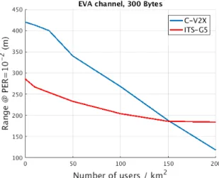
Fig. 6 presents a performance synthesis which shows the achieved range (PER=10−2) as a function of the congestion level (users/km2). We can observe that the loss in terms of
range is higher for C-V2X compared to ITS-G5. However, C-V2X has better performance (range) for the lowest user densities mainly due to the difference in data rate (4.76Mb/s for 802.11p and 2.4Mb for C-V2X). For the high user den-sities (> 150 users/km2), due to a better resource scheduler, 802.11p outperforms C-V2X. It should be noted here, that the C-V2X performance shown in Fig. 6 are based on a configuration using only one transmission, while for user densities ≤ 150 users/km2, 2 transmissions are acceptable
according to the limitations in terms of CR vs CBR and the available configurations (number of RBs) in this scenario. Thus, C-V2X performance could be further improved with the HARQ retransmission for low user density and/or by considering the Frequency Division Multiplexing scheme.
Fig. 6. Performance synthesis of C-V2X and ITS-G5: range evolution as a function of the network load.
V2X communication systems consider latency to be an im-portant performance metric as some applications (such as pre-crash sensing) require very stringent requirements. Hence, the latency is evaluated in the following. Here, ”packet” latency is defined as the time required to correctly receive the packet taking into account the time to access physical layer resources and the time to correctly receive the packet. In 802.11p, the access time to the resource depends on the CSMA-CA parameters, i.e. AIFS (110 µs), the backoff (between 0 and 195 (15 · 13) µs) and sensing threshold according to the algorithm described in [7], as well as the network load. Thus this access time will increase with the user density. However, spatial reuse is possible, i.e. users for which their sensed power is below the sensing threshold, will be able to use the same resources. In our simulations a sensing threshold of −85dBm is used.
In C-V2X, when a new resource is to be selected, the SB-SPS algorithm requires to randomly choose one resource from 20% of the candidate single-subframe resources over a selection window which can be either 20ms or 100ms. The resources are considered as available/unavailable depending on a sensing threshold (RSSI based on the last 1000 subframes); when less than 20% of the resources are available the sensing threshold is increased by 3dB.
Because of the fixed reselection window, the time to access the resources is independent of the network load and it is equal on average to 50.5 ms for a selection window of 100 ms and 10.5 ms for a selection window of 20 ms. This new selected sub-channel is then reserved for a number of consecutive Reselection Counter packet transmissions (between [5,15]).
Fig. 7 illustrates the average time required to access the resource for both standards. For 802.11p, the average time to access the resource depends on the network load and increases with the user density with latency of 207 µs for low densities to reach 10 ms only for very high user density of 3000 users/km2.
Fig. 7. Average time to access the resource as the function of the user density for ITS-G5 and C-V2X.
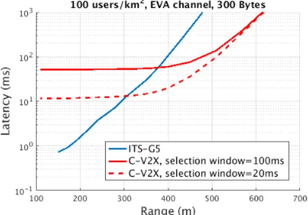
The overall latency defined here as the average time to receive one packet correctly is given in Fig. 8 for a density of 100 users/km2 for 300 Byte packets. The performance takes into account packet error probability which is dominated by additive noise and collisions when the range is increased. We can then observe that 802.11p has a much lower latency than C-V2X for lower ranges. However, the gap between both standards tends to decrease as the range of communication increases and C-V2X outperforms 802.11p for ranges above 305m for a selection window of 20 ms and 375m for 100 ms. Indeed, the high value of PER induced by larger ranges has a significant impact on the number of packets to be transmitted before one is correctly received.
Fig. 8. ITS-G5 and C-V2X latency as the function of the range for a density 100 users/km2.
IV. CONCLUSION
A performance comparison of ITS-G5 and C-V2X is given in this paper. We first derived the physical layer performance
of both communication solutions. The description of both physical layers first of all showed greater flexibility for C-V2X. The performance was then illustrated at the link level. These simulations showed that for the same data rate, C-V2X had better performance than ITS-G5. The wide variety of parameterization of the C-V2X allows to accentuate this gain with an improvement of the communication range, particularly when retransmission is considered. However, in this case, the performance gain is at the expense of the resources (time/frequency) that are used. Based on the performance of the physical layer, the behavior of both standards within a network without cellular coverage and including several vehi-cles has been assessed. This amounts to evaluating the MAC layers of both systems according to the network congestion. Simulations showed that C-V2X outperforms ITS-G5 when the user density is inferior to 150 users/km2. However, C-V2X performance deteriorates more severely than ITS-G5 when the level of congestion increases. The latency, which is another important indicator for V2X scenarios was also derived. The resource access duration comparison gives an advantage to the ITS-G5, however the overall latency is not clearly better for one system because it is highly dependent on user density and operating range.
REFERENCES
[1] K. Abboud, H. A. Omar, and W. Zhuang, “Interworking of dsrc and cellular network technologies for v2x communications: A survey,” IEEE Trans. Veh. Technol., vol. 65, no. 12, pp. 9457–9470, Dec. 2016. [2] R. F. Atallah, M. J. Khabbaz, and C. M. Assi, “Vehicular networking:
A survey on spectrum access technologies and persisting challenges,” Elsevier Veh. Commun., vol. 2, no. 3, pp. 125–149, July 2015. [3] R. Molina-Masegosa and J. Gozalvez, “Lte-v for sidelink 5g v2x
vehic-ular communications,” IEEE Vehicvehic-ular Technology Magazine, vol. 12, no. 4, pp. 30–39, Dec. 2017.
[4] Continental, “Cellular V2X: Continental Success-fully Conducts Field Trials in China.” [Online]. Available: https://www.continental-corporation.com/en/press/press-releases/2017-12-18-cellular-v2x-116994
[5] G. Cecchini, A. Bazzi, B. M. Masini, and A. Zanella, “Performance comparison between IEEE 802.11p and LTE-V2V in-coverage and out-of-coverage for cooperative awarenes,” in 2017 IEEE Vehicular Networking Conference (VNC), Torino, Nov. 2017, pp. 2157–9865. [6] V. Vukadinovic, K. Bakowski, P. Matsch, I. D. Garcia, H. Xu, M. Sybis,
P. Sroka, K. Wesolowski, D. Lister, and I. Thibault, “3gpp c-v2x and ieee 802.11p for vehicle-to-vehicle communications in highway platooning scenarios,” Elsevier, Ad Hoc Networks, vol. 74, pp. 17–29, May 2018. [7] “IEEE Standard for Information technology-Telecommunications and
information exchange between systems. Local and metropolitan area networks-Specific requirements. Part 11: Wireless LAN Medium Access Control (MAC) and Physical Layer (PHY) Specifications, ,” Tech. Rep., LAN/MAN Standards Committee of the IEEE Computer Society. December 2016.
[8] “3rd Generation Partnership Project; Technical Specification Group Radio Access Network; Evolved Universal Terrestrial Radio Access (E-UTRA); Physical layer procedures, ,” Tech. Rep., Release 15, 3GPP TS 36.213, v 15.2.0. June 2018.
[9] “Intelligent Transport Systems (ITS); Congestion Control Mechanisms for the C-V2X PC5 interface; Access layer part, ,” Tech. Rep., ETSI TS 103 574, V1.1.1, Nov. 2018.
[10] “3rd Generation Partnership Project; Technical Specification Group Radio Access Network; Evolved Universal Terrestrial Radio Access (E-UTRA); Medium Access Control (MAC) protocol specification, ,” Tech. Rep., Release 15, 3GPP TS 36.321 V15.2.0. July 2018.
[11] P. Kyosti, J. Meinila, L. Hentila, X. Zhao, T. Jamsa, C. Schneider, M. Narandzic, M. Milojevic, A. Hong, J. Ylitalo, V.-M. Holappa, M. Alatossava, R. Bultitude, Y. de Jong, and T. Rautiainen, “WINNER II Channel Models,” in D1.1.2 V1.2, IST-4-027756 WINNER II, Sept. 2007.
[12] “User Equipment (UE) Radio Transmission and Reception. 3rd Genera-tion Partnership Project; Technical SpecificaGenera-tion Group Radio Access Network; Evolved Universal Terrestrial Radio Access (E-UTRA), ,” Tech. Rep., 3GPP TS 36.101.