HAL Id: hal-00787931
https://hal.inria.fr/hal-00787931
Submitted on 13 Feb 2013
HAL is a multi-disciplinary open access
archive for the deposit and dissemination of
sci-entific research documents, whether they are
pub-lished or not. The documents may come from
teaching and research institutions in France or
abroad, or from public or private research centers.
L’archive ouverte pluridisciplinaire HAL, est
destinée au dépôt et à la diffusion de documents
scientifiques de niveau recherche, publiés ou non,
émanant des établissements d’enseignement et de
recherche français ou étrangers, des laboratoires
publics ou privés.
Integrated Worst-Case Response Time Evaluation of
Multicore Non-Preemptive Applications
Dumitru Potop-Butucaru, Isabelle Puaut
To cite this version:
Dumitru Potop-Butucaru, Isabelle Puaut. Integrated Worst-Case Response Time Evaluation of
Mul-ticore Non-Preemptive Applications. [Research Report] RR-8234, INRIA. 2013. �hal-00787931�
0 2 4 9 -6 3 9 9 IS R N IN R IA /R R --8 2 3 4 --F R + E N G
RESEARCH
REPORT
N° 8234
February 2013réponse intégrée
d’applications
multi-coeurs
non-préemptives
RESEARCH CENTRE PARIS – ROCQUENCOURT
Dumitru Potop-Butucaru, Isabelle Puaut
Équipes-Projets AOSTE and CAPS
Rapport de recherche n° 8234 — February 2013 — 17 pages
Résumé : Les techniques d’analyse de pire temps d’exécution (WCET) ont atteint une très
bonne précision dans l’analyse de programmes séquentiels s’exécutant sur architectures monopro-cesseurs. Dans cet article, nous étendons une technique récente d’analyse WCET et l’outil associé pour permettre de calculer des estimations précises du temps de réponse (WCRT) d’applications parallèles non-préemptives s’exécutant sur des plates-formes multi-coeurs. La technique proposée est intégrée dans le sens où elle calcule en même temps les estimations WCET des fragments de code séquentiel et le WCRT global. L’utilisation de cette methode produit des estimations plus précises que les approches découplées plus classiques où le calcul du WCRT est réalisé à partir de valeurs WCET précalculées séparément pour chacun des fragments de code séquentiel. Sur 2 exemples d’applications de contrôle embarqué notre technique d’analyse améliore les estimations WCRT de 21% en moyenne.
Integrated Worst-Case Response Time Evaluation of
Multicore Non-Preemptive Applications
Abstract: Worst-case execution time (WCET) analysis has reached a high level of precision in the analysis of sequential programs executing on single-processor targets. In this paper we extend a state-of-the-art WCET analysis algorithm and tool to allow the computation of tight estimates of the worst-case response time (WCRTs) of parallel non-preemptive applications running on multicore platforms. The proposed technique is termed integrated in the sense it estimates jointly WCETs and WCRTs. We demonstrate that using such an integrated approach allows to obtain tighter response times than the more classical decoupled approaches, that compute WCRTs based on the composition of WCETs estimated on code portions considered in isolation. We show that the proposed approach outperforms a baseline integrated WCRT estimation approach on two embedded control applications, by 21% in average.
1
Introduction
Multi-core systems are becoming prevalent in both general purpose systems and embedded systems. Their adoption is driven by scalable performance (speed, power, etc.) arguments, but this scalability comes at the price of increased software complexity. Indeed, multi-core systems run parallel software involving potentially complex synchronizations between the sequential programs executed on the various cores. To ease the temporal validation of real-time multi-core systems, we address in this paper the issue of evaluating the worst-case response time (WCRT) of parallel applications. We focus on the case of non-preemptive, statically scheduled code.
Worst-case response time (WCRT) estimation consists in providing safe upper bounds for the real-time duration between the trigger and the termination of some finite computation. The worst-case bounds are derived through static analysis techniques applied on a model of both hardware and software of the system. The fundamental trade-off in WCRT estimation is between model precision, computational tractability of the analysis, and generality of the technique in terms of the class of systems where it applies. Two main classes of techniques, usually applied sequentially, contribute to this trade-off :
– WCET (Worst-case execution time) estimation, which works on sequential programs, – WCRT estimation, that use WCET values as inputs.
WCET analysis emphasizes the importance of hardware micro-architecture. Indeed, in its double quest for execution speed and simplicity of the programming model, modern hardware architectures include user-transparent performance enhancing features such as pipelining, ca-cheing and arbitrated access to shared resources. The presence of these architectural elements significantly impacts execution time and complicates WCET estimation. Limiting generality to sequential code running on mono-processors (the classical form of WCET analysis) and selec-ting moderately complex hardware allows the preservation of computational tractability while the hardware micro-architecture is precisely modeled. This allows the computation of very tight execution time bounds.
WCRT analysis emphasizes the system-level complexity, by taking into account aspects such as the distribution of computations, task communication/synchronization, and interaction with the environment. The objective here is usually to provide execution time bounds on execution flows involving several tasks, possibly running on multiple processors, and their communications and synchronizations.
To limit computational complexity of WCRT analysis, hardware and software are usually represented in much less detail than in WCET estimation techniques. Typical objects at this level are sequential tasks with a simple read-compute-write execution model and characterized by large-grain functional and non-functional properties, such as : inputs and outputs, worst-case duration, period, execution conditions.
Ensuring the safety of the bounds computed through WCRT analysis necessarily relies on the safety of this large-grain characterization. One aspect here is the correctness of the quantitative characterization. For instance, durations must be computed through a WCET analysis of the task code (which takes into account micro-architectural details).
WCRT techniques are available either as stand-alone tools [1], or included in offline allocation and scheduling tools [2].
Contribution Isolating micro-architecture and system-level timing analysis has advantages, such as a reduction in the complexity of each phase, and a clear separation of concerns between system-level aspects, driven by WCRT estimation, and task-level aspects, driven by WCET estimation.
4 Potop & Puaut
To consider only one aspect, micro-architectural analysis information (e.g. cache information) is lost at the frontier between tasks. This implies that to be safe, the analysis of each task must start from an undetermined micro-architecture state, which may result in overestimated WCETs, and consequently on pessimistic WCRTs.
The contribution of this paper is an integrated WCRT analysis approach that handles jointly the task-level and system-level information. This is achieved by extending a state-of-the-art WCET estimation technique and tool to manage system-level information. Such a holistic ap-proach is made possible by the use of deterministic and composable software and hardware ar-chitectures (multi-cores without cache sharing, off-line scheduling) as detailed later in this paper. We demonstrate the interest of the approach using an adaptive differential pulse-code modula-tion (adpcm) encoder where the integrated approach provides significantly tighter response time estimations than the more classical decoupled approaches.
Paper organization The rest of this paper is organized as follows. Related work is briefly surveyed in Section 2. Section 3 presents the task model and defines more formally what is meant by worst-case response time. Section 4 details and motivates the class of multi-core architectures considered in this study. Section 5 defines our WCRT estimation method. Experimental results are given in Section 6. We conclude and discuss future work in Section 7.
2
Related work
Much research effort has been spent in the past in estimating Worst-Case Execution Times (WCETs) and Worst-Case Response Times (WCRTs).
Research on WCET estimation has mainly targeted software running on single-core archi-tectures (see [3] for a survey of methods and tools). A lot of effort has been put on so-called low-level analysis, allowing architectures with caches and in-order pipelines to be analyzed preci-sely. The research presented in this paper is not a new WCET estimation technique, but rather takes benefit of state-of-the-art low level analysis to produce tight WCRT estimates of parallel applications.
Many WCRT estimation methods estimate end-to-end response times of distributed applica-tions communicating using message passing[4, 5] on multiprocessor systems [6, 7]. To our best knowledge, all these methods can be qualified as decoupled, in the sense that they use as input WCET estimations of code snippets (computed before the WCRT analysis). By comparison, we argue that an integrated analysis that computes WCETs and WCRTs altogether allows to pro-duce tighter WCRTs than a decoupled approach, because it allows effects between code portions, like for instance cache effects, to be captured accurately.
The research we found to be closer to our approach is described in [8, 9, 1].
Paper [8] is devoted to WCET estimation of a parallel application running on a predic-table multi-core architecture. Similarly to our work, emphasis is put on predictability of the hardware and software architectures (Merasa predictable multicore architecture at the hardware level, statically-defined synchronizations and communications at the software level). However, in contrast to [8] that provides formulas to combine WCETs of code snippets to obtain the WCET of the parallel application, in our work the application is analyzed as a whole. As a consequence, we are able to exploit knowledge of the hardware state between code snippets and thus can provide tighter estimations, especially for fine-grain parallelism.
In [9], a method to determine residual cache states after a task execution in mono-core plat-forms, is provided. The method allows to obtain tighter WCETs in case of repetitive task execu-tions. Using our method, we obtain the same benefits, but without needing a specific analysis. Inria
This benefit comes as a side product of our method because WCRT computation is integrated into a WCET estimation tool.
Paper [1] proposes an ILP formulation for WCRT computation of parallel applications running on multi-core systems. The method computes the application WCRT given a task mapping, architecture and scheduling policy, with contentions when accessing shared resources. Unlike [1], we currently rule out resource contentions, that is left for future work. However, contrary to [1], our analysis of the hardware is expected to be tighter because of our integrated approach, through the integration of WCRT computation into a WCET analysis tool.
3
Task model and problem formulation
void c o r e 1 ( ) { i n t tqmf [ 2 4 ] ; long xa , xb , e l ; i n t x i n 1 , x i n 2 ; long d e c i s _ l e v l ; // The code o f t h e c o r e i s // an i n f i n i t e l o o p f o r( ; ; ) { // Computation p h a se 1 xa = 0 ; xb = 0 ; f o r ( i =0; i <12; i ++) { // I t e r a t e s 12 t im e s xa += ( long ) tqmf [ 2 ∗ i ] ∗ h [ 2 ∗ i ] ; xb += ( long ) tqmf [ 2 ∗ i +1]∗h [ 2 ∗ i + 1 ] ; } // Send t h e r e s u l t s t o c o r e 2 se n d ( c h an n e l 1 , ( i n t ) ( ( xa+xb ) >>15)) ; −−−− // Read i n p u t s x i n 1 = re ad _i n p u t ( ) ; x i n 2 = re ad _i n p u t ( ) ; // Computation p h a se 2 f o r( i =23; i >=2; i −−) { // I t e r a t e s 22 t im e s tqmf [ i ]= tqmf [ i − 2 ] ; } tqmf [ 1 ] = x i n 1 ; tqmf [ 0 ] = x i n 2 ; // R e c e iv e d a t a from c o r e 2 d e c i s _ l e v l = r e c e i v e ( c h a n n e l 2 ) ; <−−−−− wri te _ou tp u t ( d e c i s _ l e v l ) ; } } // Constant d a t a const i n t d e c i s _ l e v l [ 3 0 ] ; i n t c o r e 2 ( ) { i n t q , e l ; // The code o f t h e c o r e i s // an i n f i n i t e l o o p f o r( ; ; ) { // R e c e iv e d a t a from c o r e 1 −−> e l = r e c e i v e ( c h a n n e l 1 ) ; // Computation p h a se 1 e l = ( e l >=0)? e l :( − e l ) ; f o r ( q = 0 ; q < 3 0 ; q++) { // I t e r a t e s 30 t im e s i f ( e l <= d e c i s _ l e v l [ q ] ) break; } // Send r e s u l t t o c o r e 1 −−− se n d ( c h an n e l 2 , q ) ; } }
Figure1 – Toy illustrating example : Code snippets of a parallel version of the adpcm benchmark
from the Mälardalen WCET benchmark suite [10]
3.1
Task model
The simplest embedded control systems running on mono-processor architectures follow a so-called simple control loop paradigm. In such systems, the software is simply a loop whose body is the sequence of calls to the various input sampling, processing, and actuation functions/tasks. Scheduling (i.e. order of the sequence of calls) is non-preemptive and fixed in an off-line fashion.
6 Potop & Puaut
In this paper, we consider the multi-processor equivalent of simple control loops. More precisely, we consider systems where each processor/core executes a simple control loop. We
shall denote with τi the program that forms the body of the loop executed by processor/core
CPUi, 1≤ i ≤ n. Tasks τi, 1≤ i ≤ n can communicate with each other through a set of
message-passing channels C = {c1, . . . , cm} which are bounded FIFO buffers that do not loose, duplicate,
or corrupt messages. Communication is done using send and receive primitives that can be used
at any known position in the programs τi. The two primitives are blocking (send on full channel,
receive on empty channel), which means that channels can be used for synchronization. For the scope of this paper, we make the following assumptions concerning the channels : – Each channel connects exactly two processors (one sender and one receiver).
– Task τicontains a single send or receive primitive call for each channel connected to CPUi.
– Each channel allows the storage of only one message.
No assumption is made on how the message passing channels are implemented on the execution platform. For instance, the execution platform we used for experimentation implements the message passing primitives over a distributed shared memory physical architecture.
Finally, for the definition of our analysis technique, we make the following assumption concer-ning scheduling : We assume that the loops of the various processors/cores advance in lockstep,
meaning that iteration m of τistarts at the same date on all processors/cores. This can be
ensu-red using channel-based synchronization. Note that this hypothesis means that system execution features system-wide iterations involving all CPUs and with a defined start date.
3.2
Illustrating example
An illustrating toy application, that will be used all along the paper, is depicted in Figure 1. The application is a portion of a bi-processor parallel version of the adpcm (adaptive pulse code modulation algorithm) from the Mälardalen WCET benchmark suite [10]. We emphasized with arrows the two send/receive pairs associated with channel1 and channel2 respectively.
3.3
WCRT estimation problem formulation
Assuming the previously-defined task model, the worst-case response time analysis problem we solve in this paper is the following.
Definition 1 (WCRT problem formulation) Compute the worst-case duration of an itera-tion of the system, from start to the start of the next iteraitera-tion.
To allow timing analysis, we shall assume that each program τi, considered in isolation,
satisfies the classical requirements allowing WCET analysis. In particular, all loops it contains (except the main loop of each task, that is by definition infinite) have statically bounded numbers of iterations. We also assume that inter-task communications is free of deadlocks by construction.
4
Execution platform
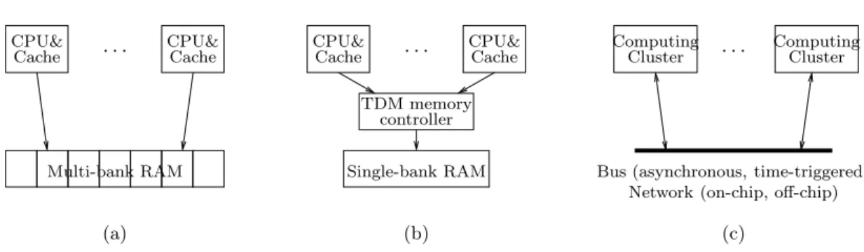
In the context of multi-processor systems, we believe that obtaining precise timing information is only possible if the hardware meets some basic assumptions ensuring that timing interference during concurrent access to shared resources can be tightly bounded. By shared resource we mean here all components of the hardware system that may introduce functional and temporal interferences between components. The shared resources we consider in our work are the memory subsystem, the buses and networks (including I/O), DMA controllers, and the synchronization subsystem.
. . .
TDM memory controller CPU&
Cache CPU&Cache CPU&Cache . . . CPU&Cache
Single-bank RAM
(b) (a)
. . .
Bus (asynchronous, time-triggered) Network (on-chip, off-chip) Computing
Cluster ComputingCluster
(c) Multi-bank RAM
Figure2 – Examples of execution platforms allowing simple contention avoidance : (a) Shared
multi-bank RAM (, (b) Shared single-bank RAM with TDMA arbiter, (c) Distributed, NUMA, or network-on-chip architecture (computing cluster = a or b).
Multi-processor systems with shared caches, although amenable to WCET estimation [11, 12], may yield pessimistic WCET estimates, because the state of these caches becomes difficult to approximate in the presence of concurrent requests. Our choice is to consider architectures where each processor has its own cache subsystem, independent from the ones of other processors. This general hypothesis covers caches with partitioning mechanisms, but in the experimental section of this paper we only consider cores with private L1 instruction and data caches, and no other caches.
For the scope of this paper, we make the following assumptions concerning the caches : – Each core has separate and private instruction and data caches. We consider such
architec-tures because separate caches are analyzable more precisely than unified caches by WCET estimation techniques.
– All caches have a Least Recently Used (LRU) replacement policy. LRU is assumed because it was shown to be the most predictable cache replacement policy [13].
Aside from shared caches, another significant source of WCET estimation imprecision is the presence of shared memory banks and shared communication busses. Our choice here is to consider architectures where the duration of all memory accesses and data transmissions can be precisely determined. As pictured in Fig. 2, the timing precision can be ensured :
– Fully by hardware mechanisms, for instance through the use of time division (TDM) me-mory controllers.
– Through a mix of software and hardware mechanisms. In these cases, software and/or hard-ware synchronization mechanisms (semaphores, locks) are used to guarantee the absence of contentions due to access to RAM banks or communication lines.
In this paper we consider architectures of the second type, as this case covers classical distributed bus-based architectures, shared memory architectures featuring multiple RAM banks, but also mixes of the two, such as the Network-on-Chip (NoC) based architectures proposed by various vendors [14, 15]. In particular, our NoC-based experimentation platform falls in this last case, and the aforementioned synchronization mechanisms are also used to control access to DMA controllers.
5
WCRT computation
Our approach to WCRT computation consists in extending a state-of-the-art WCET estima-tion method to compute WCRTs of parallel applicaestima-tions. The state-of-the-art WCET estimaestima-tion
8 Potop & Puaut core1_body N1 N3 N2 N4 N5 N6 N7 N8 N9 loop[12] loop[22]
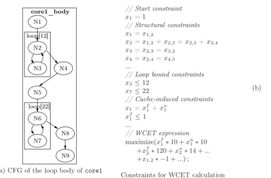
(a) CFG of the loop body of core1
// Start constraint x1 = 1 // Structural constraints x1 = x1,2 x2 = x1,2+ x2,3= x2,3+ x2,4 x3 = x2,3= x3,2 x4 = x2,4= x4,5 ...
// Loop bound constraints
x3 ≤12 x7 ≤22 // Cache-induced constraints x1 = xf1 + x n 1 xf1 ≤1 ... // WCET expression maximize(xf 1∗ 10 + x n 1∗ 10 +xf2∗ 120 + x n 2∗ 14 + ... +x1,2∗ −1 + ...) ; (b)
Constraints for WCET calculation
Figure 3 – State-of-the-art WCET calculation on the loop body of core1 in our illustrating
example.
technique we use as base for this extension is presented in Section 5.1 ; Section 5.2 then presents the extension itself.
5.1
Existing state-of-the-art WCET estimation technique
Static WCET estimation techniques are organized in three phases performing different ana-lyses [3] : Control-flow analysis, Hardware-level analysis and WCET calculation.
Control-flow analysis This phase extracts information about possible execution paths from
the program source or binary. The output of this phase is a data structure representing a superset of possible flows, represented by either a control flow graph (CFG) or a syntax tree. For the scope of this paper, we will represent the program control flow using a CFG, extracted from the program binary, and annotated with additional flow information such as maximum number of loop iterations. The CFG of the loop body of function core1 (from our sample application) is given in Fig. 3.a. In this figure, basic blocks of code are represented with circles, and control flow between basic blocks with arrows. Loops, annotated with their maximum number of iterations, are represented as rectangles.
Hardware-level analysis This step, also called low-level analysis, estimates the worst-case execution times of portions of sequential code, typically basic blocks. The difficulty during this task is to take into account micro-architectural components of (all) modern processors, such as caches, pipelines, branch predictors. In the presence of such components, the execution time of a statement is dependent on the context it is called in.
The hardware-level analysis is often made of several sub-analyses, one for each considered hardware component (instruction and data caches, pipelines, branch predictors, ...). The overall Inria
typical outcome of hardware-level analysis is a maximum execution time per basic block in two
different contexts to cope with cache effects : the first execution of the basic block, denoted tf
and its subsequent executions, denoted tn; (negative) execution times may also be associated to
edges to account for pipeline effects between basic blocks.
WCET calculation The purpose of this final phase is to determine an estimate for the WCET, based on the flow and timing information derived in the previous phases. The most wides-pread calculation method, that will be adopted in this paper, is called implicit-path enumeration (IPET). In IPET, program flow and basic-block execution time bounds are combined into sets of arithmetic constraints. Each entity (basic block or program flow edge) in the task is assigned two values :
– A time coefficient, denoted tentity, which expresses the upper bound of the contribution of
that entity to the total execution time every time it is executed.
– A count variable (xentity), corresponding to the number of times the entity is executed.
An upper bound of the WCET of the program is determined by maximizing the sum of products
of the execution counts and times (Pi∈entitiesxi∗ ti), where the execution count variables are
subject to constraints reflecting the structure of the task and possible flows. The result of an IPET calculation is an upper timing bound and a worst-case count for each execution count variable.
Fig. 3.b illustrates the constraints and formulas generated by an IPET-based bound calcu-lation method on the loop body of core1, assuming it is the program entry point. The start constraint states that the code is executed once. The structural constraints reflect the possible program flows, meaning that each basic block must be entered the same number of times as it is exited. The loop bounds constrain the number of executions of basic blocks inside loops. Cache induced constraints express that basic blocks have different execution times, one for their first execution, another for the next ones. In the WCET expression to be maximized, there are two
execution durations per basic block to model cache effects. For instance, in the formula, tf
2 = 120,
whereas tn
2 = 14.
5.2
WCRT computation
Starting from the WCET estimation method sketched above, we build our WCRT estimation technique for parallel applications. We were able to do so by only modifying the control flow analysis phase to make it :
– Add new edges between basic blocks to model synchronization/communications between tasks.
– Incorporate in the CFG the low-level information we need concerning inter-processor com-munications.
The 3 phases of the modified analyzer run as follows :
1. A new step dubbed Modelling of communications, is attached at the end of Control flow analysis. Once the classical control flow analysis runs (separately) on the functions/-tasks that are put in parallel, the new step adds new edges between the control flow graphs of these functions, the result being a single CFG. One new edge is added for each inter-task communication.
2. Hardware-level analysis. Application of the hardware-level analysis of the WCET esti-mation method runs unmodified on each function/task taken in isolation. During this first step, each task is analyzed as if it was not communicating with the other tasks executed on the other cores.
10 Potop & Puaut N13 N14 N15 N16 N17 N18 N19 N20 N2 N3 N4 N6 N7 N8 N5 N9 N1 loop[12] loop[22] core1_body st1 st3 st2 N21 N22 main loop[30] core2_body st4 st5 st6 N10 N11 N12
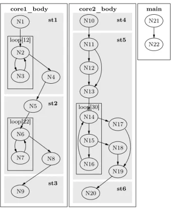
Figure4 – Original control flow graph for the toy example. Shaded areas represent task portions
between communications (subtasks)
3. WCRT computation. Even though the CFG corresponds to a parallel application, and has slightly different topological properties, the WCET calculation can be run unmodified. This is due to the fact that the analysis works by finding the critical path in a direc-ted acyclic graph (under certain constraints). That the graph represents purely sequential behaviors, or parallel ones (including the new edges that model communications) is not important.
The method is illustrated on our toy application of Fig. 1. Fig. 4 depicts the control flow graphs of the loop bodies of each of the two functions core1 and core2. In the figure, the shaded areas labeled st1-st6 correspond to sub-tasks, which are by definition parts of the two functions that are separated by inter-task communication primitives. For instance, node N4 of the core1_body CFG is the basic block containing the send call on channel1.
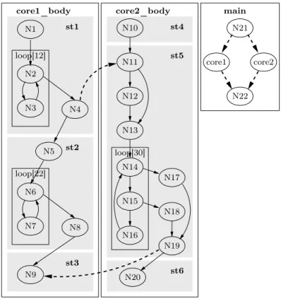
After the classical control flow analysis phase runs unmodified on the various sequential func-tions of the parallel program, the modelling of communicafunc-tions adds new edges in the application CFG to model communications. This is depicted by bold red arrows in Fig. 5. These new edges correspond to :
– Message passing between tasks (edges N 4 → N 11 and N 19 → N 9).
– Parallel launching of tasks on the different cores (edges to and from nodes N 21 and N 22 in the application entry point main).
Every new edge is associated a duration to model its execution time (message transmission time for communications).
N13 N14 N15 N16 N17 N18 N19 N20 N2 N3 N4 N6 N7 N8 N5 N9 N1 loop[12] loop[22] core1_body core1 core2 N21 N22 st1 st3 st2 loop[30] core2_body main st4 st5 st6 N10 N11 N12
Figure 5 – Control flow graph of our small example after adding communication arcs between
sequential tasks.
During the hardware analysis phase, our WCRT analysis method applies instruction and data cache analysis and pipeline analysis on the two CFGs core1_body and core2_body considered in isolation. This allows to benefit from the tightness of hardware-level analysis on each sub-task. For instance, in CFG core1_body, it allows to detect that array tqmf is still in the data cache after calling primitive send. This would not have been possible if a decoupled approach was used (WCET estimation of sub-tasks followed by WCRT estimation). If a decoupled method was used, conservative assumptions would have to be taken such that the analysis of sub-tasks is safe (assuming the worst-case hardware state, i.e. empty cache at WCET analysis start). Using an integrated approach, the first step of the analysis is able to capture hardware effects between sub-tasks (instruction caches, data caches, pipeline) naturally.
Finally, the WCET computation step is applied unmodified. Thanks to the introduction of the new edges, new constraints are automatically added in the WCET calculation equations (see new constraints below for the example), and communication delays are automatically taken into account.
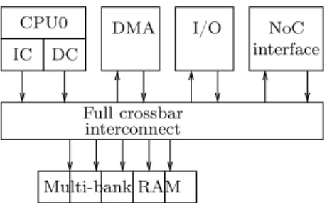
12 Potop & Puaut NoC CPU0 IC DC DMA Multi-bank RAM I/O Full crossbar interconnect interface
Figure6 – A processing element
// New or modified structural constraints
x4= x2,4 = x4,5+x4,10
x10= x9,10+x4,10 =x10,11+x10,12
// New WCET expression
maximize(xf 1∗ 10 + xn1∗ 10 + x f 2∗ 120 + xn2∗ 14 + ... +x4,10∗ 250 + x1,2∗ −1 + ...) ;
6
Experimental evaluation
6.1
Experimental setup
6.1.1 Multi-core architectureGiven that our claims mainly concern the precision of the timing analysis, we considered an evaluation platform allowing us to perform very precise (cycle-accurate) estimations and measurements of execution time, in both single-processor and multi-processor cases.
We achieved this by using the SocLib library [16] for virtual prototyping of multi-processor systems-on-chips (MPSoC). The hardware components we use are of cycle-accurate, bit accurate type, written in SystemC [17]. Synthesizable VHDL models exist for these components, allowing FPGA prototyping (although in this paper we only used the SystemC compiled simulators).
The precise architecture model we worked on using SocLib is a scaled-down version of that of [18]. While the original platform scales up to 4096 cores, we have only used single-, double-, and quad-core configurations for our tests. Our MPSoC is organized as a set of 1, 2, or 4 single-processor tiles, each one with the architecture of Fig. 6. As mentioned before, to facilitate cache analysis, each core has separate L1 instruction and data caches, and separate instruction and data memory. In the experimental setting of this paper all caches implement a Least Recently Used (LRU) cache replacement policy, and feature 32 sets, 4 ways, and 8 4-byte words per cache line. All CPU cores are of the same type, using the MIPS32 instruction set.
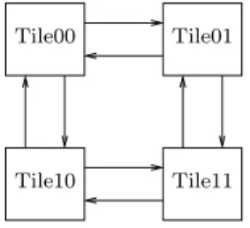
Processing elements are interconnected in a 2-D mesh using the DSPIN Network-on-Chip provided by SocLib. The quad-core configuration, for instance, is obtained by connecting 4 tiles in a 2x2 mesh, as pictured in Fig. 7 (the arrows represent communication lines of the Network-on-Chip).
The resulting hardware platform follows a distributed shared memory model, where all me-mory banks are assigned addresses in a global address space, and can be addressed by all CPU cores. Of course, memory access is of NUMA (Non-Uniform Memory Access) type, meaning that access time depends on the distance between the CPU and the addressed RAM bank.
Tile10
Tile00 Tile01
Tile11
Figure7 – The 4-core 2x2 mesh configuration
audio QMF (quadrature mirror filter) High-band encoder encoder Low-band Multiplexer audio compressed
Figure8 – Adaptive differential pulse-code modulation application
In building our tiles, we followed classical techniques for reducing access contentions. Thus, the local interconnect of each tile is a full crossbar, and each tile provides multiple RAM banks to allow non-interferent accesses to program text and data by the CPU cores (program and data) and DMA units. A set of hardware locks allows low-overhead synchronization between the CPU cores.
6.1.2 WCET estimation tool
The Heptane static WCET estimation tool [19] was used for the experiments. Heptane im-plements the its Implicit Path Enumeration Technique (IPET) WCET calculation technique. Regarding hardware-level analysis, Heptane supports instruction caches, data caches and pipe-line analysis. Heptane’s pipepipe-line analysis module was customized to analyze the pipepipe-line structure of each core.
Modifying Heptane to calculate WCRTs mainly consisted in adding a new analysis pass to Heptane, interposed between hardware-level analysis and WCET calculation, for a total volume of 200 lines of C++ code. Inter-task communications are detected by Heptane through annotations in the source code of the analyzed application, specifying at each communication point the recipient of the message and the communication latency.
6.1.3 Studied applications
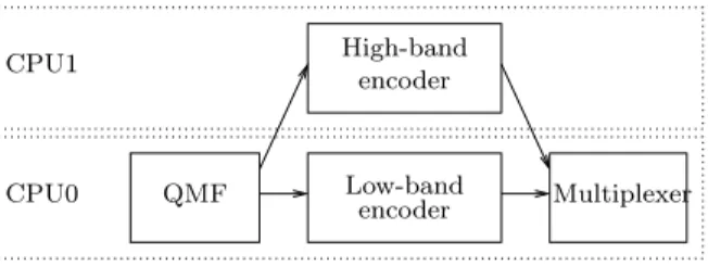
The proposed WCRT estimation method was experimented on two signal processing ap-plications. The first one is the complete parallel version of the adaptive differential pulse-code modulation (adpcm) from the Mälardalen WCET benchmark suite [10]. The global dataflow of the code executed at each iteration of the modulation applications is depicted in Fig. 8, where boxes represent subtasks and arrows communications/synchronizations between subtasks.
When parallelized for a 2-core architecture, the mapping of subtasks to cores is depicted in Fig. 9. Only the arrows crossing CPU boundaries are coded as communications ; the sequencing of QMF, low-band encoder and multiplexer is implemented simply by calling successively the
14 Potop & Puaut CPU1 encoder Low-band QMF Multiplexer encoder High-band CPU0
Figure 9 – Allocation and scheduling of adpcm on two processors
three codes in the main loop pf CPU0. When parallelized for a 4-core architecture, every subtask is assigned to a different core, and software pipelining is used to authorize more parallelism from the application. The communication latency of every inter-core communication was determined by an analysis of the hardware platform as a formula dependent on the volume of data to be transferred.
The second application is a simple load balancing example, where two processors are needed to improve the throughput of a simple image filter. In this bi-processor application, processor 0 successively receives image lines in a buffer. The buffer content must be stored elsewhere to allow a new line to arrive, and this new line will be sent to processor 1, cyclically.
Application code was compiled using a standard GNU Mips compilation toolchain.
For the scope of this performance evaluation, application code was parallelized manually. Automatic code parallelization software like [20] or offline real-time scheduling tools like [2] that generate efficient parallel code could have been used instead.
6.2
Experimental results
Demonstrating the tightness of our WCRT estimation method requires to : (i) demonstrate that the accuracy of the hardware model used in the base timing analysis tool with respect to the analyzed architecture ; (ii) compare WCRTs obtained using our integrated approach against those obtained using a decoupled estimation method ; (iii) compare WCRTs obtained with our tool with actual execution durations of the parallel code.
Accuracy of hardware model To show the accuracy of the hardware model used in the analysis, we have compared the number of cycles returned by the SocLib simulation software with the one returned by the Heptane timing analysis tool. Experiments were conducted on randomly generated sequential code, starting with known contents of the instruction of data caches. After a careful, extensive and always fastidious comparison of the analyzer and simulator cycle counts, both tools returned exactly the same number of cycles for all considered code. Comparison with baseline WCRT estimation method To evaluate the tightness of WCRT estimates, we have compared them with a baseline approach that estimates WCETs and WCRT separately. The baseline method :
– computes WCET of all sub-tasks (sequences of code between communications) separately ; to be safe, the worst-case hardware state is assumed by the static analyzer at the start of every subtask ;
– WCRTs are computed in an ad hoc manner according to the synchronization pattern of each task ; this turned out to be very easy for the considered applications, that have simple and regular communications, never more complex that the ones illustrated in Figure 1.
Table 1 – Worst-case response times of the considered applications using our approach (Inte-grated) and the baseline approach (Isolated). The improvement over the baseline approach is
defined as Isolated −Integrated
Integrated ∗ 100
Name Integrated Isolated Improvement
(cycles) (cycles) (%)
adpcm - 2 cores 73563 101431 36.5%
adpcm - 4 cores 44568 55919 25.5%
filter - 2 cores 110825 112543 1.55%
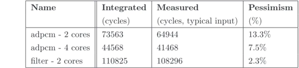
Table 2 – Worst-case response times of the considered applications using our approach
(In-tegrated) compared with observed response times (Measured). The pessimism is defined as
Integrated−Measured Measured ∗ 100
Name Integrated Measured Pessimism
(cycles) (cycles, typical input) (%)
adpcm - 2 cores 73563 64944 13.3%
adpcm - 4 cores 44568 41468 7.5%
filter - 2 cores 110825 108296 2.3%
The computed response time bounds are given in Table 1. The estimations produced by our integrated approach are always tighter than using the isolated method (21% in average on the three applications). The gain varies depending on the dependencies between subtasks of tasks running on the same core. When the amount of dependencies is high, like in application adpcm, that features intensive code and data reuse between subtasks, the gain is significant. When the amount of dependencies is smaller like in filter (no reuse of data, modest reuse of code between subtasks), the gain is much smaller.
Comparison with observed response times The pessimism of our WCRT evaluation me-thod is evaluated by comparing estimated WCRTs with observed ones, estimated using the SocLib simulation software. Regarding simulation results, due to time constraints, we made no attempt to identify the worst-case input data and execute the code with typical input data, not necessarily representative of the worst-case situation. The estimated pessimism is thus an upper bound of the method pessimism. Results are reported in Table 2.
The numbers show that even without executing the code using its worst-case input data, the results are encouraging : estimated and measured response times are close to each other (of 7.7% in average). Further experiments need to be conducted to identify the actual overestimation and not only an upper bound of the overestimation.
7
Conclusion
We have presented in this paper a method to compute the WCRTs of parallel applications running on multicore platforms. WCRTs computation is integrated into a WCET estimation me-thod such that hardware effects across portions of the application are dealt with naturally. We have demonstrated that our approach produces WCRTs that are tighter than using decoupled
16 Potop & Puaut
computations of WCETs and WCRTS (of 21% in average on three signal processing applications). Preliminary experiments show that the WCRT overapproximation is below 7.7% in average. The modification of a state-of-the-art WCET estimation tool turned out to be easy to achieve. We be-lieve that our method can be integrated easily in other WCET estimation tools using the implicit path enumeration techniques to the extent that the analysis framework is sufficiently modular (hardware-level analysis and WCET computation are clearly separated, and new analysis passes can be inserted in between).
In this paper, assumptions have been made regarding the software structure in order to demonstrate the validity of our approach on simple but yet realistic setting. In our future work, our first objective will be to relax as much as possible these assumptions to broaden the scope of application of the approach. Another area for future research will be to use obtained WCRTs to refine task placement and scheduling.
Références
[1] J. Kim, H. Oh, H. Ha, S. haeng Kang, J. Choi, and S. Ha, “An ilp-based worst-case perfor-mance analysis technique for distributed real-time embedded systems,” in IEEE Real-Time Systems Symposium, December 2012.
[2] T. Grandpierre and Y. Sorel, “From algorithm and architecture specification to automa-tic generation of distributed real-time executives,” in Proceedings MEMOCODE, Mont St Michel, France, 2003.
[3] R. Wilhelm, J. Engblom, A. Ermedahl, N. Holsti, S. Thesing, D. Whalley, G. Bernat, C. Fer-dinand, R. Heckmann, T. Mitra, F. Mueller, I. Puaut, P. Puschner, J. Staschulat, and P. Stenström, “The worst-case execution-time problem overview of methods and survey of tools,” ACM Transactions on Embedded Computing Systems, vol. 7, no. 3, pp. 36 :1–36 :53, May 2008.
[4] K. Tindell and J. Clark, “Holistic schedulability analysis for distributed hard real-time sys-tems,” Microprocessing and Microprogramming, vol. 40, no. 2-3, pp. 117–134, Apr. 1994. [5] J. J. G. García, J. C. P. Gutiérrez, and M. G. Harbour, “Schedulability analysis of distributed
hard real-time systems with multiple-event synchronization,” in Proceedings of the 12th Euromicro conference on Real-time systems, 2000, pp. 15–24.
[6] M. Bertogna and M. Cirinei, “Response-time analysis for globally scheduled symmetric mul-tiprocessor platforms,” in Real-Time Systems Symposium, 2007. RTSS 2007. 28th IEEE International, Dec. 2007, pp. 149–160.
[7] M. Kuo, R. Sinha, and P. Roop, “Efficient wcrt analysis of synchronous programs using reachability,” in Proceedings DAC’11, San Diego, CA, USA, 2011.
[8] C. Rochange, A. Bonenfant, P. Sainrat, M. Gerdes, J. Wolf, T. Ungerer, Z. Petrov, and F. Mikulu, “Wcet analysis of a parallel 3d multigrid solver executed on the merasa multi-core.” in Proceedings of the 10th International Workshop on Worst-Case Execution Time Analysis, in conjunction with ECRTS 2010, 2010.
[9] F. Nemer, H. Cassé, P. Sainrat, and J. P. Bahsoun, “Inter-task wcet computation for a-way instruction caches,” in IEEE Third International Symposium on Industrial Embedded Systems - SIES 2008, Montpellier / La Grande Motte, France, 11-13 June 2008, 2008, pp. 169–176.
[10] J. Gustafsson, A. Betts, A. Ermedahl, and B. Lisper, “The Mälardalen WCET benchmarks – past, present and future,” in Proceedings of the 10th International Workshop on Worst-Case Execution Time Analysis, in conjunction with ECRTS 2010, Jul. 2010, pp. 137–147.
[11] Y. Li, V. Suhendra, Y. Liang, T. Mitra, and A. Roychoudhury, “Timing analysis of concur-rent programs running on shared cache multi-cores,” in Proceedings of the 30th IEEE Real-Time Systems Symposium, RTSS 2009, Washington, DC, USA, 1-4 December 2009, 2009, pp. 57–67.
[12] D. Hardy, T. Piquet, and I. Puaut, “Using bypass to tighten wcet estimates for multi-core processors with shared instruction caches,” in Proceedings of the 30th IEEE Real-Time Systems Symposium, RTSS 2009, Washington, DC, USA, 1-4 December 2009, 2009, pp. 68–77.
[13] J. Reineke, D. Grund, C. Berg, and R. Wilhelm, “Timing predictability of cache replacement policies,” Real-Time Systems Journal, vol. 37, no. 2, pp. 99–122, Nov. 2007.
[14] M. Harrand and Y. Durand, “Network on chip with quality of service,” United States patent application publication US 2011/026400A1, Feb. 2011.
[15] L. Benini, “Programming heterogeneous many-core platforms in nanometer technology : the p2012 experience,” Presentation in the ARTIST Summer School, Autrans, France, Sep 2010, online at : http ://www.artist-embedded.org/artist/Videos.html.
[16] LIP6, “SoClib : an open platform for virtual prototyping of multi-processors system on chip,” 2011, online at : http ://www.soclib.fr.
[17] T. Grotker, System Design with SystemC. Kluwer Academic Publishers, 2002.
[18] M. Djemal, R. de Simone, F. Pêcheux, F. Wajsbürt, D. Potop-Butucaru, and Z. Zhang, “Programmable routers for efficient mapping of applications onto noc-based mpsocs,” in Proceedings DASIP, Karlsruhe, Germany, 2012.
[19] A. Colin and I. Puaut, “A modular and retargetable framework for tree-based wcet analysis,” in Real-Time Systems, 13th Euromicro Conference on, 2001., Jul. 2001, pp. 37 –44. [20] U. Bondhugula, A. Hartono, J. Ramanujam, and P. Sadayappan, “A practical automatic
polyhedral parallelizer and locality optimizer,” in Proceedings of the 2008 ACM SIGPLAN conference on Programming language design and implementation, ser. PLDI ’08, 2008, pp. 101–113.
RESEARCH CENTRE PARIS – ROCQUENCOURT
Domaine de Voluceau, - Rocquencourt B.P. 105 - 78153 Le Chesnay Cedex
Publisher Inria
Domaine de Voluceau - Rocquencourt BP 105 - 78153 Le Chesnay Cedex inria.fr
![Figure 1 – Toy illustrating example : Code snippets of a parallel version of the adpcm benchmark from the Mälardalen WCET benchmark suite [10]](https://thumb-eu.123doks.com/thumbv2/123doknet/12962685.376948/8.892.105.740.417.845/figure-illustrating-example-snippets-parallel-benchmark-mälardalen-benchmark.webp)