HAL Id: hal-01393993
https://hal.archives-ouvertes.fr/hal-01393993
Submitted on 8 Nov 2016
HAL is a multi-disciplinary open access
archive for the deposit and dissemination of
sci-entific research documents, whether they are
pub-lished or not. The documents may come from
teaching and research institutions in France or
abroad, or from public or private research centers.
L’archive ouverte pluridisciplinaire HAL, est
destinée au dépôt et à la diffusion de documents
scientifiques de niveau recherche, publiés ou non,
émanant des établissements d’enseignement et de
recherche français ou étrangers, des laboratoires
publics ou privés.
Radiation efficiency measurement of a balanced
miniature IFA-inspired circular antenna using a
differential Wheeler cap setup
Francois Sarrazin, Sylvain Pflaum, Christophe Delaveaud
To cite this version:
Francois Sarrazin, Sylvain Pflaum, Christophe Delaveaud. Radiation efficiency measurement of a
balanced miniature IFA-inspired circular antenna using a differential Wheeler cap setup. International
Workshop on Antenna Technology (IWAT 2016), Feb 2016, Cocoa Beach, FL, United States. pp.64,
�10.1109/IWAT.2016.7434802�. �hal-01393993�
Radiation Efficiency Measurement of a Balanced
Miniature IFA-Inspired Circular Antenna using a
Differential Wheeler Cap Setup
F. Sarrazin, S. Pflaum and C. Delaveaud
CEA-Léti, Minatec Campus Grenoble, France francois.sarrazin@cea.fr
Abstract—This paper presents the radiation efficiency
measurement of a novel balanced miniature IFA-inspired circularly folded antenna whose maximum dimension is / at 433 MHz. The measurement is performed using a Wheeler cap (WCap) and a differential measurement setup using two feeding coaxial cables. Original narrowband WCap method is compared to the Ultra Wide Band (UWB) WCap approach. The accuracy of the measurement is discussed and additional simulations are performed to understand the overestimated results measured by the WCap method.
Keywords—balanced antenna, electrically small antenna, IFA, radiation efficiency, Wheeler cap
I. INTRODUCTION
Electrically Small Antennas (ESAs) have been first studied by the early work of Wheeler [1] and are defined according to
< 0.5 where is the wavenumber and is the minimum
sphere circumscribing the antenna, now known as the radiansphere [2]. A year later, Chu [3] derived the minimum Q-factor that an ESA can reach as a function of . This equation highlighted the tradeoff between size, radiation efficiency and bandwidth, that has to be made when dealing with ESAs. The radiation efficiency is a crucial parameter in small antenna design since it characterizes the ability of an antenna to radiate the power it accepts (in emitting mode) or to transfer the power it receives (in receiving mode). Antenna radiation efficiency can be measured using different techniques depending on the measurement setup. It can be calculated from near-field or far-field radiation properties [4]. Considering ESAs, radiation properties measurement can become very tricky using classical invasive method. Indeed, cables are needed to feed the antenna and appear to radiate as least as much as the antenna itself [5].
In order to make easier and quicker the efficiency measurement of ESAs, Wheeler introduced a new method, now known as the Wheeler Cap (WCap) [2] based only on the measurement of the reflection coefficient of the antenna in free space (FS) and placed inside a spherical cavity. It is then possible to compute the radiation efficiency from these two results. McKenzie [6] enhanced this method to be applicable to a larger number of antennas. The WCap method being narrowband, Schantz [7] developed a new WCap method to be used with UWB antennas, called the UWB WCap. A few years
later, Huynh [8] slightly modified Schantz equation to enhance its accuracy. Researches are still ongoing to improve WCap accuracy for UWB antennas, for example by using source-stirring [9]-[10]. WCap measurements have been frequently performed with antennas on a limited ground place. In the case of ESA efficiency measurement using the WCap method, the possible alteration of the measurement cable is rarely discussed. In this paper, we focus on measurement of balanced small antennas. Thus, a differential measurement setup [11] is used both in FS and inside the cavity, in order to avoid errors due to the leakage current flowing back along the feeding cable. This method is based on two coaxial cables to feed the balanced antenna.
In section II, a balanced Miniature IFA-Inspired Circularly-folded Antenna is introduced. Its impedance measurement, based on a differential setup, is compared to the simulation to validate the approach. Then, section III presents the radiation efficiency measurement with WCap, still using the differential setup. Different formulas to compute the radiation efficiency (Wheeler, Schantz and Huynh) are compared and results are discussed.
II. MINIATURE IFA-INSPIRED CIRCULARLY-FOLDED ANTENNA
We consider the antenna presented in Fig. 1 designed to operate at 433 MHz (λ=70 cm). It is a differential Miniature IFA-Inspired Circularly-folded Antenna (MIICA), terminated by a two-wire line acting as a load capacitor (antenna miniaturization). The diameter is 50 mm ( /14 at the working frequency or = 0.2267 where is the wavenumber and
Fig. 1. Realized prototype of the considered miniature IFA inspired circularly folded antenna fed by two coaxial cables terminated by SMA connectors. Its diameter is 50 mm and the strip is 1 mm wide.
the radius) and the capacitor is 20.4 mm long. The shorting strip used for impedance matching is 8 mm wide and located 2 mm away from the feed. The copper strips width is 1 mm and the substrate is a 0.8 mm thickness Rogers RO3003 ( = 3). This
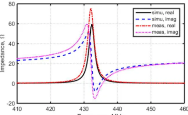
antenna is simulated with ANSYS [12] using a lumped port located between the two antenna arms. The simulated input impedance and reflection coefficient are presented as a function of the frequency in Fig. 2 and Fig. 3, respectively. We can notice that the input impedance presents an antiresonance at 432.7 MHz and that it is correctly matched to 50 Ω with a 1.5 MHz bandwidth ( < 10 ), i.e. a 0.35 % relative bandwidth. The simulated radiation efficiency is equal to 38 % taking into account the ohmic and dielectric losses due to the copper strips and the substrate.
Feeding balanced antennas with a single unbalanced coaxial cable can lead to altered results mainly due to leakage current flowing back on the shield (radiation efficiency improvement). To avoid this, one solution consists of using a balun that forces opposite currents in each part of the antenna. The quality of the used balun can drive the measured performances of the antenna. Here, we propose to use a differential approach based on two coaxial cables to feed the antenna. Each core is connected to one antenna arm and the shields are soldered together. On the other side, the cables are terminated by SMA connectors to be connected to the VNA. First, the VNA is calibrated in a classical way. Then, we need to perform a deembedding of the two soldered cables. Thus, the S-parameters of these cables when terminated by a short-circuit and a 50 Ω load are measured. The S-parameters of one cable are deduced from this measurement by assuming the two cables are identical (same length). Then, the S-parameters of the whole system (cables and antenna) are also measured. From these measurements and using abcd matrices, the S-parameters of the antenna alone is obtained as
1 1 − − = cable tot cable ant c d b a d c b a d c b a d c b a . (1)
Finally, the differential antenna input impedance is computed from the S-parameters of the antenna alone as
21 12 22 11 22 11 21 12 0 ) 1 )( 1 ( ) 1 )( 1 ( 2 S S S S S S S S Z Zdiff − − − − − − = (2)
where is the characteristic impedance (50 Ω) of the feeding coaxial cables.
The measured input impedance and reflection coefficient are presented in Fig. 2 and Fig. 3, respectively, as a function of the frequency. The measures are in very good agreement with the simulated results using a lumped port.
III. MEASUREMENT SETUP USING WHEELER CAP AND
DIFFERENTIAL FEEDING
The radiation efficiency is a very important parameter that describes how well an antenna radiates the power accepted at its feed. The radiation efficiency is usually measured by integrating the gain pattern of an antenna over the whole sphere. Depending on the antenna measurement setup, this technique can be
time-consuming. In 1959, Wheeler introduced a new kind of efficiency measurement known as the Wheeler cap (WCap) method. The WCap is a sphere of radius = ⁄2 that is physically located at the transition between the antenna near-field (inside the cavity) and the far-near-field (outside of the cavity) [2]. If the antenna is located at the center of the sphere, its radiation impedance is short-circuited and thus cancelled by the WCap ( = 0). In this way, the antenna input impedance
when the antenna is placed inside the WCap is equal to the loss impedance ( _ = = ) that is computed as WC WC loss S S Z Z 11 11 0 1 1 − + = . (3)
where is the antenna reflection coefficient measured with the antenna placed inside the WCap. Then, since the MIICA can be seen as a parallel RLC circuit at its resonance, its radiation efficiency can be computed as
) Re( ) Re( ) Re( loss loss ant rad Y Y Y − = η . (4)
where and are the antenna admittance (measured in Free-Space (FS)) and the loss admittance (deduced from the WCap measurement), respectively and stands for the real part. In 1997, McKinzie [6] extends this method to be applied to any antenna and not only those equivalent to parallel or serial RLC circuit. The measured reflection coefficients (FS and
Fig. 3. Simulated and measured reflection coefficient of the MIICA.
Fig. 2. Simulated and measured input impedance of the MIICA.
WCap) are both rotated before computing the radiation efficiency in a same way than in the original Wheeler method. The main drawback of these approaches is the very narrow bandwidth. Indeed, the WCap method is valid only at the antenna resonant frequency.
In 2002, Schantz [7] introduced a new WCap-based method that is valid for UWB antenna: the “UWB WCap” method. The antenna under measurement is still placed inside a spherical cavity whose radius is not anymore exactly equal to /2 but instead /2 . For such dimensions, the antenna radiates
freely inside the cavity. The reflections that occur on the cavity come back to the antenna that radiates again, accordingly to its radiation efficiency and input impedance, and so on. In the end, the radiation efficiency can be expressed as
) )( 1 ( 11 2 2 11 2 11FS WC FS rad = − S S − S η . (5)
A few years later, Huynh [8] realized that Schantz equation does not take into account the antenna reflection coefficient in the very first step of the process and modified (5) into
) 2 1 11 2 11 2 11 2 2 11 2 11 FS WC FS FS WC rad S S S S S + − − = η . (6)
In this paper, we use the WCap method associated with differential impedance measurement. The measurement setup is presented in Fig. 4. The two coaxial cables that come out of the VNA are connected to two small cables that pass through the WCap from the bottom and whose shields are soldered to the WCap. Inside the WCap, these cables are terminated by SMA connectors to be connected to the antenna under measurement. The WCap has been designed to operate at 433 MHz, i.e. its radius is equal to /2 at this frequency so both conventional and UWB WCap methods can be applied. The antenna is placed at the center of the sphere. Since there are additional cables compared to the free-space measurement (those who make the link between outside and inside the WCap), another calibration is made for the deembedding.
IV. RESULTS
The radiation efficiency measurement using the setup presented in the previous section is shown in Fig. 5 as a function of the frequency. Three different equations are compared: the original Wheeler one, Schantz and Huynh. First of all, it has to be noticed that although the radiation efficiency is plotted from 428 MHz to 434 MHz, Wheeler’s result is valid only at the resonant frequency (432.7 MHz) and Schantz and Huynh are valid starting from this resonant frequency. However, it is interesting to see that the three approaches seem to converge to the same value at the resonant frequency, i.e. about 50 % at 432.7 MHz. The measured radiation efficiency is consequently 12 % higher than the simulated one (50 % compared to 38 %). To evaluate possible inaccuracies due to the experimental setup, the MIICA is simulated with two coaxial cables feeding the antenna arms as presented in Fig. 6. It is excited by two waveports in opposite phase. The antenna radiation efficiency obtained for cables’ length from 0 mm to 500 mm are presented in Fig. 7. We can see that the efficiency almost doesn’t vary with respect to the length of the feeding cables. It actually increases
Fig. 4. Measurement setup of the MIICA placed inside the Wheeler cap and connected to the VNA.
Fig. 5. Measured radiation efficiency of the MIICA using the WCap with three different approaches as a function of the frequency.
Fig. 7. Simulated radiation efficiency of the MIICA at 432.7 MHz as a function of the cables’ length.
Fig. 6. Design of the simulated MIICA with the two coaxial cables of variable length .
of 1 % starting from = 50 mm but does not increase
anymore for longer cables, proving that correctly fed differential antenna are not sensitive to balanced twin cable system. Thus, it is not possible to explain the difference between the simulated and measured radiation efficiency by the presence of the cable system. However, the latter study shows clearly the interest of a differential measurement setup. Indeed, since almost no current flows back on the cables’ shield, the cables don’t radiate and the measurements are only due to the antenna performances.
In order to better understand the behavior of the measured efficiency, we simulate the WCap measurement process. Thus, the MIICA is simulated inside a spherical cavity whose radius varies from 0.1 λ to 0.2 λ. Notice that ⁄2 0.16 . The
reflection coefficients obtained for some specific WCap radius are compared to the reflection coefficient simulated in FS in Fig. 8. We observe that the reflection coefficient is modified when the antenna is placed inside the cavity. Its minimum is shifted to a higher frequency and the smaller the spherical cavity, the larger the shift. From these simulations and the one in FS, the radiation efficiency is computed using the three different equations. Results are presented in Fig. 9 as a function of the WCap radius. First of all, we can see that the three computed efficiencies linearly decrease as a function of the WCap radius. Recall that the Wheeler equation is valid only for a ⁄2 0.16 -radius sphere. The efficiency obtained from WCap
simulation and original Wheeler approach is thus equal to 63 % which is 13 % higher than the measured value and 25 % higher than the directly simulated value. Regarding the UWB results (Schantz and Huynh), the two curves are very close. For a radius
2
⁄ 0.16 , the simulated radiation efficiency is 50 % that is
the same that the measured value. However, the UWB methods should be valid for any sphere radius higher than 0.16 but we can see the simulated efficiency decreases for higher values while it should be constant.
As a conclusion, the radiation efficiency obtained from WCap measurement is higher that the simulated value but the three different approaches (Wheeler, Schantz and Huynh) lead to the same results. Moreover, this value has been confirmed by WCap simulations at least for the UWB methods. Thus, the differential measurement setup inside the WCap can be validated although WCap measurements seem to not be accurate enough to measure the radiation efficiency of this miniature antenna.
V. CONCLUSION
A novel Miniature IFA-Inspired Circularly-folded Antenna (MIICA) has been introduced. It presents small size ( /14 at 433 MHz) and good efficiency (38 %). A radiation efficiency measurement based on WCap and differential feeding system is performed and validated. However, the WCap method itself seems to be not accurate enough to characterize the radiation efficiency of this antenna. Comparison with radiation efficiency measured in far-field anechoic chamber will be presented during the conference.
ACKNOWLEDGMENT
This work is financially supported by the French Research Agency under the project SENSAS (ANR-13-INFR-0014).
REFERENCES
[1] H. A. Wheeler, “Fundamental limitations of small antennas,” Proc. IRE, vol. 35, pp. 1479-1484, 1947.
[2] H. A. Wheeler, “The radiansphere around a small antenna,” Proc. IRE, vol. 47, pp. 1325-1331, 1959.
[3] L. J. Chu, “Physical limitation on omnidirectional antennas,” Journal of Applied Physics, vol. 19, pp. 1163-1175, 1948.
[4] D. M. Pozar and B. Kaufman, "Comparison of three methods for the measurement of printed antenna efficiency," IEEE Trans. on Ant. and Prop., vol. 36, no. 1, pp. 136-139, Jan 1988.
[5] L. Le Coq, C. Marchais, P. Besnier, A. Sharaiha and G. Le Ray, "Small and ultra wide band antennas : A new challenge for characterisation," in European Conf. on Ant. and Prop., pp.1-4, 6-10 Nov. 2006.
[6] W. E. McKinzie, "A modified Wheeler cap method for measuring antenna efficiency," Antennas and Propagation Society International Symposium, pp. 542-545, 13-18 July 1997.
[7] H. G. Schantz, "Radiation efficiency of UWB antennas," IEEE Conference on Ultra Wideband Systems and Technologies, Digest of Papers, pp. 351-355, 21-23 May 2002.
[8] M. Huynh, “Wideband compact antennas for wireless communication applications,” Ph.D. Dissertation, Virginia Polytechnic Instit. and State Univ., Blacksburg, VA, 2004.
[9] N. Pires, C. Mendes, M. Koohestani, A. K. Skrivervik and A. A. Moreira, "Novel Approach to the Measurement of Ultrawideband Antenna Efficiency," in IEEE Antennas and Wireless Propagation Letters, vol. 12, no., pp. 1512-1515, 2013.
[10] Y. Huang, L. Yang, S. Boyes and L. Tian-Hong, "Source-stirred chamber/cap method for antenna radiation efficiency measurements," in Eur. Conf. on Ant. and Prop. (EUCAP), pp.164-168, 11-15 Apr. 2011. [11] Meys, R.; Janssens, F., “Measuring the impedance of balanced antennas
by an S-parameter method," IEEE Antennas and Propagation Magazine, vol. 40, no. 6, pp. 62-65, Dec. 1998.
[12] ANSYS® Electromagnetics Suite, Release 16.0. Fig. 8. Simulated reflection coefficient as a function of the frequency of the
MIICA in free-space (FS) and inside a Wheeler Cap (WC) for several radius expressed in λ.
Fig. 9. Simulated radiation efficiency of the MIICA obtained using a WCap approach as a function of the WCap radius expressed in λ.