Development of Arduino Based Quadcopter
Anurag Singh Rajpoot1, Namrata Gadani1, Sagar Kalathia1
Students, Department of Electronics & Communication, L.D. College of Engineering, Ahmedabad, India 1
Abstract: The internal aspects of the Quadcopter based on Arduino UNO development board is enlightened through
this paper. It also explains about the maximum weight lifting capacity of the Quadcopter and the other various parameters relevant to transmitter-receiver, gyroscope, electronic speed controllers (ESCs), PID control etc. The paper emphasize on making Quadcopter cost-effective and reliable along with making it highly stabilized in windy and dusty environment. Also we have tried to make it multi-tasking through module based approach for having a single Quadcopter to be used for multiple tasks.
Keywords: Quadcopter, UAV, Arduino, PID, Autonomous Flight. I. INTRODUCTION
The arena of application for quadcopter is escalating day by day. From defence to agricultural farms, quadcopter finds its application everywhere. Today quadcopter is used for aerial surveillance, pesticide sprinkling, delivery purpose, ground mapping etc.
Pesticide sprinkler using quad-copter is basically a combination of a sprinkler on a Quad copter frame, where as in surveillance quadcopter it is endowed with a camera whose output is monitored on remote desktop. For delivery purpose, quadcopter are made to carry light weight stuffs from one location to other by using GPS navigation. Quadcopter plays vital role for ground mapping for small congested area with high accuracy and resolution.
Quadcopter nowadays are replacing normal day to day services with in-fusion of speedy deliveries and faster results. There is widespread research and development possible in this spectrum. Making a quadcopter which could function in all the arenas as stated above can open a new dimension in the field of quadcopter building
II. SYSTEMDIAGRAM&ITSDESCRIPTION
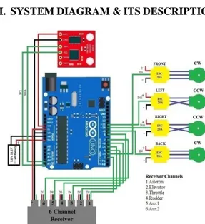
Fig. 1. System diagram of Quad-Copter
Software Arduino 1.6.5
Development Board Arduino UNO Processor Atmel ATMega328 P Power Supply 3 Cell LiPo Battery-11.1 V
Gyro L3G4200D
BLDC Motor 1400kV 10T
ESC 30A
Propellers 10x4.5 Propellers Black CW CCW
ZigBee 2mW
Quad-copter Frame F450
Table 1: Description of main system diagram Fig. 1 shows the system diagram comprising of Arduino UNO development board consisting of Atmel Atmega328P IC as the main brain of the quadcopter. The other interfaces to it are gyroscope, four BLDC (Brushless DC) motors connected through corresponding Electronic speed controller (ESC), LiPo (Lithium Polymer) battery which is of 11.1V when fully charged and six-channel receiver. The Receiver Channels are:
1. Aileron 2. Elevator 3. Throttle 4. Rudder 5. Aux 1 6. Aux 2
Out of four BLDC motors two motors facing each other are connected in such a manner that they will rotate CW (Clockwise) while the rest of two facing each other will rotate CCW (Counter Clockwise). Thus, this the basic arrangements on the Quadcopter frame.
IV. COMPONENTSANDHARDWARES
A. Atmel Atmega 328P
The device is manufactured using Atmel’s high density non-volatile memory technology. The On-chip ISP Flash allows the program memory to be reprogrammed In-System through an SPI serial interface, by a conventional nonvolatile memory programmer, or by an On-chip Boot program running on the AVR core. The Boot program can use any interface to download the application program in the Application Flash memory. Software in the Boot Flash section will continue to run while the Application Flash section is updated, providing true Read-While-Write operation. ATmega328/P is a powerful microcontroller that provides a highly flexible and cost effective solution to many embedded control applications. The ATmega328/P AVR is supported with a full suite of program and system development tools including: C Compilers, Macro Assemblers, Program Debugger/Simulators, In-Circuit Emulators and Evaluation kits.[4]
B. Arduino UNO
Arduino is an open-source prototyping platform based on easy-to-use hardware and software. Arduino boards are able to read inputs - light on a sensor, a finger on a button, or a Twitter message - and turn it into an output - activating a motor, turning on an LED, publishing
something online. Arduino IDE (Integrated Development Environment) is use to upload programs to the arduino Boards and these microcontroller boards can be used to perform intended tasks.[6]
C. BLDC motor
A typical brushless motor has permanent magnets which rotate around a fixed armature, eliminating problems associated with connecting current to the moving armature. Brushless motors offer several advantages over brushed DC motors, including high torque to weight ratio, more torque per watt(increased efficiency), increased reliability, reduced noise, longer lifetime (no brush and commutator erosion), elimination of ionizing sparks from the commutator, and overall reduction of electromagnetic interference(EMI). With no windings on the rotor, they are not subjected to centrifugal forces, and because the windings are supported by the housing, they can be cooled by conduction, requiring no airflow inside the motor for cooling. BLDC motors are rated in KV where it rotates 1000 rpm per 1 Volt supplied to it if its rating is 1 KV. [7]
D. Electronic Speed Controllers
Four 30A ESCs (electronic speed controllers) are used in proposed Quadcopter, it’s used to control the voltage applied to the BLDC motor as per the PWM signals it receives from Microcontroller digital pins. As we are using 30A ESC so the maximum current it can handle is 23A
The function of electronic speed controller for brushless motor:
1. Reset to factory default
2. Battery types set (LiPo or NiMh/NiCd) 3. Brake set (yes/no)
4. Threshold set of protection for low voltage (set a protective value for low voltage)
5. Motor entrance angle set (improve the service efficiency of ESC and the stability in the starting)
6. Accelerated start-up set (used in precise gear box and application of helicopter)
7. Helicopter mode (used in application of helicopter) 8. Steering motor (clockwise/anticlockwise)
9. Operating frequency set
10. Protection mode under low voltage (reduces power or halts immediately)
E. LiPo battery
The main use of LiPo battery over here is that it provides large current required for operating the BLDC motors. We are using 3000mAh LiPo battery of 30C-40C discharging rate of 11.1V (3S), this indicates that when 3000mA load is placed across it then it will take 1 hour to discharger completely.
So maximum source power it can provide is 90A(3000mAh * 30C), it’s also to be remembered that the
LiPo batteries can’t be used below 80% of the maximum capacity.
F. LiPo battery charger
11.1 Volt LiPo battery can be 100% charged when it’s charged up to 12.6 Volt. The charger as shown in the above picture is used as a 3 cell charger specially for LiPo battery.
G. Quad-copter Frame
The F-450 quad copter frame is used as it’s suitable for the propellers and the payloads which have to be lifted.
H. Propellers
10x4.5 Propellers Black CW CCW 4 pieces. We have used these as per the requirements.
I. Solar Panel:
Solar plate can be used as an alternate source while using this product in daytime. The solar plates can make this thing more efficient through solar energy while sprinkling during sunny days. Solar modules use light energy (photons) from the sun to generate electricity through the photovoltaic effect.
The majority of modules use wafer-based crystalline silicon cells or thin-film cells based on cadmium telluride or silicon. The structural (load carrying) member of a module can either be the top layer or the back layer. Cells must also be protected from mechanical damage and moisture. Most solar modules are rigid, but semi-flexible ones are available, based on thin-film cells.
J. 6 Channel Transmitter-Receiver
The 6 channel tx/rx are used to control the Quadcopter by using only first four channel of it. The remaining two channels can be used to control the modules attached to it.
K. Gyroscope
The L3G4200DH gyroscope is a low-power three-axis angular rate sensor. It includes a sensing element and an IC interface able to provide the measured angular rate to the external world through digital interface (I2C/SPI).[5]
V. QUADCOPTERMOVEMENTS
The thrust and torque are the very basic two things used for movement of quadcopter. The movement are decided on the input values(x, y, z, θ, ɸ, ψ) provided to it. The movements are:
A. Yaw Rotation
Each of rotors on the device produces both thrust and torque. Initially there are front-left and rear-right motors both rotate counter clockwise and other two rotate clockwise, the net aerodynamic torque will be zero [3]. Yaw decides the direction of the quadcopter.[2]
Fig. 2. Yaw Rotation
B. Pitch Rotation
Motion of the Quadcopter about the lateral axis is termed as pitch. It decides the movement of quadcopter either forward or backward. [2]
Fig. 3. Pitch Rotation
C. Roll Rotation
Motion of the Quadcopter about the longitudinal axis is called as roll. It makes Quadcopter to fly either right or left.[2]
Fig. 4. Roll Rotation
VI. DESIGNANDMETHODOLOGY
Fig. 5. Final Arduino based Quadcopter design
A. Receiver testing & End-points of Transmitter stick
setting
The pulse ranging from 1000µs to 2000µs can be given to the quadcopter since these are the limits for achieving the better performance of BLDC motors. The receiver’s first four channels are fed to the Arduino.
While the lowest stick position of all the four channels in the transmitter is set to 1000µs and the uppermost stick position is set to 2000µs. Thus, all the four channels of receiver can receive the pulses in between 1000µs to 2000µs based on user’s input and control.
This setting can be achieved in two ways: 1. Using CRO
TEST & RESULTS
Fig. 6 Setting of the end-points for transmitter’s sticks using CRO.
Fig. 6 shows the arrangements and the pulse width for the lowest position which is of 1000µs width (2-divisions * 500µs/division) through green line. If the stick position is in centre for the other channel then it will show 1500µs since each stick controls two channels one in up-down direction while other in left-right direction.
Fig. 7. Arduino 1.6.5 serial monitor output for all sticks in centre position
Fig. 7 shows when all the four channels are in centre position their output is 1500µs. The end-points of transmitter is set using the sub-trim in case is not matching with our requirements. Sub-trim can be set manually or through software too.
B. Gyroscope data reading by Arduino
The 16-bit data of gyro for any rate of change of angular movement is collected by Arduino through I2C
communication in our case.
Fig. 8. I2C data transfer between Arduino and the Gyro.
TEST & RESULTS
Fig. 9. Arrangement for testing of Gyroscope using CRO Fig. 9 depicts the gyroscope sensing the angular rate changes. A program is loaded in Arduino which makes two division wide pulse on the CRO when no angular rotation is sensed. The additional length of the pulse is linearly coupled to the angular rate of the gyro. The length of the pulse changes when the gyro is rotated. It was successfully tested
Fig. 10. Arduino 1.6.5 serial monitor output for Right Wing UP & DOWN
As shown in Fig. 10 the output of the serial monitor shows that when the right-wing of the Quadcopter was made UP the gyro sensed it, similarly for DOWN activity it again sensed the data in reverse direction. So, the same testing was done for Nose UP & DOWN (pitch) as well as Nose LEFT-RIGHT (yaw). Thus in this manner the gyro interfaced with arduino on Quadcopter was tested.
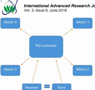
C. PID Control
Proportional-Integral-Derivative controller is a type of feedback based control system that is most widely used in automation processed. The algorithm of a PID controller revolves around the three separate constant parameters and is sometimes referred as three term control.
Independently P denotes the present error, I denotes accumulation of past errors and D is the prediction of future errors. The weighted sum that is generated from these terms is then used to adjust the deviation in the process. Thus PID controller is an error based system which works by minimizing the error between measured process and a desired set point.
Fig. 11. The basic principle of PID Controller The three terms of the PID contribute to the manipulated variable (MV) i.e. the process to be controlled. The individual components are than added to find output of the PID. If u(t) is the controller output than
u(t) = MV(t) = KP
e
(t
)
+ KIe
d
t
0(
)
+ KDdt
e
(t
)
d
KP= Proportional gain, a tuning parameter
e = Error
KI= Integral gain, a tuning parameter
KD= Derivative gain, a tuning parameter
t = Time or instantaneous time (the present) Analyzing the three terms independently:
1. Proportional term: The output of this term produces an output that is proportional to the current error. The response time is adjusted by multiplying the error with the constant gain term, given by:
P= KP
e
(t
)
This means that a higher gain term will produce a large change in the output for a given change. If the gain is too high the system may overshoot or if the gain is too low the system may become non responsive.
2. Integral term: This specifies the duration for which the errors are recorded before an action is taken. Mathematically it is the sum of instantaneous error over time and gives accumulated offset that should have been corrected.
I = KI
e
d
t
0(
)
The integral gain if increased will decrease the time taken to attain set point and vice versa. However a very gain will lead to oscillations in the system.
3. Derivative term: This specifies the force with which the system responds to reach the set point from the given state of error.
D = KD
e
(t
)
dt
d
This actually predicts the system position and thus reduces the settling time of the system. If the error in system is very large than derivative term becomes erratic and will destabilize the system. If the gain term is set too high than it may over shoot the system which can be controlled using a low pass filter.
The major problem that the user faces is the way to adjust or tune the parameters of PID to obtain the set point. A simple and most celebrated method of PID tuning is Ziegler-Nicolas method in which the gain is increased till the point the system begins to oscillate and then it is reduced. The entire process can be broken down into three easy steps which are:
1. Put the KI and KD terms as zero and then increase the
KP term till the system begins to oscillate Ku, than
multiply the Ku factor by 0.50 to obtain KP.
2. Calculate the I factor by dividing KP by Pu which is the
oscillation period and then multiply it by 1.2.
3. Take the product of KP and Pu and divide by eight to
obtain KD. [1] Para meter Rise time Overs hoot Settling time Steady-state error Stability KP Decre ase Increas e Small change Decrease Degrade KI Decre ase Increas e
Increase Eliminate Degrade
KD Mino r chang e Decrea se Decrease No effect in theory Improve if KD small
Table. 2. Effects of PID
D. ESC output
ESC is controlled by control pulse ranging from 1000µs to 2000µs and the refresh rate of the ESC pulse of Quadcopter is 250Hz. So we have 1s/250Hz=4000µs time to perform following task for achieving high stability of the Quadcopter.
1) Reading the Gyro angular rate data 2) Calculating the PID corrections 3) Calculating the pulse for every ESC 4) Compensating every pulse for voltage drop 5) Sending the calculated pulses to the ESCs The program loop running at 250Hz gives 4000µs of available time. Reading the Gyro angular rate data takes 300µs and other calculations takes 600µs. So the time available to create the pulse length is 4000µs-300µs-600µs=3100µs but the maximum pulse length for ESC is 2000µs. So there is plenty of time to create the pulse for ESC after the calculations
Thus, in this manner, the synchronized pulses for ESC were created to provide stability to the Quadcopter. Also we managed to remove the jitter at the falling edge of the pulse upto a great extent i.e. from 60µs to 20µs.
VII. WEIGHTLIFTINGCALCULATIONS
For each BLDC motor and the propellers of 10X4.5 we were able to generate a thrust of 0.902kg when supplied with 2000µs pulse. So, by using the four BLDC motors we can generate the maximum weight lifting capacity of 4X0.902=3.608kg for the Quadcopter. Provided, the battery must be fully charged.
VIII. RELATIONBETWEENTHRUST&THE
BATTERYVOLTAGE
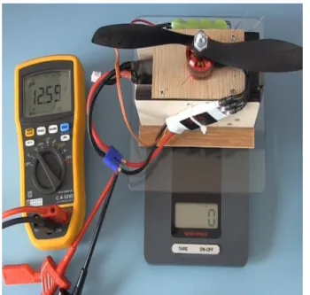
Fig. 13. Setup for observation of thrust v/s voltage relation TEST & RESULTS:
Voltage (Volts) Thrust (Grams) 12.58V 0 12.52V 262 11.56V 227 11.55V 221 11.03V 205 10.47V 186 9.90V 173 9.87V 170
Table. 3. Observation table for thrust v/s voltage measurement
Initially, the motor was off with full scale terminal voltage of 12.58V. As soon as it was fed with 1500µs pulse the terminal voltage decreased to 12.52V. Afterwards, as the battery kept on draining the thrust too keep on decreasing. Graph of thrust v/s voltage:
9.5 10.0 10.5 11.0 11.5 12.0 12.5 160 180 200 220 240 260 Thr ust (Grams ) Voltage (Volts)
Thus the thrust decreases with the draining out of the LiPo battery with time.
IX. MODULEBASEDAPPLICATIONS
1. Remote Sensing Applications.
2. Applications in the Domain of Disaster Monitoring, namely Forest Fires.
3. Military Applications.
4. Harmful gas sensing where human cannot go. 5. Defence, Security and Surveillance.
6. Inspection and Surveillances in Nuclear Power Plants. 7. Spy work & Anti-terrorism application.
8. Pesticide sprinkling.
Fig. 14. Different modules and their corresponding different Quadcopter
Based on the weight lifting calculations we can use our single economical Quadcopter to lift these different modules satisfying the weight lifting criteria.
X. CONCLUSION
Our research work yielded a successful development of Arduino based Quadcopter with high weight lifting capacity and also it produced a cheaper and affordable Quadcopter which can be easily made from shelf components.
This development platform can be used as a low cost alternative to many applications like pesticide sprinkling, end to end delivery within the transmitter’s RF range, surveillance in defence and other sensitive places, mapping through remote sensing, etc. with very level of precision. The live video transmission through IP based connection can be used to generate 2D map of any area using MATLAB.
ACKNOWLEDGMENT
We are extremely delighted to thank J. Brokking for making the project YMFC-3D available on YouTube. We have tried our best in extending his work at our level. Also we are thankful to our college L.D. College of Engineering for providing us such a beautiful platform for making our development a verity. We also acknowledge our team spirit in writing this research paper and accomplishing the task of building a Quadcopter in the final year of our engineering.
REFERENCES
[1] Prabhjot Singh Sandhu, “Development of ISR for Quadcopter,” International Journal of Research in Engineering Technology (IJRET), vol. 03,Issue 04, pp. 185-186, April 2014.
[2] Sandeeep Khajure, Vaibhav Surwade, Vivek Badak, “Quadcopter Design and Fabrication,” International Advance Research Journal in Science, Engineering and Technology (IARJSET), vol. 3, Issue 2, February 2016.
[3] Quadcopter Dynamics, Simulation, and Control, January 26,2010. [4] http://www.atmel.com/ATmega/PA/88A/PA/168A/PA/328/P.pdf [5] http://www.st.com/resource/en/datasheet/l3gd20.pdf [6] https://www.arduino.cc/en/Guide/Introduction [7] http://shodhganga.inflibnet.ac.in/bitstream/10603/16450/7/07_chapt er%25202.pdf BIOGRAPHIES
Anuragsingh Rajpoot studied
Electronics and Communication Engineering from July-2012 to June-2016 at L D College of Engineering, Ahmedabad-380015. His research interest lies in the communication engineering, Radar and Navigational aids and equipments, Digital Signal Processing and in antennas and wave propagation.
Namrata Gadanistudied Electronics
and Communication Engineering from July-2012 to June-2016 at L D College of Engineering, Ahmedabad-380015. His research interest lies in power electronics, communication, astronomy and astrophysics, antennas designing and wave propagation, and image processing.
Sagar Kalathiastudied Electronics and
Communication Engineering from July-2012 to June-2016 at L D College of Engineering, Ahmedabad-380015. His research interest lies in wireless communications, internet of things (IOT) and micro-controller based applications along with data science and analysis.