HAL Id: cea-02509713
https://hal-cea.archives-ouvertes.fr/cea-02509713
Submitted on 17 Mar 2020
HAL is a multi-disciplinary open access
archive for the deposit and dissemination of
sci-entific research documents, whether they are
pub-lished or not. The documents may come from
teaching and research institutions in France or
abroad, or from public or private research centers.
L’archive ouverte pluridisciplinaire HAL, est
destinée au dépôt et à la diffusion de documents
scientifiques de niveau recherche, publiés ou non,
émanant des établissements d’enseignement et de
recherche français ou étrangers, des laboratoires
publics ou privés.
Modeling of powder die compaction for press cycle
optimization
J.-P. Bayle, V. Reynaud, F. Gobin, C. Brenneis, E. Tronche, C. Ferry, V.
Royet
To cite this version:
J.-P. Bayle, V. Reynaud, F. Gobin, C. Brenneis, E. Tronche, et al.. Modeling of powder die
com-paction for press cycle optimization. TOP FUEL 2015 - Reactor Full Performance, Sep 2015, Zurich,
Switzerland. �cea-02509713�
Modelling of powder die compaction for press cycle
optimization
J-P. Bayle
a*, V. Reynaud
e, F. Gobin
a, C. Brenneis
a, E. Tronche
a, C. Ferry
a, V. Royet
a aCEA, DEN, DTEC, SDTC, 30207 Bagnols/Cèze, France e
Champalle company, 151 rue Ampère ZI Les Bruyères 01960 PERONNAS, France
*
Corresponding author. Tel.: +33 4 66791890; Email address: [email protected] (J-P. Bayle)1.Abstract
A new electromechanical press for fuel pellet manufacturing was built last year in partnership between CEA-Marcoule and ChampalleAlcen. This press was developed to shape pellets in a hot cell via remote handling. It has been qualified to show its robustness and to optimize the compaction cycle, thus obtaining a better sintered pellet profile and limiting damage. We will show you how 400 annular pellets have been products with good geometry’s parameters, based on press settings management. This results are due to according good phenomenological pressing knowledge with Finite Element Modeling calculation. Therefore, during die pressing, a modification in the punch displacement sequence induces fluctuation in the axial distribution of frictional forces. The green pellet stress and density gradients are based on these frictional forces between powder and tool, and between grains in the powder, influencing the shape of the pellet after sintering. The pellet shape and diameter tolerances must be minimized to avoid the need for grinding operations. To find the best parameters for the press settings, which enable optimization, FEM calculations were used and different compaction models compared to give the best calculation/physical trial comparisons. These simulations were then used to predict the impact of different parameters when there is a change in the type of powder and the pellet size, or when the behavior of the press changes during the compaction time. In 2016, it is planned to set up the press in a glove box for UO2 manufacturing qualification based on our simulation methodology, before actual hot cell trials in the future.
HIGHLIGHTS
• 10 tons electromechanical nuclear press for fuel manufacturing in hot cell,
• Modelling of powder die compaction,
• Compaction cycle optimization for net shape pellets,
• Cam-Clay, Drucker-Prager cap model, Net-shape
GRAPHICAL ABSTRACT
1.Introduction
The electronuclear closed fuel cycle chosen by France plans the reprocessing of spent fuel and will enable natural uranium resource saving, as well as a reduction in the volume of wastes and their toxicity compared with the choice of direct storage (once-through cycle). The nuclear waste from spent fuel is classified depending on its activity and half-life. The High Activity (HA) waste represents more than 95% of the total radioactivity of French nuclear waste. The liquid extraction process called PUREX enables the Minor Actinides (MAs) to be separated from the Fission Products (FP) in HA waste. The advanced management of the MAs is a goal for the transmutation envisaged in 4th generation reactors or in specially-dedicated reactors. Two approaches to MA transmutation in fast breeder reactors (FBRs) are envisaged, i.e. homogeneous and heterogeneous recycling. The heterogeneous mode consists in concentrating the MAs in special assemblies located in the periphery of the reactor core. The neutronic impact on the core limits the introduction of a higher quantity of MAs, restricted to 10 to 20%. Materials including Americium (Am) located around the reactor core can be of target type if the MA supports an inert matrix, or else part of a Minor Actinide Bearing Blanket (MABB) if the MAs are directly incorporated into fertile UO2 fuels.
2.Context
The manufacturing of fuel pellets incorporating minor actinides by remote handling in hot cells requires simple, effective operations and robust technologies. Rejects must be minimized, which is harder with higher and higher actinide concentrations. The process of pellet shaping is well known from the literature
[1], [2], [3], [4]. It is generally carried out by uniaxial cold compaction in die to obtain green pellets
(rough pellets from the pressing) with a density about 65% of the theoretical density (th.d). This shaping is then followed by a sintering operation which enables the density to reach 95% of the th.d. At present, the pressing technology used in Atalante hot cells (Marcoule, France) is based on a manual process with a radial opening die, compared to the conventional process of a floating die where a downward movement of the die occurs, enabling the ejection of the pellet. Another process with a fixed die enables pellet ejection by the lower punch which pushes with a pressure support from the upper punch. Damages can be present after the ejection stage if the pressure from the two punches is not coordinated, and these are generally revealed during the sintering stage. They can be worsened by the radiological behavior of the pellet, depending on its composition, and by the manufacturing process. Different defect types occur for sintered pellets, in particular cracks, end-capping and spalling [5]. Cracks can form down the sides of pellets and be longitudinal or lateral, or happen in the ends and sometimes cause a lateral "dishing" in the top of the pellets. Spalling can be found on the sides or the ends. The green pellets can have defects which depend essentially on the level of support pressure during die ejection. Other sources of damage can also be identified in the process of powder shaping [6]. First, the introduction of secondary phases composed of hard inclusions or air pockets leads to an excessive relaxation during ejection, with spalling occurring on the pellets, and to different wear patterns on the internal walls of the die and thus to blocked pellet sliding and to shearing. Secondly, inappropriate press settings for compression level, pressing time, or punch accompanying pressure during ejection can cause damage.
The mechanical stress distribution within pellets during the ejection step influences the surface defects. The mechanical stress induced by the die can be high, in particular at the angle formed by the internal surface of the die when the compact is partially ejected. The stress concentrations are accentuated by springback, which corresponds to the volume expansion of the pellet by relaxation of stress during ejection. Some authors have used digital simulation to estimate the mechanical stresses in pellets during this step. Aydin&Briscoe [1] attempted to determine the residual stress distributions in cylindrical pellets. Their study showed that axial residual tensile stress appears at the extremities of the pellet from the axial stress relaxation stage in die (decompression in die). These stresses are due to the friction forces between the die and the pellet, which block the axial springback when the pressure is released. In their study, neither the pellet slide and release phase nor the interactions with the edge of the die were taken into account, as the radial walls of the die were artificially removed. Jonsen & Hagglad [7] took into account the compaction and the ejection with the real kinematics of ejection. The distribution of the residual stress consolidated by measurements of neutron diffraction show that the pellet edges are submitted to axial compression over a thin layer (200 - 400 µm), and the part below this layer undergoes traction over a thicker zone (600 µm). From these two studies, it is known that residual stresses after ejection are
strongly influenced by the tool shapes and kinematics of ejection. In this context, an ejection performed by a radial die opening is expected to be less damaging. Therefore, this mode of ejection was used for the manufacturing of the minor actinide fuel pellets considered in this study.
Another issue is that minor actinide fuel pellet grinding after sintering must be minimized in order to limit highly radioactive dust. Consequently, geometrical tolerance for the diameter needs to be rather wide, +/-50 µm around nominal values (8-10 mm). Pellet geometrical dimension mastery is necessary in order to obtain "net shape" pellets. It is well known that the pressing stage is critical for the shape of the pellet after sintering. For instance, when uniaxial compaction is performed green densities decrease along the height of the compact from the extremity which was in contact with the moving punch. After sintering, the shrinkage follows the density gradient and a conical shaped pellet is formed. With two mobile punches, a double-conical (hourglass) shaped pellet is obtained. In die compression, the heterogeneous density is due to the friction forces between the powder and the wall of the die, as well as the friction between the grains of the powder [1], [8]. These friction effects have been extensively studied for perfectly cylindrical dies, but never investigated for a specially shaped die. More particularly, the diametrical profile of the die could be designed in order to counterbalance the effect of friction.
3.Objectives
The density gradients obtained in the compact depend on various parameters such as the tool quality, the powder behavior, the compaction cycles, the lubrication type, etc. Because the powders used for nuclear fuel manufacturing are precious, pellet damage must be minimized and a net-shaped pellet which does not require further grinding is necessary. The main objective of this study was to be able to anticipate the demanding manufacturing factors, which can influence the press settings before the production cycle, and then during the manufacturing, to be able to have the shortest possible response time to correct parameters to ensure finished products with stable quality. Consequently, the study firstly concerned the optimization of the fuel manufacturing cycles of an innovative nuclearized press for nuclear fuel manufacturing in a hostile and restricted environment. To meet this need, a capability study of the press is described, with on the first press regulation results in the inactive conditions of a mock-up. An annular geometry pellet with compulsory manufacturing tolerances is taken into account. From the results of the study, simulations are proposed on the basis of previous simulations where the model parameters of the compaction were characterized for various powders. We can thus act on the cycle compaction parameters of the press, on the model parameters of each powder, and on certain friction coefficients depending on the lubricant type.
4.Materials and methods
Powdered material was used in this study. Alumina powder is considered a reference because its behavior is known from the literature [4], and it is widely used in the compaction field of the nuclear community. 4.1.Alumina powder (Al2O3_T195)
Alumina powder was used to guarantee the conformity of the measurement and calculation results which could be compared with those from unpublished works [3]. Furthermore, it will be used to carry out qualification trials for a new nuclearized press currently undergoing testing. The particles are spherical, 50 to 200 µm in diameter. These spheres in turn are composed of 1-10 µ m grains [9]. Main characteristics of the several powders studied are summarized in Tab 1:
Powder Supplier Morphology
Size (µµµµm) Filling density (g.cm-3) Theoretical density (g.cm-3) ETh Theoretical Young’s modulus (GPa) ννννTh Theoretical Poisson’s ratio Al2O3 Ceraquest Spherical 50-200 1.24 3.970 530 0.22 Tab 1: characteristics of Al2O3 powder.
4.2.New nuclear press description and characteristics
One of the fuel manufacturing processes originates in the conventional process of the powder metallurgy industry and enables pellet shaping in dies, followed by sintering. The shaping of the Minor Actinide Bearing Blanket (MABB) pellets is currently done manually in hot cells. Manufacturing Automation and a better control of the shaping parameters were tested during this study, in order to prepare the way for a new automatic nuclear press under a collaboration set up between the CEA and CHAMPALLEALCEN. The minimization of criticality risks is an important goal for MABB pellet manufacturing, and is the main reason why the press is being built to operate without oil, and is completely electromechanical. It is a uniaxial automatic mono-punch simple effect press, with a displacement-piloted die. Its capacity is 10 tons, the maximum height is limited to 1200 mm and the production rate is 1 to 5 cylindrical annular
pellets per minute. Installing the apparatus in an existing hot cell for nuclear fuel production required a modular design and simulation studies, which were carried out using 3D software to show the entry of all modules through the airlock. The objective was to validate the modular units’ ability to be assembled, dismantled and maintained by remote handling techniques. The thirty separate units making up the press had to go through a 240 mm diameter air-lock to enter the hot cell. To be sure the remote handling scenarios were appropriate, virtual reality simulation studies were carried out, taking into account force feedback and inter-connectability between the different units. In parallel, different radiological software checked that the press components’ radiological dimensioning would ensure radiation resistance during operation in a hostile environment. A mock-up simulating the future hot cell and equipped with the real remote handling systems has been built in the CEA/Marcoule HERA facility technological platform, in order to physically test press unit assembly by remote handling, and the apparatus operations. The press, adapted to nuclear conditions, is patented.
The device [9], is a uniaxial mono-punch press, with a single compaction cycle. The upper punch and die are mobile at different velocities and the lower punch is fixed. The die is used for the ejection step with an upper punch pressure support. The hot cell press location imposed the use of an existing hot cell, without modifications or external motors being possible. A transfer of the module units through the 240 mm diameter of the Lacalhene Leaktight Transfer Double Door had to be carried out. To minimize the criticality impact, the use of hydrogenated liquids is not permitted in the hot cell.
This is the main reason why the choice was made of electric motors with transmission systems with a minimum gap, combining rotary and translatory mechanisms for the upper punch and the die. To decrease the height needed, the die motorization was placed to one side and the effort transmitted via a toggle joint to the die plate.
The press production rate is about 4 pellets per minute and its pressure capacity is 10 tons. The base structure has one lower plate. This plate is fixed to a circular rail built into the hot cell floor. The press can therefore be rotated in order to enable access to any of the five main parts as required. The first part includes the rigid frame of the press, consisting of the lower and upper plates connected by 4 guide columns. The plates support respectively the motors of the die and of the upper punch. The lower plate holds the fixed lower punch equipped with a displacement sensor. Between these two plates, the upper punch and the die plates (parts 2 and 3) slide up and down. Plate displacements are monitored by sensors, and the mobile upper punch is also fitted with a force sensor. The powder load system and displacement motor of the filling shoe are set up on the mobile die plate. The filling shoe is moved laterally by an electric motor and a rack system. The powder load system has a tippable powder transfer jar which can be completely connected using remote handling. The press was patented under a CEA and Champalle common patent [9]. The nuclear press have enabled the manufacturing of Al2O3 anular pellets with a 10 mm die diameter in CEA Marcoule mock-up. The AL2O3 powder was used, with a zinc stearate lubrication in the mass measured at 2%.
4.3.Optimization cycle background
The use of the press with slave die displacement (equivalent to a double effect cycle) can enable cycle optimization and operating, in order to reduce the difference between the minimum and maximum pellet diameters. An optimal operating cycle enabling uniform stress distribution throughout the pellet means making the applied and transmitted forces equivalent. The difference between these forces is called ∆. To influence ∆, several parameters were varied in the compaction cycle.
We shown in the previous study [9], the evolution of the measurements of applied and transmitted forces as well as the displacements of the upper punch and the die depending on time during a force piloting. A batch of 3 pellets (1 to 3) was made for each set of parameters (serial 1 to 6), (ex: 308S=Serial 3, Number of pellet 08, S for sintered, letter G is for green pellet). The parameters varied were: die start force (kN), noted SF; the upper punch force slope, noted R, it is the time in seconds to pass from the force at the beginning of compression to the maximal force; the die stroke in mm, noted C, equal to the difference between the position of the height of the powder column and the position of the compression start point; the compaction speed of the die in mm/s, noted Vm. Constants are: the force at the beginning of compression is set (punch) at 2.5 kN; the compressive force (punch) is 46 kN; time to the compression plateau (punch) is 3 seconds; the decreasing slope (punch) is set at 2.5; the maintaining force (punch) at 0.2 kN; the position of the height of the cavity (die) at 25 mm; the extraction speed is set (die) at 9 mm/s.
The interest of using a pressing cycle enabling control of the stress gradients in order to master pellet geometry was mentioned previously. The use of the slave die displacement press (almost double effect) seems preferable to a double effect press, where both punches are mobile. This is because with a mobile die, pellet support pressure given by the upper punch is difficult to manage, which makes the process more complex. It has been shown that having both punches mobile can give the same pressure to both, and minimize and center the shrinkage in the middle of the pellet. With a mobile die, the results are equivalent and the risk of pellet damage during ejection is also minimized. In the sam study, we shown the evolution of the green and sintered pellet diameters depending on the height of the Al2O3 powder. The internal diameter of the die is equal to 10 mm. The pellet springback after ejection is often determined by law ρOut_die=a.ρIn_die+b, [10].
The springback reduce the density gradient. This reduction depending on the evolution of the a parameter, high reduction corresponds to a low parameter a.
The radial pellet springback (φOut_die−φDie) was 1 % under optimal settings for the Al2O3 powder. The shrinkage after sintering is also often determined by the lawφSintered(z)=φGreen(z)−∆δ , [10]. Where ∆δ is the sintered diametral shrinkage. It was 10 % under optimal settings for the Al2O3 powder. The relationship for the average diameter and internal tolerances is shown below. We explained that The the springback and all shrinkages depending on the parameters of the pressing cycle and shown the picture of the green pellets manufactured at the top, and the same pellets after sintering at the bottom. Note that the pellet number is used to record the compaction direction of the pellet, and the side with a number is where the upper punch applied the force.
The average diameter is calculated with:
(
((
)
/
2
)
/ ( Max Min)/2 Min Max Mini Average φ φφ
φ
φ
φ
=
+
−
+ − −The compaction cycle settings for a given powder thus require an optimization of the press setting parameters. For the Al2O3 powder studied, in order to obtain a geometrical tolerance of +/-0.012 mm for a diameter sintered to 9.015 mm, the choice was made of a die start force of 3.5 kN, an increase slope for the upper punch of 5 seconds to increase from 3.5 to 46 kN, a die compression speed of 7 mm/s, a 25 mm die cavity depth, and a compression height of 19 mm which enables a green pellet height to be compacted to 11 mm. These optimal settings meant the best pellet quality was obtained, with a lubricant inside the powder and with a good flowing powder. We can see the bad result of single effect compaction (101, 102, 103) where the die velocity is equal to 0 and the high shrinkage where the stress is low (lower punch). Comparison between experiment and calculation results shows that a good volumetric expansion (springback) and an important difference concerning shrinkage results.
The results of the serial 3 have been used to calculate size of a new tool. The sintered input dimensions of the sintered pellet are given bellow by: Diameter = 8.45 +/-0 .09 mm, hole diameter = 2.2 mm and, height < 12 mm. We have used the same parameters of the press cycle than the serial 3. The die diameter was of 10.000 mm and the sintered pellet diameter was 9.015+/- 0.012 mm. The proportional law is possible for the small gap and the new calculate diameter is 9.370 mm with the high tolerance fixed to +/- 0.005 mm. The needle diameter has been not changed. Two new tools have been built, one with needle and one without needle. We decided to shape 400 pellets with hole and 400 pellets without hole but only hole pellet results are presented in this study. Statistical study has been made like next chapter, the main goal is to determine the capability of the press depending on the tolerances given before.
5.Capability study
5.1.Trials
The capability of the machine is the ability of the apparatus to reach the required input performance. This takes into account the statistical process control and permits a measurement of whether the machine can respect the interval tolerances (defined by the top and bottom targets) given in the specifications.The apparatus concerned in this study is the nuclear press described in chapter 4.2 and the diameter of the pellet (with hole) is 8.45 +/-0. 09 mm. Altogether, 400 pellets were shaped with the regulation parameters given in Tab 2.
Parameters Symbol Value Unit
Die start force SF 3.5 kN
Upper punch force slope R 5 s
Die stroke C 6 mm
Die compaction speed Vm 7 mm/s
Tab 2: Regulation parameters of the cycle press The Fig 1 shows compaction cycle during 400 annular pellet production.
Fig 1: Compaction cycle used to shape annular pellets
The powder density depends on the position of the height of the cavity (25 mm), the die diameter (9.370 mm) and the weight of the pellet (2.180 g). The powder density calculated is about 1.26 g.cm-3. The volume of the powder necessary to make 400 pellets is 0.689 l (1723.10-6 x 400). For information, the capacity of the jar is 0.751 l and 0.374 l between the jar and the die cavity. The pellets were shaped in continuous compaction, and a pathway system was built to keep the order and the direction of the pellet. This order was monitored to check the press variations (drift) and direction, and to see the side where the upper punch applied the force. All the compaction cycles were recorded in the press data base software. The pellets were put into glass tubes containing 37 pellets, see Fig 2.
Fig 2: Press in the mock-up, with conveyor and tubular container of 37 pellets (left), Sintered pellets in the alumina container (100 pellets)
After compaction, each green pellet was measured by laser profilometer (height, and diameter corresponding to height) and weighed with precision scales. A chronological number was written on the side directly in contact with the upper punch. All the pellets (100 per batch) were then placed in an alumina crucible and sintered in a furnace under air. To record the pellet number, photos were taken before and after sintering. The written pellet number disappeared after sintering but the photos enabled the numbers of certain pellets to be remembered. The sintering conditions were 1600°C, with 4 °C/min for the heating up, for a duration set at 4 hours, followed by 2 °C/min for the cooling. The same measurements were carried out on pellets after sintering (height, diameter and weight).
5.2.Results
5.2.1.Annular pellets
Fig 3 shows the evolution of diameters as a function of pellet number. Diameters increase slowly after the middle of the production and are less regular than at the start of the production. After 194 pellets, pellet diameters are more random.
Fig 3: Sintered pellet diameter evolution as a function of pellet number
As shown in Tab 3, the average diameter of the pellets is 8.510 mm, the maximum and minimum diameters are respectively 8.533 mm and 8.487 mm. The project objective was reached, but the diameter of the die must be reduced because the average diameter is still too high.
Φdie (mm) Φsintered (mm)
trial number 308 10.000 9.015 +/-0.012
Objective 8.450 +/-0.090
Results 9.370 +/-0.005 8.510 +/-0.023
Tab 3: Comparison between objective and result diameter, compared to trial number 308 In Fig 4, we have the evolution of the sintered pellet height as a function of pellet number. Like the previous result, the height increased after 194 pellets and the measurement is more random.
Fig 4: Sintered pellet height evolution as a function of pellet number
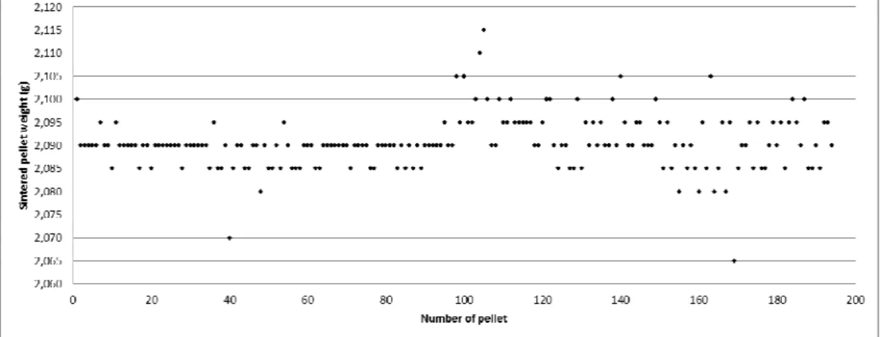
To confirm these results, Fig 5 shows the evolution of weight as a function of pellet number. The random evolution after 194 pellets is the same, and is due to press behavior and not to the sensitivity of the sensor.
Fig 5: Sintered pellet weight evolution as a function of pellet number
The Fig 6 shows the histogram of the sintered pellet diameters. We can see that the distribution is not centred and the asymmetric coefficient is 0.572. The average is 8.508 mm. The maximum is 8.533 and the minimum is 8.490. The standard deviation is 0.0068 and the variance is 4.75. 10-5. The Alfa coefficient of the confidence gap is 0.05. The Cp capability process is 5.03. The performance process coefficients Pp and Ppk are respectively 4.35 and 1.52 and we must conclude that the process is very capable [16].
Fig 6: Histogram of the sintered pellet diameter.
6.Simulations
6.1.Geometrical model and meshing
The geometrical model is an axisymmetric 2D type. It is established based on the powder column, the die and the lower and upper punch. The upper punch and the die are mobile. A connector (equation between 2 nodes) was used to ensure the speed ratio between the upper punch and the die (punch with rigid connection for piloting via a reference node), as shown in Fig 7 (left):
Poinçon supérieur Matrice Poinçon inférieur Colonne de poudre Die Lower punch Filing die Upper punch Raffinement du
maillageRefined mesh
Fig 7: 2D geometrical axisymmetric model (left), Mesh tools (right); greatly improved mesh The punch mesh is relatively large and uniform. That of the powder is also uniform, and a little finer. On the other hand, that of the die is much more refined, as shown in Fig 7 (right), in particular at the rounded corners in touch with the powder where the stress concentrations are situated, and where the generation of residual stress can be high during the pellet ejection springback. It is the sensitive point which must be handled carefully to avoid generating problems of convergence during the calculation.
6.2.Materials and Model
Two different models were taken into account, the Cam-Clay (CC) model [2], [9], [18] and the Drucker-Prager-Cap model (DPC) in the Finite Element Method (FEM) Abaqus® software [2], [17].
6.2.1.Cam-Clay model
Roscoe et al. [11] of Cambridge University first established general relationships of soil behavior based on the theory of elastoplasticity with strain hardening, in the field now described by Cam-Clay Models. These models are based on four main elements: the study of isotropic compression tests, the concept of critical state, a force relation-dilatancy and the rule of normality for plastic strain. In the Cam-Clay Model, the elliptical load surface (plastic potential), in isodensity, is defined in the plan of invariants (P, Q) by the expression ( 1 ) : ( 1 ) ( , , ( ))=( / ( ))2+ ( − C)=0 P V Q M P P P Q P f ρ ε ρ
In this law, P=(σApplied +σRadial)/3is the hydrostatic stress. Q=σApplied −σRadial is deviatoric stress.
) , ,
, ,
( Applied Transmitted Radial
f
M = β µσ σ σ is the internal powder friction coefficient, it characterizes the
Die filling
critical state of the constraints and separates de-densification from densification. It depends on flow index
β, friction coefficient µ, and applied, transmitted and radial stresses.
The pressure PC represents the pellet’s maximum allowable pressure before densification is activated (consolidation pressure). Its value depends on previous load states and mainly on the density. It follows a shape evolution law (2):
(2) dPc/Pc =k.dρ/ρ , hence P V Kappa Lambda e P V C P e P ε ε ) ) 1 ( ( 0 0 . ) ( − + − =
where e0 is the void ratio: e0=(1−
ρ
ref)/ρ
ref.Kappa is the elastic contribution, Lambda the plastic contribution and
ρ
ref is the reference relative density or non-packed relative initial density:ρ
ref =ρ
real/ρ
theo.P0 is the initial consolidation pressure and εVPis the plastic volumetric strain. The relationship between εVP and ρ is :
P V
e ε
ρ
ρ = . −
0 where ρ0 is the initial density.
The plastic strain, or density, becomes the strain hardening variable of the model. It goes through the origin and is centered on the hydrostatic pressure axis.
The elastic and plastic modules, respectively Kappa and Lambda, are taken from isotropic (oedometric) compression tests. In these, the powder is compacted in a die and then changes in powder height H are drawn up as a function of the applied pressure P. Next, the void ratio is drawn up as a function of the P logarithm with:e=n/(1−n), wheren=1−ρ/ρtheo is the powder porosity. The isotropic compression test results give curves e=f(ln σ) which can be considered as lines:
• A blank consolidation curve, called the Lambda curve, which describes the load during the test,
• An unloading-reloading curve, called the kappa curve, which describes the non-linear elastic behavior during the test.
The oedometric test is a normalized test stemming from the study of soil behaviors. It is the curve of loading-unloading, called the K curve, that describes the non-linear elastic behavior during the test. Reference [9] gives oedometric curves for the alumina powder at four pressures, 150, 300, 450 and 600 MPa. From the essential alumina material data, for example (ρth), and essential geometrical tool (d), it is possible to calculate the volume of powder loaded. For example for a mass of 0.410 g, a powder column height (h) of 13.82 mm and a diameter of 5.165 mm, V0 289.73 mm3 is found.
The filling density ρ was then calculated, followed by the n0 porosity and by the void ratio e0, [9].
Two successive versions of the Cam-Clay Model were proposed. The original model enabled a qualitative description of the phenomena observed experimentally, but for paths close to the isotropic compression axis and for low constraint ratios, this model predicted overly-strong deviatoric strains εvP. For that reason, the flow law or Constraint–dilatancy relationship was modified by Burland&Roscoe [11]. The load surface passed from a kernel shape to an ellipse for the modified model. According to [15], other improvements were made to the modified model. To describe the cohesion of the pellet during traction or shear, the load surfaces were moved towards the negative mean pressures.
The porous elastic material law (not linear, isotropic) under Abaqus is expressed according to according to the Abaqus user manual. The hydrostatic stress evolves exponentially, with volumetric deformation (3): (3) − + + + − = ( 0 )exp 1 0 (1 exp( )) el vol el t el t kappa e p p p p ε , with ln( ) 1 ) 1 ( 0 0 − = + + + el el t el t J p p p p e kappa
where Jel -1is the volumetric nominal strain and
ε
volel=
ln(
J
el)
is the volumetric elastic logarithmic strain. ptel is the elastic limit traction stress (= 0 in the case of Cam-Clay) and p0 is the initial pressure when the œdometric test begins. There were not enough points on the elasticated part of the oedometric test, and therefore a position on the part where the elastic return takes place was chosen by making the hypothesis of linear return.This is translated by a straight line to calculate the kappa=0.0675 parameter. A theoretical Poisson’s ratio stemming from data information was also taken, i.e. ν=0.22.
For the strain hardening consideration, another representation is possible in Abaqus. We selected the points on the consolidation pressure evolution curve depending on the plastic volumetric strain, as shown in [9].
The consolidation pressure is the relationship of the force on the pellet section, although strictly speaking it is equal to the geometric average of three stresses (axial, radial and circumferential).
ForεVolPl , it is a function of the Jplastic natural logarithm. With Jtotal=Jelastic*Jplastic, knowing the Jtotal and Jelastic expressions according to respectively (4) and (5), it is possible to calculate the expression of
) ln( plastic Pl Vol = J ε : (4) ln( ) 1 1 0 0 p p e kappa Jelastic + + = (5) 0 0 0 0 0 1 1 ) ( H H V V V V V V V Jtotal ∆ + = ∆ + = ∆ + = =
Where P is the applied pressure, ∆H =H−H0
Finally, besides consolidation pressure points and volumetric plastic strain [9], the code needs the stress ratio corresponding to the M parameter (guiding coefficient of the line passing through the summit of the load line (critical state) in the plan (P, Q)), for which an average value was taken according to the identification of the coefficients [9], (for example M=1.7 for Al2O3), an initial value of the plastic strain (εVolPl0=1.10-5). ϖ is a constant used to modify the shape of the load surface, see Abaqus® user manual. It was taken to be equal to 1 and is the ¥ calibration parameter which controls the load dependence of the 3rd stress invariant. It is generally between 0.8 and 1, and here it was made equal to 1.
On the other hand, the M module is considered as the critical state of the material, as in the previous study with Cast3M® [9], [15], [18]. We had taken ten M values depending on the density, but this possibility was not taken into account in the Abaqus code and will lead to a later improved version.
You can see in Tab 4, the AL2O3 powder Cam-Clay model parameters in Abaqus® FEM Code.
Parameters Type Unit Cam-Clay
m Weight g 0.410
ρth Theoretical density g/cm3 3.9
d Die diameter mm 5.165
h Powder column height mm 13.82
V0 Powder volume in die mm
3
289.73
ρ Powder density in die g/cm3 1.415
n0 Porosity 0.637
e0 Void ratio 1.756
el t
p
Yield stress MPa 00
p
Initial pressure MPa 0.1ν Poisson’s ratio 0.22 0 Vol
ε
Initial volumetric strain 1.10-5 β 1 Κ 1 M 1.7Kappa Elastic coefficient 0.067
) ( VolPl
f
Pc= ε Consolidation
pressure MPa [9]
6.2.2.Drucker-Prager Cap model
The characteristics of the Modified Drucker-Prager/Cap model are:
This model is intended to simulate the constitutive response of cohesive geological materials, It adds a “cap” yield surface to the linear Drucker-Prager model:
o To bind the model in hydrostatic compression,
o To help control volume dilatancy when the material yields in shear.
The elastic response is followed by a non-recoverable response idealized as being plastic, The material is initially isotropic.
The yield behavior depends on the hydrostatic pressure. There are two distinct regions of behavior: On the failure surface, the material is perfectly plastic,
On the cap yield surface it hardens and also stiffens,
The hardening /softening behavior is a function of the volumetric plastic strain.
The yield behavior may be influenced by the magnitude of the intermediate principal stress. The inelastic behavior is generally accompanied by volume changes:
On the failure surface, the material dilates, On the cap surface, it compacts,
At the intersection of these surfaces, the material can yield indefinitely at constant shear stress without changing volume.
Under large stress reversals, the model provides reasonable material response on the cap region. However, on the failure surface region, the model is acceptable only for essential monotonic loading. The material properties can be temperature dependent.
To describe the model, the model can use linear elasticity or nonlinear porous elasticity. It used two main yield surface segments:
A linearly pressure-dependent Drucker-Prager shear failure surface, A compression cap yield surface.
The Drucker-Prager failure surface itself is perfectly plastic (no hardening), but plastic flow on this surface produces an inelastic volume increase, which cause the cap to soften. The Drucker-Prager failure surface is:
( 6 ) FS =t−ptanβ−d=0
Where β is the angle of friction, d is the cohesion of the material, t is the measurement of the deviatoric stress. This allows matching of different stress values in tension and compression in the deviatoric plane. The cap yield surface is:
( 7 )
FC = (P−Pa)2 +[
Rt/(1+α−α/cosβ]
2−R(d+Patanβ)=0Where R is a material parameter that controls the shape of the cap, α is a small number and Pa(εVolPl )is an evolution parameter that represents the volumetric plastic strain driven hardening/softening. The Cap yield surface is elliptical with constant eccentricity in the meridional (p-t) plane. It includes dependence on the third stress invariant in the deviatoric plane and hardens or softens as a function of the volumetric plastic strain (volumetric plastic compaction causes hardening, volumetric plastic dilation causes softening). The hardening/softening law is a user-defined piecewise linear function relating the hydrostatic compression yield stress, Pb and the corresponding volumetric plastic strain εVolPl . The volumetric plastic strain axis in the hardening curve has an arbitrary origin.
0 Pl Vol
ε is the position on this axis corresponding to the state of the material when the analysis begins, thus defining the position of the cap (Pb) at the start of the analysis. The evolution parameter Pa is given as:
) tan 1 ( R β Rd P Pa b + − = . The
parameter a is a small number (typically 0.01 to 0.05) used to define a transition yield surface:
( 8 ) Ft= ((P−Pa)2+
[
t−(1−α/Cosβ)(d+Patanβ]
2−α(d+Patanβ)=0Thus the model provides a smooth intersection between the cap and the failure surfaces. A larger value of
Fig 8: Drucker-Prager load surface
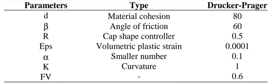
Tab 5 summarizes all Drucker-prager parameters uses in Abaqus® code for Al2O3 powder.
Parameters Type Drucker-Prager
d β R Eps α K FV Material cohesion Angle of friction Cap shape controller Volumetric plastic strain
Smaller number Curvature - 80 60 0.5 0.0001 0.1 1 0.6
Tab 5: Drucker-Prager model parameters in Abaqus® FEM Code for AL2O3 powders
6.3.Geometric model, meshing, loading and boundary conditions
During the simulation, the uniaxial simple effect cycle of shaping with a floating die is composed of a succession of discrete stages, each run in a succession of iterations. At the beginning of the calculation the die is considered to be full of powder, with the upper punch in contact with the powder. At this stage, there is the first step which consists in powder compaction with the upper punch at the speed of 14 mm/s while exercising a push with the die in the same direction as the upper punch but at a more moderate speed, i.e. 10 mm/s. The step is finished when a plateau of a few seconds is reached at 47 kN (600 MPa). The second step consists in pellet ejection by a vertical die withdrawal and the preservation of a support pressure fixed at 11 kN (150 MPa). During this stage pellet radial springback takes place. The third step consists in withdrawal of the upper punch and complete pellet freeing, when the pellet axial springback occurs. The final step involves the sintering process, and creates shrinkage depending on the density gradients generated during the shaping, see Fig 9.
6.4.Friction contact
For the press contact elements, the model used is based on the non-penetration of the two bodies in contact. Abaqus® uses the Lagrange multipliers method. The algorithm imposes the non-penetration condition on the resolution system by adding unknowns to the system. This greatly increases calculation time. The friction is defined as a Coulomb friction: σf = µσr, where σf is the residual stress of friction between the die and the powder which comes to oppose the die load, σr is the resultant radial stress of the powder on the matrix, and µ is the Coulomb’s coefficient. The Coulomb coefficient taken into account in the calculation is equal to 0.094.
6.5.Sintering
As indicated in [9], we used a simple sintering model based on thermal strain to one dimensionα∆T =εth, with α =(ρc/95%ρth)1/3−1. To summarize, for each meshing element of the powder, the green density ρc was calculated with the Cam-Clay model as well as the corresponding α coefficient. Next, the thermal dilation model of the green density map, the α coefficient map and a temperature level (∆T = 1) were entered. Shrinkage was thus calculated. A subroutine was developed in a Piton language in the Abaqus® code to take the sintering step into account.
7.Simulation results, comparisons and discussions
We observed convergence problems during the first calculations, because of the raw curve considerations stemming from the press data acquisition concerning the upper punch load evolution of force as well as the die and needle displacements. This problem was solved by separating compaction and accompaniment into several steps, so as to soften the slope changes.
Another problem of convergence comes from the Cam-Clay model itself, because it cannot represent a tensile stress (no section of the load surface corresponding to the negative hydrostatic pressures). There is thus a 10% failure of convergence in elastic return. Two solutions appeared: either to start again with the modified Cam-clay stemming from calculations carried out in a previous study under Cast3M® [9], taking into account of c (cohesion in the model), or change model and take into account Drucker-Prager's cap model in which the cohesion is considered via the parameters d and β.
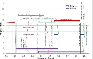
This is presented in Fig 10 where we show the evolution of the pellet height depending on the diameter. The calculation converges better and a better model behavior is seen than for previous calculations, even if the parameters taken into account will need to be further identified. The final goal will be to ensure the calculation results a within the tolerance interval.
To better understand the results, the curves in Fig 10 show different experimental and calculation results. The optimization and capability study conclusions are indicated. For each study, you have the green and sintered pellet diameters and the die diameters obtained by the application of the proportionality law (data shown in green for green pellets and red for sintered pellets). We can see the springback between the die and green pellet, as well as shrinkage between green and sintered pellets. Finally, the calculated green and sintered pellet diameters with Cam-Clay and with Drucker-Prager, used for an optimization study without hole and carried out with the Abaqus® software are shown. The calculation results show the model parameters must be optimized. Drucker-Pragger behavior is better than that of Cam-Clay, as the shape of the sintered pellet is conical. The model behavior at the base of the pellet does not suit the requirements. The height of the sintered pellet must be modified, and the sintered densities are weak. The sintering is too high and must be reduced.
8.Conclusions and Perspectives
The modelling of die powder compaction was studied for press cycle optimization. This optimization enables pellet density gradients and shrinkage after sintering to be minimized for better control of pellet tolerances and to avoid grinding pellets.
Based on the press optimization cycle results (optimization study) from a previous study [9], we were able to minimize the density gradients in the pellet and so to minimize shrinkage after sintering and obtain an annular sintered pellet of 9.015 +/-0.012 mm for a die diameter of 10 mm.
Following thus, in the context of a new project to study cladding issues in fuel manufacturing for the Astrid reactor, we carried out a capability study with the nuclearized press to supply 400 annular pellets meeting the manufacturing constraints of 8.450 +/-0.090 mm for the sintered pellet diameter. The optimization study results were used for a new die sizing, implemented in the capability study by taking into account a simple proportionality law.
In the capability study, good quality results were obtained, with a sintered diameter of 8.510 +/-0.023 mm from a die diameter of 9.370 +/-0.005 mm. The press capability was shown to be satisfactory and no diameter and height drifts were found on the 400 pellets produced.
In parallel, a further objective was to be able to compare the experimental results with results from FEM simulations. This took into account the most realistic compaction model and the press cycles as load or displacement boundary conditions, in order to be as close as possible to experimental conditions. We noticed that the Abaqus® code used does not propose a Cam-Clay model with the cohesion consideration enabling a tensile stress to be represented. Rather than implementing this special feature in the initial model, we opted for a better adapted Drucker-Prager type model, for which the coefficient identification is currently being optimized.
In the future, a similar study is planned for the manufacturing of 400 full pellets (without needle holes) for the same cladding program, with a Drucker-Prager model parameter optimization.
Acknowledgements
We would like to thank the Simulia /Abaqus team for their support and in particular C.Geney. Our thanks also to Champalle and all the LTAP team.
References
[1] Aydin I, Briscoe J, Dimensional variation of die pressed ceramic green compacts, comparison of a FEM with experiment. Journal of the European Ceramic Society 17 (1997) p1201-1212. [2] Brewin PR, Coube O, Doremus P, Tweed JH. Modelling of powder die compaction.
[3] Pizette P, Martin C.L, Delette G, Sornay P, Sans F, Compaction of aggregated ceramic powders: From contact laws to fracture and yield surfaces, Powder technology 198 (2010) 240-250. [4] Pizette P., Martin C.L., Delette G., et al, Journal European ceramic society, vol.33 (2013)
pp.975-984.
[5] Kerboul G, Etude de l’endommagement des produits céramiques crus par émission acoustique, Thèse INSA Lyon-1992.
[6] Zenger DD, Cai H, Handbook of the common cracks in green P/M compacts, Powder Metallurgy Reserch Center, WPI, 1997.
[7] Jonsen P, Haggblad A, Modelling and numerical investigation of the residual stress in a green metal powder body. Powder Technology 155 (2005) p196-208.
[8] Delette G, Sornay Ph, Blancher J. A Finite Element modelling of the pressing of nuclear oxide powders to predict the shape of LWR fuel pellet after die compaction and sintering, AIEA Technical Committee, Brussels, 20-24 October 2003.
[9] Bayle J-Ph et al, Minor actinide bearing blanket manufacturing press and associated material studies for compaction cycle optimization, NuMat 2014 Nuclear Materials conference, 27-30 October 2014, Clearwater Beach, Florida.
[10] Fourcade J, Etude de la mise en forme par pressage uni-axial des poudres de combustible nucleaire, Thèse UMII, 2002.
[11] Pavier E, Caractérisation du comportement d’une poudre de fer pour le procédé de compression en matrice, Thesis INPG/ENSHMG, 1998.
[12] Bonnefoy V, Modélisation du comportement de poudres métalliques et céramiques en compression, Thèse INPG/ENSHMG, 2001.
[13] Gillia O, Modélisation phénoménologique du comportement des matériaux frittants et simulation numérique du frittage industriel de carbure cementé et d’alumine. Thèse INPG, 2000.
[14] Alvain O., Caractérisation, modélisation et simulation numérique de la mise en forme de comprimés MOX par compression et frittage de poudres dures, thèse de doctorat, INPG.
[15] Dellis C et al., PRECAD, A Computer Assisted Design and Modelling Tool for Powder Precision Moulting, HIP’96 Proceeding of the international conference on Hot Isostatic Pressing, 20-22 May 96, Andover, Massachussetts, P75-78.
[16] Desnoyer F., Mémento sur la notion de capabilité, TI, ag1775. [17] ABAQUS® User manual