Publisher’s version / Version de l'éditeur:
Acta Metallurgica, 37, 11, pp. 3107-3118, 1989
READ THESE TERMS AND CONDITIONS CAREFULLY BEFORE USING THIS WEBSITE. https://nrc-publications.canada.ca/eng/copyright
Vous avez des questions? Nous pouvons vous aider. Pour communiquer directement avec un auteur, consultez la première page de la revue dans laquelle son article a été publié afin de trouver ses coordonnées. Si vous n’arrivez pas à les repérer, communiquez avec nous à [email protected].
Questions? Contact the NRC Publications Archive team at
[email protected]. If you wish to email the authors directly, please see the first page of the publication for their contact information.
NRC Publications Archive
Archives des publications du CNRC
This publication could be one of several versions: author’s original, accepted manuscript or the publisher’s version. / La version de cette publication peut être l’une des suivantes : la version prépublication de l’auteur, la version acceptée du manuscrit ou la version de l’éditeur.
Access and use of this website and the material on it are subject to the Terms and Conditions set forth at
Microcrack-enhanced creep in polycrystalline material at elevated
temperature
Sinha, N. K.
https://publications-cnrc.canada.ca/fra/droits
L’accès à ce site Web et l’utilisation de son contenu sont assujettis aux conditions présentées dans le site LISEZ CES CONDITIONS ATTENTIVEMENT AVANT D’UTILISER CE SITE WEB.
NRC Publications Record / Notice d'Archives des publications de CNRC:
https://nrc-publications.canada.ca/eng/view/object/?id=34cbdf43-6d70-4ec9-bd79-554d2adcc31e https://publications-cnrc.canada.ca/fra/voir/objet/?id=34cbdf43-6d70-4ec9-bd79-554d2adcc31eL'HL National Research Conseil national
m
2 1
a
b
+
I
Council Canada de recherche8 Canada 3 .1628
c. 2 Institute for lnstitut de
BLDG
Research in Construction recherche en constructionMicrocrack-Enhanced Creep in
Polycrystalline Material at Elevated
by N.K. SinhaReprinted from Acta Metallur ica Vol.
37.
No.I?.
1989
p.3107-31
18
(IRC Paper No.
1628)
NRCC
31 061
ANALYZED
I N R C-
CISTII R C
L I B R A R Y
This paper is being distributed in reprint form by the Institute for
Research in Construction.
Alist of building practice and research
publications available from the Institute may be obtained by writing
tothe Publications Section, Institute for Research in Construction,
National Research Council of Canada, Ottawa, Ontario, KIA 0R6.
Ce document est distribu6 sous forme de
tiri-&partpar l11nstitut de
recherche en consuuction. On peut obtenir une liste des publications de
171nstitut portant sur les
techniquesou les recherches en matibre de
bstiment en tcrivant
illa Section des publications, Institut de recherche
en construction-
f!!wk----'-----
4 t t a w a
3108 SINHA: MICROCRACK-ENHANCED CREEP IN POLYCRYSTALLINE MATERIALS N E z 2 1 d o B
-
ICE. 0.96 T m (-10°C) 0.5rnm, 0 . 2 ~ l o 4 E (1.9MN . rn.2 ) I I ! I-
U1 . W I I I I ' 0 . ~ 0 0 116 2 . ' U L 3.'2 410 4'8 5.'6 6.'4 7 . 2CREEP TIME, S, lo3
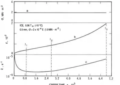
Fig. 1. Strain and strain rate histories for a constant stress loading condition (calculated using theory
developed). I
be judged not only on its compatibility with the response at elevated temperatures is still in its
Monkman-Grant [I] type relation but also on its infancy. It is extremely difficult to measure at 1
ability to describe the entire creep curve, preferably high temperatures even the few basic properties that
the transient range and the beginning of the tertiary are known to play dominant roles [6]. Macroscale
,
stage. strain and microscale defects such as dislocations,
For moderate stresses relevant to many engineering spheroidal voids or cavities, cracks and solid or liquid
1
applications, a > 1 x E, where E is the Young's inclusions fall into this category, and these are only I
modulus, the deformation properties at temperatures a few of the microstructural variables that describe greater than about 0.4 T,, where T, is the melting the state of the body as the process of deformation point in Kelvin, are affected by a grain-boundary progresses [7, 81. Microdefects may already exist in sliding mechanism and wedge type microcracks [2,3] the body and multiply, or they may form during that develop at or are associated with the grain further deformation. Efforts to develop constitutive boundaries (Fig. 2). The enhancement of creep rate equations based on the state variables [5,9-121 have by these micromechanisms will be considered. It will met with limited success. A more refined system of be shown that the failure time based on time t, to equations would be required, in principle, to account
reach i, and the above criteria can be modelled quite for the various microstructural parameters for such a
simply. In addition to the usual external variables of presentation. Thus
stress, time and temperature, the theory considers
i = i(a, t, T, V,)
two internal variables: grain size, and the microcracks (2)
that develop during loading. V, = V,(a, t, T,. . .) (3)
where V, represents other internal and external vari- ables that could be influenced by a, t and T. Expres-
BASIS OF ANALYSIS sions giving the dependence of creep rate on
microstructural variables and equations of state are For a material with a given texture and fabric, required. This paper will focus specifically on how
deformation is macroscopically dependent on strain creep rate is affected by grain size and microcracking
rate. Creep rate has been observed depend On activity during deformation. A generalization of the
stress, time (or strain) and temperature. A above relations to rnultiaxial stresses can only be
consequence of this dependency is the development of made if one has a good of general
constitutive equations of the general form behaviour under uniaxial stress conditions.
i = i ( a , t or 6,T). (1) Close examination of Fig. 2(a-d) reveals that crack
size is directly dependent on grain size. Grain size
A refined equation would be one must therefore be incorporated into the constitutive
that incorporates the state of the material [4] and the
equation if the effect of damage due to microcracks
of loading. Ideally, the state a (either present initially or nucleated during deforma-
body is characterized by ''all" the properties of tion)
and variation in the grain structure are to be the body, but this is impracticable because the pro- considered
cesses under discussion are all thermodynamically
3110 SINHA: MICROCRACK-ENHANCED CREEP IN POLYCRYSTALLINE MATERIALS
where N represents the crack or void density.
Equation (4b) reflects the fact that the initial grain size, d, could change during deformation because of the formation of tilt and small-angle boundaries [Fig. 2(c)], grain-boundary migrations, cell or sub- grain formation [Fig. 2(d, e)] and dynamic recrystal- lization. This change in the texture depends not only on a, t and T (and the initial grain-size distribution, grain orientation, pre-existing flaws, dislocation den- sity, etc.), but also on subsequent cracking activities and the associated effect of dilatation that induces local triaxial situations and heterogeneous defor- mation. In order to simplify, grain size, d, will be assumed constant and equal to the initial size in the theory to be presented.
The question remains however: how to formulate equation (4c) for N, and how to introduce the effect of grain size and grain-size dependent cracks and their density on the creep rate in equation (4a)? Simple explicit forms of equations (4a) and (4c) will be developed to this end.
HIGH TEMPERATURE CREEP RATE
Most investigations, both experimental and theor- etical, of high temperature creep phenomena have concentrated on quantifying the steady-state con- dition that occurs during period t, to t, (Fig. 1). A fair degree of understanding of steady-state creep rate (also referred to as secondary or minimum creep rate)--to be called "viscous creep rate," i , , in this
paper-has been developed for low and intermediate
stress levels, a < 1 x E. The strain rate is
dominated by grain-boundary diffusion for
a < 1 x lop5 E. It is controlled by the mobility of
dislocations in the range 1 x E
5 a
< 1 x Eand may be described by a quasi-empirical equation of the form [13, 141
EbD a " ( " = A
+
(E)
where A and n are constants, b is the Burger's vector, D, is the lattice self-diffusion coefficient, and k is Boltzman's constant. An improved version of equation (5) includes an additional term for pipe diffusion along the dislocation cores, invoking a low temperature mechanism [15]. It fits the experimental results on minimum creep rate better in the moderate
stress range up to 1 x E. Equation (5) bears
close resemblance to the following empirical relation, known popularly as "the power law"
where L,, is the viscous creep rate for the reference or unit stress, a,,, and AH is the activation energy for creep.
In spite of the well established Hall [16] and Petch [17] relation for low temperature, which gives the lower yield point as inversely proportional to the square root of grain size, equations (5) and (6) contain no grain size effect. The intragranular slip mechanism, which is grain-size independent, is the basis of equations like type (5), and the value of the constants can be adjusted to fit well with the empiri- cal relations of type (6) or its improved version, expressed as a sinh function [18]. The argument against any grain size effect is the observation that creep in the grain matrix occurs at all stress levels at high temperatures (primarily because non-elastic strain can readily be detected) and the concept of a yield stress does not apply. This low-temperature concept of a yield stress, however, is now undergoing re-examination [19]. An example of the non-appli- cability of the Hall-Petch relation to the tensile strength of an austenitic stainless steel at high tem- peratures was discussed by Crussard and Tarnhankar
POI.
Equations (5) and (6), moreover, provide neither information on creep rate during the period t = 0 to t = t, (Fig. l), an important range in the service life of structural components, nor any information on the duration, t , to t , , of the steady-state period that is
known to depend on a and T, and therefore no
indication of the onset of accelerating creep. Additionally, these equations do not clarify the kinet- ics of damage or the effect of damage due to the microcracking activities acknowledged at these stress levels. The effect of grain size is significant, since grain boundaries act as barriers to dislocations, whether gliding or climbing, and there are more boundaries in fine-grained than in coarse-grained material.
At low stresses viscous flow occurs in the grain - matrix, inducing no macroscopic volumetric strain; a continuity in the microstructure is maintained during deformation without any development of voids. While this occurs at stresses < 1 x E and small strains (where grain-boundary diffusion also plays an important role), it cannot be assumed valid at moder- ate to high stresses. Cavities and cracks induce volu- metric change, and pure (macroscopically speaking) viscous flow does not occur without being accom- panied by the strain caused by the voids (change in volume). Experimental data compiled on metals by Miller and Langdon [21] indicate that the total cavity volume fraction rarely exceeds 1%. Volumetric strain induced by the formation of voids is indeed very small (Appendix A), and contributions (due to voids) to the total strain may not be noticed or measured readily in most cases [22]. Cavities and cracks, how- ever, have a profound effect on the redistribution of internal stresses and subsequent creep in the matrix (see Appendix A). In fact, even in materials that exhibit superplasticity, the earlier theory that cavities do not form during superplastic deformation [23] is no longer valid; the problem of cavitation failure in superplastic materials has become significant [24].
SINHA: MICROCRACK-ENHANCED CREEP IN POLYCRYSTALLINE MATERIALS 3111
Consequently, steady-state flow (in the classical sense) does not occur at levels of stress of engineering concern; there is only a minimum creep rate period. It is therefore important to make a clear distinction between viscous creep rate, which occurs all the time (along with other mechanisms) during creep loading, and minimum creep rate, which occurs at a specific time:
1. Viscous creep rate, i,, is the "minimum" value of the grain matrix creep rate, but the "minimum" rate, in, may not be equal to the viscous creep rate.
2. Viscous creep occurs continuously during creep, but the minimum creep rate occurs at a specific time for a given loading condition.
PRIMARY CREEP
Experimental observations by Crussard and Tamhankar [20] on the creep rate of austenitic stain- less steel at temperatures of 923-1173 K, those of Garofalo et al. [25] on an iron-base austenitic alloy at 977 K, plus those of Barrett et al. [26] on copper, and of Malakondaiah and Rama Rao [27] on titanium provide ample evidence that creep properties during the transient period (t < t,) must depend on grain size; further, they indicate that fine-grained material creeps more rapidly than its coarse-grained counter- part during this early creep period. Bird et al. [13] suggested, though qualitatively, that the observed increase in creep rate with decreasing grain size could be due to the increasing contributions of grain- boundary sliding to the overall creep rate. Quantita- tive support for this idea has been provided by Sinha [28]. After extensive review of experimental data on metals, alloys, and non-metals such as ceramics and ice, Sinha [28] hypothesized that the transient creep is associated with the delayed-elastic effect. He showed, further, that the delayed-elastic effect is associated with the grain-boundary sliding phenom- enon and that both mechanisms have the same activation energy as the overall creep respopse. For
conditions where Nabarro-Herring, Coble, or
Ashby-Verrall [29] types of diffusion creep are not dominant and where the dislocation motion is the
a constant (- lln) and s is the stress exponent for grain-boundary sliding displacement.
Equation (8) has been shown by Ashby and Duval [30] to agree closely, up to the minimum creep rate, with recent experimental observations on poiycrys- talline ice carried out by Jacka [31]. It describes the overall creep rate as a decay function of time and the temperature effect as obtained from the activation energy [281. It does not show, however, any accelerat- ing creep.
CRACKING ACTIVITY DURING CREEP It has been shown that the first grain-facet size cracks form in a polycrystalline material when the average grain-boundary sliding (gbs) displacement, 2, reaches a critical value, 2, [32, 331. Direct experimen- tal support For this concept comes from Morris and Harries [34], who studied type 316 austenitic stainless steel at 898 K. Experimental results on copper bicrys-
tals by Watanabe [35] also provide support, although bicrystal results cannot, strictly speaking, be directly applied to polycrystalline materials. The lbrrnation of subsequent cracks is predicted on the basis of grain- boundary sliding displacement in excess of the critical gbs displacement [36], giving
N = N, [exp{$ (2 - f ,)} - 11 (9) where N, is the crack density for (the first cracks) and J/ is a constant; negative values of N are con- sidered to be equivalent to no cracks. In equation (9)
f is given as
where id i s given by the first term in equation (8) and K (assumed to be 1) is a constant arising from the equation of proportionality between gbs strain and average gbs displacement. Equation (10) gives a minimum stress, a,, for creep cracking as the stress for which 2, is reached at t = K
a, = E ( E , / c l dl )Iis. (1 1) rate controlling mechanism, the overall creep rate
As the lattice elastic constants and the fracture
(during the early primary creep period) is given by the surface energy depend on temperature, f, and hence
sum of the delayed-elastic strain rate, id, and the
a, and N depend on temperature. substitution of 2 viscous strain rate, i, [28]
from eauation (10) in equation (9) gives . . i = i ( a , t , T , d ) = i , ( a , t , T , d ) + i , ( a , T ) . (7)
At T = constant, equation (7) may be given ex- N =. {erp[l(+
(:I
plicitly as
x ( 1 - exp[ - (a, t)b]) - f,
& = - c ' d l b ( a T t ) b ( ~ ) ' e x p [ - ( a , t ) b l + i , td
where c, is a constant corresponding to the unit grain CRACK ENHANCED CREEP
size, dl (= 1 m), E is the Young's modulus given by
the lattice elastic constants, a, is the inverse relax- Each crack intensifies the matrix creep rate and the ation time corresponding to the temperature T, b is overall effect depends a great deal on the geometry of
3112 SINHA: MICROCRACK-ENHANCED CREEP IN POLYCRYSTALLINE MATERIALS
these openings. The simplest form of cracks are DISCUSSION
planar in geometry, having one dimension infinitely
larger than the other. For dilute concentrations of An essential element of the above presentation is non-interacting, long narrow cracks oriented with the emphasis assigned to mechanisms that are gener- their major planes perpendicular to a uniaxially- ally believed to play an important but not dominant applied tensile load, and for materials obeying power role at elevated temperatures. Grain-boundary slid- law viscous flow, the enhanced creep rate at a con- ing and the associated accommodation processes stant temperature, i,, following Weertman [37] and have been shown to generate grain-size dependent equation (6), is given by and decreasing creep rate with time during the pre-
minimum creep rate period. It is this mechanism
'
i,=i,(l + 2 7 ~ N a ~ n ' / ~ )(3
- (13) again that is shown to be responsible for generatingintergranular cracks that enhance the matrix creep where N is the numbert of cracks that cross a unit rate and lead to the tertiary stage. The general cross-sectional area oriented perpendicular to the characteristics of a typical creep curve are shown to plane of the cracks and, all the cracks are assumed to be governed by the gbs mechanism. In view of this, have the same size, with width of 2a. The condition the overall creep curve may be thought of as a for non-interaction is defined by a 2 N << 1. response curve generated by modulating the effect of If the cracks are assumed to be the same size as the processes associated with the intergranular those of the grain facets and if the cross-sectional mechanisms. Questions remain however: How well geometry of the grains is assumed to be hexagonal do equations (16) and (12) describe the usual macro- [Fig. 2(a, b)], then the crack size, 2a, can be expressed scopically observed creep rates? Can they be used in in terms of the grain diameter, d, according to a predictive manner?
In addressing these problems it is necessary that the
II
a2=-
2 4 f i d2 (14)
material constants are known or that they can be estimated from the available experimental data, but where d is the diameter of a circle having the same it is not an easy task owing to the numbers involved. area as the average cross-sectional area of the grains. Leaving aside the unit dimensions, namely dl, a,,
Substitution of a 2 from equation (14) in equation (13) Nc and K (= 1, assumed), there are nine unknown
gives material constants in equations (16) and (12) to be
determined.
7L
iVC = Eva 1
+
-.
(
12JJ Nd2n 11')(:I.
(1 5 )The value of E is known for most materials, and in any case can be obtained easily using seismic Replacing the second term in equation (8) by the As grain-bOundary is, strictly
right side of equation (15), creep rate incorporating intragranular processes
crack enhancement is obtained (because of the accommodations required at grain corners and imperfections at the boundaries), b is
.
c ~ d l b€ = - (aT t
lb
(i)
expi - (aT r ) b ~ related to n. It has been shown by Sinha [38] that fortd ice b = lln, a value that has also been used recently
by Ashby and Duval [30]. Whether this simple
n 2 relation applies to other materials remains to be seen.
+.Go
(
I+- 12JjNd2n"')(:]'
(I6) In any case, it may be assumed that b can be estimated from n. This leaves seven unknown con- As the first term is a decay function of time, stants to be determined from creep tests.equation (16) predicts a decelerating creep rate lead- The values of i, and n can be determined from the ing to a steady-state or viscous creep rate in a virgin steady-state creep rates or preferably from the material, provided a < a,. For a > am where cracks measured permanent strain [38] after unloading, pro- form and multiply during deformation, as given by vided (1) that the tests are carried out for a < a, to equation (12), the second term in equation (16) avoid any effect of microcracking, and (2) that some contributes an increasing creep rate with time after consideration has been given to avoiding test con- the onset of cracking activities. The opposite effects ditions (not too low a stress or too fine-grained a of the two terms in equation (16) lead to a minimum material) dominated by other mechanisms such as the creep rate, followed by an accelerating or tertiary formation of rounded cavities [39] or grain-boundary stage. Equations (16) and (12), therefore, describe diffusion [27]. The value of a, can readily be deter- both strain rate and damage (crack density) in a mined at the required temperature by obtaining the polycrystalline material undergoing creep. It should relaxation time from the strain recovery on unloading be mentioned that further refinements can be made after constant stress tests, provided conditions (1) and by introducing the effect of the cracks on the elastic (2) are met or that loading times are less than those components, the effect of cracks in the dilatation, for the onset of cracking activity for a > a,.
grain size and hence crack size distribution, the Once a, is known, c, and s can be estimated from change in grain size and formation of subgrains, etc. either the strain recovery curve or the transient part
SINHA: MICROCRACK-ENHANCED CREEP IN POLYCRYSTALLINE MATERIALS 3113
CREEP TIME, s
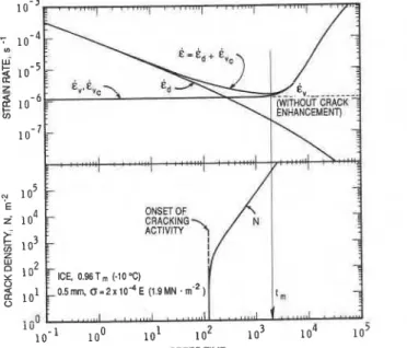
Fig. 3. Computed strain rates and cracking activity during creep for the strain history given in Fig. 1 .
of the forward creep. Alternatively, grain-boundary sliding can be measured for the determination of c, and s. Determination of x, and $ entails consider- able difficulties, requiring metallographical studies [33-351. Acoustic emission (AE) techniques are now well developed and can be used, provided interpret- ation of AE data is made in conjunction with micro- structural investigations (see Appendix A).
Considerable progress has been made in the field of ice mechanics with regard to determining material constants at high temperatures. Those available for ice provide sufficient information to permit calcu- lations and to demonstrate the applicability of the theory to polycrystalline materials in general. The following calculations make use of equations (16) and (12) and the creep constants for ice given by Sinha [28] plus values of x,, N, and $ [33, 361.
The dependence of the components and the total
strain rates in ice on time at 0.96 T, (- 10°C) for a given grain size is shown in Fig. 3; creep strain for this example is indicated in Fig. 1. Note that id dominates the overall creep rate during the transient period, whereas crack-enhanced viscous creep dominates the tertiary regime. Although the cracks start to form rather early in the transient regime, their enhance- ment effects on the average matrix creep rate can be detected only after some time has elapsed following the onset of cracking activity. Note also in Fig. 3 the approach of a steady cracking rate as the minimum creep rate is approached.
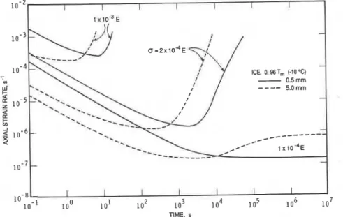
Figure 4 shows the effect of stress on the time dependence of overall creep rate. It should perhaps be pointed out that all the characteristics shown in this figure have been observed in other materials. For
a < a,(% 5 x lop5 E a t 0.96 T,), creep rate decreases
with time and approaches a steady-state condition.
l o - ] l o 0 lo1 l o 2 l o 4 105
CREEP TIME, s
3114 SINHA: MICROCRACK-ENHANCED CREEP IN POLYCRYSTALLINE MATERIALS 1 0 - ~ ~ , , 8 " " ' , , , ,
,
,
, , , , , , , ,,
, , , , - ICE, 0.96 T, (-10 "C) 1-
7 1 0 -5-lo0 lo1 lo2 1 o3 o4 1 o5
TIME, t,. s
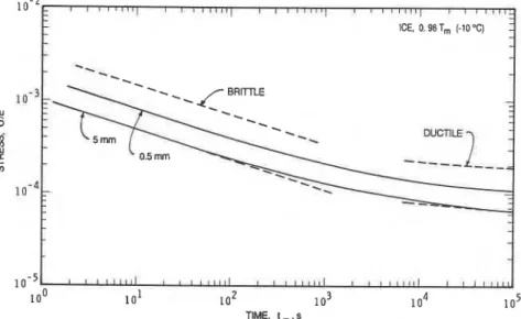
Fig. 5. Stress and grain size dependence of the time to reach minimum creep rate. With increase in stress level, the strain rate passes
through a minimum. The duration of the "secondary stage", at which the strain rate maintains a quasi steady-state value, decreases with increase in stress. The locus of the minima within the family of curves (the broken line in Fig. 4) indicates the dependence of t, on i, and hence a (Fig. 5). This locus is curved, but can be represented approximately, for phenomenological purposes, by two straight lines: one for the higher stresses and one for the lower ones. These, again, have been reported widely and are popularly known as the "Brittle" and "Ductile" ranges, respectively [40]. Each line may be repre- sented as
log t , = constant
-
log i,giving
t,i, = constant. (17)
The inverse proportionality between t, and i, indi- cated by equation (17) bears a striking resemblance to the Monkman and Grant [l] equation for brittle fracture and Hoff's equation for ductile rupture in pure metals and alloys [41].
Since the minimum strain rate, i,, occurs at some finite time when strain rate due to delayed elastic effect is still having a finite value (Fig. 3). i, must be greater than i,. The difference between i, and i , ,
however, depends on stress and is illustrated in Fig. 6, which indicates the increasing deviation of i,
from the straight line (on log-log ordinates) for i,
[equation (6)] as stress increases. This characteristic increase in i, with stress is known as "power-law breakdown" and has been widely reported and em- pirically presented in terms of equation (6) by increas- ing the stress exponent n [42,43] or, alternatively, by the sinh function suggested by Garofalo [18]. In ice with grain size of about 1 mrn and stress up to 9 x lop4 E, a sinh function was used by Barnes et al. [44] to fit their data. They attributed the effect to
dynamic recrystallization without, however, provid- ing any microstructural evidence. Perhaps it should be mentioned, however, that the theoretical curve for fine-grained ice (based on crack-enhanced creep) in Fig. 6 agrees extremely well with their experimental data [ a ] .
Although the minimum strain rate does not show any dependence on grain size at intermediate stresses,
STRESS. Ci/E
Fig. 6. Stress and grain size dependence of the minimum creep rate and the viscous creep rate without crack enhance-
SINHA: MICROCRACK-ENHANCED CREEP IN POLYCRYSTALLINE MATERIALS 3115
I I I I I I I
1
TIME. s
Fig. 7. Theoretical time, stress and grain size dependence of strain rate.
Fig. 6 indicates a pronounced grain size effect at higher stresses, due entirely to higher cracking activ- ity. The minimum strain rate is predicted here as increasing with decrease in grain size. This could therefore provide an alternative explanation for the reappearance of grain-size effect in creep rate at high stresses and temperatures, reported by many investi- gators. Experimental data on an austenitic stainless steel by Garofalo et al. [25] and by Takahashi and Yamane [42] are of particular interest. An increase in i, with decrease in grain size and concomitant increase in i, with a, requiring a sinh function or change in n, indicate that cracking activity must have played an important role in these tests.
A better appreciation of the effect of grain size on creep processes can be made if the time aspect of creep is examined, since time can be measured more accurately than any other variable. A few calculations are given in Fig. 7 to illustrate the effect of grain size and stress on the time dependence of the overall creep rate; it, along with Fig. 5, shows that the time required to reach the minimum creep rate decreases significantly with increase in grain size. For a given stress in the intermediate-to-high stress range the tertiary creep regime and the effect of microcracks should, therefore, become more pronounced as grain size increases. In other words, the theory predicts a decrease in life time with increase in grain
size.
Creepcurves obtained by Mannan and Rodriguez [45] for
Type 316 stainless steel certainly support these pre- dictions. A comparative study of the creep response of ice and steel at elevated temperatures is presented in [46].
Experiments were conducted on ice to test various aspects of the theory. Although a detailed description of this series is outside the scope of the present paper,
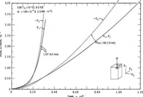
examples are shown in Fig. 8 for transversely
isotropic (S-2) columnar-grained ice with load ap-
plied in the plane of isotropy. In this material, the deformation is essentially two dimensional, E , , E, > 6 ,
(see Appendix A). Note the dilatation effect indicated by the transverse strain, c2, during tertiary creep. The transverse strain rate, i,, increased more rapidly with time than the axial strain rate, i ,
,
as the crack density increased.CONCLUSIONS
1. To avoid much of the confusion that abounds in the literature, a clear distinction has been drawn between viscous creep rate, which occurs continu- ously during load application and is associated with no volumetric strain, and the "secondary" or "mini- mum creep" rate that occurs at a specific time and depends on loading condition.
2. For conditions where grain matrix deformation
is dominated by the mobility of dislocations, mini- mum creep rate at lower stresses or strains where no voids or cracks form is practically independent of grain size and equal to viscous creep rate.
3. Minimum creep rate for deformation caused by microcracking is greater than viscous creep rate. The deviation increases with stress, leading to breakdown in the power law. In the regime of power law breakdown, the minimum creep rate exhibits signifi- cant grain size sensitivity and increases with decrease in grain size.
4. Most obvious changes in creep rate that can be
observed macroscopically during creep, for
1 x E < a < 10-'E, are governed by the inter- granular sliding mechanism and its role in forming cracks and hence the grain matrix creep. The contri- bution of grain-boundary sliding strain to total strain adds to strain rate during the transient period, whereas grain-boundary sliding induced cracks en- hance the matrix deformation and dominate the creep
3116 SINHA: MICROCRACK-ENHANCED CREEP IN POLYCRYSTALLINE MATERIALS
Fig. 8. Constant stress tertiary creep in laboratory grown fine- and coarse-grained ice.
process during tertiary creep. The minimum strain rate occurs as a result of the two effects on the intragranular creep mechanism.
5. Brittle fracture failure (Monkman-Grant equation), ductile rupture failure (Hoff equation), and the transition zone can be formulated o n a
micromechanically based pair of simple relations showing that the time t o the onset of tertiary creep decreases with increase in grain size. A loss in duc- tility for coarse grained material a t higher stresses is predicted.
6. Only after considering micromechanics and per- forming specific tests should values be assigned to the material constants. Cree0 tests should be conducted in conjunction with the measurements of volumetric strain, microcracking activities, creep recovery and metallographic studies.
Acknowledgements-The author is indebted to R. Jerome
for his assistance at all stages of this work. REFERENCES
I . F. C. Monkman and N. J. Grant, Proc. Am. Soc. Test.
Muter. 56, 593 (1956).
2. M. F. Ashby, C. Gandhi and D. M. R. Taplin, Acta
metall. 27, 699 (1979).
3. C. Gandhi and M. F. Ashby, Acta metall. 27, 1565 (1979).
4. G. Scheock, in Mechanical Behavior of Materials at
Elevated Temperatures (edited by J. E. Dorn),
pp. 57-107. McGraw-Hill, New York (1961). 5. R. A. Schapery, in Proc. ZUTAM Symposium, East
Kilbride, U.K., 1968 (edited by B. Boley), pp. 259-285. Springer, Berlin (1970).
6. R. H. Marion, Expl Mech. 18, 134 (1978).
7. J. H. Gittus, in Constitutive Equations in Plasticity (edited by A. S. Argon), pp. 485-548. MIT Press, Cambridge, Mass. (1975).
8. M. F. Ashby and H. J. Frost, in Constitutive Equations
in Plasticity (edited by A. S. Argon), pp. 116-147. MIT
Press, Cambridge, Mass. (1975).
9. L. M. Kachanov, Zzv. AN SSSR, Ofd. Tekhn. Nauk. 8,
26 (1958).
10. D. Krajcinovic and G. U. Fonseka, ASME J. Appl.
Mech. 48, 809415 (1981).
I I. D. Krajcinovic, J. appl. Mech. 50, 355 (1983). 12. S. P. Hannula, M. A. Korhonen and C. Y. Li, Res.
Mechanica 15, 99 (1985).
13. J. E. Bird, A. K. Mukherjee and J. E. Dorn, in
Quantitative Relation Between Properties and Micro-
structures (edited by D. G. Brandon and A. Rosen),
p. 255, Jerusalem Univ. Press, Israel (1969).
14. E. W. Hart, C. Y. Li, H. Yamada and G. L. Wire, in
Constitutive Equations in Plasticity (edited by A. S.
Argon), pp. 149-197. MIT Press, Cambridge, Mass. (1975).
15. H. E. Evans and G. Knowles, in Creep and Fracture
of Engineering Materials and Structures (edited by
B. Wilshire and D. R. J. Owen), p. 169, Pineridge Press, Swansea (1981).
16. E. 0. Hall, Proc. Phys. Soc. B64/747 (1951). 17. N. J. Petch, J. Iron Steel Znst. 174, 25 (1953). 18. G. Garofalo, Fundamentals of Creep and Creep-Fracture
in Metals. Macmillan, New York (1965).
19. G. J. Weng, J. Mech. Phys. Solih 31, 193 (1983). 20. C. Crussard and R. Tamhankar, Trans. Am. Znst. Min.
Engrs 212, 718 (1958).
21. D. A. Miller and T. G. Langdon, MetaN. Trans. A 11A,
955 (1980).
22. R. Raj, Acta metall. 31, 29 (1983).
23. R. H. Johnson, Superplasticity, Metall. Rev. 15, 115 (1970).
24. B. P. Kashyap and A. K. Mukhe qee, Res Mechanica 17,
293 (1986).
25. F. Garofalo, W. F. Domis and F. von Gemmingen,
Trans. Am. Znst. Min. Engrs 230, 1460 (1964).
26. C. R. Barrett, J. L. Lytton and 0 . D. Sherby, Trans.
Am. Inst. Min. Engrs 239, 170 (1967).
27. G. Malakondaiah and P. Rama Rao, Scripta metall. 15,
1107 (1981).
28. N. K. Sinha, Phil. Mag. A 40, 825 (1979).
29. M. F. Ashby and R. A. Verrall, Acta metall. 21, 149 (1973).
SINHA: MICROCRACK-ENHANCED CREEP IN POLYCRYSTALLINE MATERIALS 3117
30. M. F. Ashby and P. Duval, Cold Regions Sci. Tech. 11,
285 (1985).
31. T. H. Jacka, Cold Regions Sci. Tech. 8, 261 (1984).
32. N. K. Sinha, in Deformation and Failure of Granular
Materials (edited by P. M. Vermeer and H. J. Lugar),
Proc. ZUTAM Symp., pp. 323-330. A. A. Balkema, Rotterdam (1982).
33. N. K. Sinha, J. Mater. Sci. 19, 359 (1984).
34. D. G. Morris and D. R. Harries, J. Mater. Sci. 12,1587
(1977).
35. T. Watanabe, Metall. Trans. A 14A, 531 (1983). 36. N. K. Sinha, in Advances in Fracture Research, Proc. 6th
Znt. Con$ on Fracture (ZCF6), Vol. 3, pp. 2295-2302. Pergamon, Oxford (1984).
37. J. Weertman, Trans. Am. Soc. Metals 62, 502 (1969).
38. N. K. Sinha, Exp. Mech. 18, 464 (1978).
39. L. C. Lim, Acta metall. 35, 1663 (1987).
40. F. K. G. Odqvist, Mathematical Theory of Creep and
Creep Rupture, Chap. 10, pp. 131-140. Clarendon, Oxford (1974).
41. N. J. Hoff, J. appl. Mech. 20, 105 (1953).
42. Y. Takahashi and T. Yamane, J. Mater. Sci. 14, 2818
(1979).
43. S. Vagarali and T. G. Langdon, Acta metall. 29, 1969
(1981).
44. P. Barnes, D. Tabor and J. C. F. Walker, Proc. R. Soc.
Ser. A 324, 127 (1971).
45. S. L. Mannan and P. Rodriguez, Metal Sci. 17, 63 (1983).
46. N. K. Sinha, Ice and steel-A comparison of creep
and failure, in Mechanics of Creep Brittle Materials-I
(edited by A. C. F. Cocks and A. R. S. Ponter),
pp. 201-212. Elsevier Appl. Sci., London (1989).
APPENDIX A
Uniaxial constant-load creep tests were carried out on
rectangular specimens of polycrystalline ice 250 x 100 x
50mm; load was applied parallel to the length of the specimens. The ice was made from distilled, de-aerated and deionized water using a special seeding and selection technique [38]. It was pure, bubble-free, transparent, trans- versely isotropic and columnar-grained. The long dimen- sions of the specimens were normal to the length of the grains. A closed-loop servohydraulic test machine (MTS) situated inside a cold room was used to apply load, using the feed-back load control system. To avoid any cracking activity due to load application, the load was applied at a
rather low stress rate of 0.5 M N . m-= s-I. After the desired
full load was reached (in a few seconds), it was maintained constant until the end of the test period. Axial as well as lateral strains in two mutually perpendicular directions were
recorded using three commercially available dispfaoement
gauges (MTS) mounted directly on the specimen by means
of special brackets (made at NRCC) frozen to the specimen
surfaces (Fig. Al). Microcracking activity during creep was
recorded by a microprocessor-based acoustic emissron sys-
tem (AET-5000) and a detector mounted on the specimen.
Cracking activity was also recorded visually using an cvent
marker prirnarsly to identify the awustlc emission (A.E.) characteristics associated with the formation of grain-face1
su7e cracks large enough to be visible.
An exampie o f test results at
-
10°C _fO.luC is shown inFig. A2. This test was continued for a period long enough
to ensure that the tert~ary creep regime was well established
before the specimen was unloaded. Load was removcd
quickly, and creep rccovery was continuously recorded (for
a long tlme) un111 no further m v e r y could be detected.
As the final strain was small, the test results presented can
be assumed to be those for a constant stress test, although strictly speak~ng it was the load that was maintained constant. The main purpose of citing this example is to show
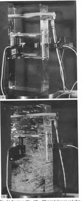
Fig. Al. Specimen (50 x 100 x 250 mm) before (a) and after
(b) the creep test (No. L138) at: u = 1.26 x E
(1.2MN.m-'), T=0.96Tm, d = 6 . 0 m m . the extent of damage due to microcracking, as may be seen in Fig. Al(b), a photograph taken after the test and following full recovery. The quantitative measure of damage within the specimen may be seen in Figs A2 and A3. A
volumetric increase of slightly over 1 % was recorded. This
is certainly due to the dilatation effect of cracking activity that occurred during the creep period.
A detailed presentation of the three-dimensional aspect of the strain field is outside the scope of this paper. It is sufficient to say that microcracking activity plays a major role during tertiary creep at elevated temperatures for loading conditions conducive to the production of cracks.
3118 SINHA: MICROCRACK-ENHANCED CREEP IN POLYCRYSTALLINE MATERIALS
Fig. A2. Dependence of axial, lateral and volumetric strain on time in transversely isotropic (S-2) ice sample (50 x 100 x 250 mm).
I-
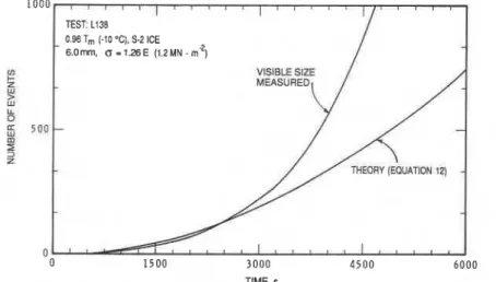
TEST: L138 0.96 T, (-10 ' C ) , S-2 ICE6.0rnrn, 0 = 1 . 2 6 E (1.2MN .in2)
TIME. s
Fig. A3. Time dependence of acoustic emissions with event durations greater than 3 ms (visible or grain facet size).
This is also an opportune moment to mention that the use of columnar-grained ice (which is one of the most common types of ice in nature) adds to the usefulness of the measurements; its transparency assists in clarifying the interpretation of the effects of cracks. As the ice consists of long, pencil-like grains, deformation is essentially two- dimensional during most of the period and the strain is small along x,, the direction parallel to the length of the grains (Fig. A2). As for the cracks, they are long and narrow, with their major planes tending to be in the x,-x, plane; their lengths parallel to the length of the grains along the x, axis; and their widths parallel to the x, axis. A consequence of this geometry is the fact that the dilatation effect of the cracks should be noticed primarily in the lateral strain, t2. An increase in t, and its rate in relation to 6 , , in conjunction
with the rapid change in the volumetric strain, can be seen clearly during the later part of the tertiary creep period, greater than about 3000 s. Figure A3 shows that the theory estimates well the number of visible (grain-facet size) cracks up to about this time. Visible cracks were identified in the specimen, with the A.E. events having event durations greater than about 3 ms.
Analysis of a mid-plane, double-microtomed, thin section at right angles to the length of the columnar grains indicated the average cross-sectional grain diameter (area basis) to be 6.0 mm. Microstructural studies made on this thin section are illustrated in Fig. 2(c, d, e). Figure 2(c) shows intergranular and triple point (boundary) cracks and cavities. Grain boundaries and larger defects, such as tilt boundaries (straight lines) associated with the cracks, rounded cavities and kinks or jogs at the grain boundaries, are revealed by thermal etching. Figure 2(d) illustrates an intra-crystalline crack and two smaller cracks associated with the formation of irregularities at the grain boundaries (double lines correspond to the top and bottom surfaces of the thin section). Large transcrystalline cracks, parallel to the compression axis, and smaller cracks at large angles to the load axis [Fig. 2(e)] are indicative of crack interactions and gross non-uniformity in the stress or strain field devel- oped during the later stages of creep. Smooth grain boundaries and lack of deformation features on the right- hand side of this micrograph show that the formation of the multiple-facet length crack was an efficient means of relieving the local stress concentration sites.