Publisher’s version / Version de l'éditeur:
Vous avez des questions? Nous pouvons vous aider. Pour communiquer directement avec un auteur, consultez la première page de la revue dans laquelle son article a été publié afin de trouver ses coordonnées. Si vous n’arrivez pas à les repérer, communiquez avec nous à PublicationsArchive-ArchivesPublications@nrc-cnrc.gc.ca.
Questions? Contact the NRC Publications Archive team at
PublicationsArchive-ArchivesPublications@nrc-cnrc.gc.ca. If you wish to email the authors directly, please see the first page of the publication for their contact information.
https://publications-cnrc.canada.ca/fra/droits
L’accès à ce site Web et l’utilisation de son contenu sont assujettis aux conditions présentées dans le site LISEZ CES CONDITIONS ATTENTIVEMENT AVANT D’UTILISER CE SITE WEB.
Canadian Acoustics, 19, 2, pp. 11-20, 1991-04
READ THESE TERMS AND CONDITIONS CAREFULLY BEFORE USING THIS WEBSITE. https://nrc-publications.canada.ca/eng/copyright
NRC Publications Archive Record / Notice des Archives des publications du CNRC :
https://nrc-publications.canada.ca/eng/view/object/?id=0179ac5e-07e9-469f-9d1e-1996f3f222b2 https://publications-cnrc.canada.ca/fra/voir/objet/?id=0179ac5e-07e9-469f-9d1e-1996f3f222b2
NRC Publications Archive
Archives des publications du CNRC
This publication could be one of several versions: author’s original, accepted manuscript or the publisher’s version. / La version de cette publication peut être l’une des suivantes : la version prépublication de l’auteur, la version acceptée du manuscrit ou la version de l’éditeur.
Access and use of this website and the material on it are subject to the Terms and Conditions set forth at
Remedial measures for traffic-induced vibrations at a residential site.
Part 2: FEM simulations
S e r
TH1
National Research
Conseil national
1
*I
Council Canada
de
recherches Canada
n.
1 7 0 3
1991
BLDG.
Institute for
Research in
lnstitut de
recherche en
.-
Construction
construction
Remedial Measures for Traffic-Induced
Vibrations at a Residential Site.
Part 2: FEM Simulations
by
M.O. Al-Hunaidi and J.H. Rainer
A M A L Y
ZED
Reprinted from
Canadian Acoustics/Acoustique Canadienne
19 (2), 1991
p.p. 11-20
(IRC Paper No. 1703)
NRCC 32373
.
NRC-
clsrt fI
R
C
L I B R A R Y
.ILl/
15
1991
S ~ B L I O T H $ Q U E
I R C
C N R C-
ICISTCanadian Acoustics 1 Acoustique Canadienne 19(2) 11-20 (1991) Research article 1 Article de recherche
REMEDIAL MEASURES FOR TRAFFIC-INDUCED VIBRATIONS AT A
RESIDENTIAL SITE. PART
2:
FEM SIMULATIONS
M.O. Al-Hunaidi and J.H. Rainer
Institute for Research in Construction, National Research Council of Canada, Ottawa, Ontario KIA OR6
Abstract
This is a companion paper to an experimental investigation, reported earlier, of traffic-induced vibrations at a site where several complaints were lodged by homeowners residing near a roadway. The objective of the previous paper was to investigate experimentally the factors influencing the level of these vibrations and their relative quantitative importance. The present paper reports on the results of the analytical part of the study in which the role of pavement/subbase characteristics, effectiveness of vibration screening by concrete walls and soil improvement were investigated using finite element simulations.
Ce document dCcrit le second volet d'une Ctude, signal& plus tbt, sur les vibrations produites par la circulation; cette Ctude avait kt6 menCe ii la suite de plaintes dCposCes par plusieurs propriCtaires de maisons situCes le long d'une route. Le volet expCrimenta1 de l'Ctude portait sur les facteurs qui influent sur le niveau des vibrations et sur leur importance quantitative relative. Ce document fait Ctat des rksultats du volet analytique, dans lequel les auteurs ont CtudiC, 2 l'aide de simulations par ClCments finis, le r61e de la chausde-couche de fondation, l'efficacit6 du blocage des vibrations au moyen de murs de bCton, ainsi que I'amClioration du sol.
1
INTRODUCTION
Information on the effectiveness of improving pavement/ subbase characteristics to reduce traffic-induced vibrations is scarce. In the one study known to the authors, Tholen (1974) reports that ordinary variations in the nature and thickness of the pavement has negligible influence on the level of traffic-induced vibrations. One would tend to believe, however, that a rigid and massive road structure could be a valid remedy to reduce the level of traffic- induced vibrations.
The purpose of the present study is to investigate the influence of pavement/subbase characteristics on the level of traffic-induced vibrations. Screening of vibrations by a concrete wall and the effect of soil improvement using lime piles were also briefly investigated. The study was performed by means of computer simulations using the finite element method. Such an investigation would be
a theoretically very difficult and experimentally very
expensive. Simulation using the finite element method provides a powerful and economical tool.
This study is the second and a companion part of an investigation of the effectiveness of various remedial measure of traffic-induced vibrations at a residential site (Al-Hunaidi and Rainer 1990). A full description of the site is presented there.
2
MODEL DESCRIPTION
2.1
Source
The source of vibrations is modelled as a steady state harmonic vertical point load applied at the center of the roadway. Although this type of load may not accurately represent the moving source of traffic vibrations (which may be said to fall somewhere between
a
line source and a point source), this approach is considered to provide a sufficiently accurate tool for performing a parametric study of pavement/subbase characteristics as they relate to traffic vibrations. For vibrations originating at a surface crack, the stationary point source is actually quite realistic since it is these vibration components that represent the major part of the induced signal (Al-Hunaidi and Rainer, 1990).2.2 FEM Model
An axisymmetric finite element model is used to simulate the pavemendsubgrade system, unless otherwise noted. Hence, it is implicitly assumed that (i) the subgrade consists of horizontal soil layers and (ii) the propagation pattern of waves generated by a vertical load on the surface of the road is axisymmetric, in spite of the fact that the system is in reality 3-dimensional. The first assumption is usually true for most sites. The second assumption was verified by a set of field experiments.
In these experiments, an electrodynamic shaker was used on a road surface to generate point load vibrations. The induced wave field was measured by a grid of vertical accelerometers placed axisymmetrically with respect to the shaker, as shown in Figure 1. Since the measured ground motion was not purely harmonic due to the presence of ambient vibration at the site, the measured signals were Fourier transformed to obtain the response that corresponds to the frequency of the excitation. For an 8 Hz excitation frequency, the accelerations at measurement stations 1,2,3, 4, and 5 at 10 metres from the shaker (see Figure 1) were 0.7, 1.2, 1.4, 0.9, and 1.3x10-~ (%g), respectively. While there exists some variation in acceleration amplitudes between these stations which are equidistant from the source, from a practical point of view the wave field could be considered sufficiently axisymmetric. The accelerations of measurement stations at 20 and 30 metres, and results of tests with 12 and 16 Hz excitation frequencies also show a similar trend.
The road section under consideration was simulated using the finite element model shown in Figure 2. The model consists of 31 x 31 axisymmetric 4-node elements. The bottom boundary of the model, located at 13.55 m, is fixed to represent a hard (rock) layer. The lateral boundary located at horizontal distance of 13.55 m from the centre line, is a consistent silent boundary (Lysmer and Waas, 1972) which simulates the infinite dimension of the site in the horizontal direction. The maximum element size in the mesh was chosen to satisfy the condition that it is less than 116 the shortest wavelength of interest. The shortest wave length is based on the slowest wave velocity and the
Table 1
Comparison between experimental and FEM results for point source test Force Vc~lical A c c e k h !%
I
Fzlw
h p t i t u P I N fibm,,d FU( 8 173.35 325 x 10" 3.73 xlo"
12 166.69 485x10" 5.03x1U3 16 148.68 8.30 x 10.' 7.75 x 10.'maximum frequency of interest which for the present analysis was taken as 28 Hz. Material behaviour was assumed to be linearly elastic and the analysis was performed in the frequency domain. Frequency response spectra were calculated for points at 0.25, 5.05 and 12.05 metres from the source by applying unit point source load starting with an excitation frequency of 4 Hz and then incrementing it by steps of 1 Hz. Calculations were performed in double precision on an IBM 3090 computer.
2.3 FEM Verification
The accuracy of simulations employing the finite element model shown in Figure 2 was verified by comparing numerical FEM results with those of field measurements. The test problem employed is that of a single oscillating vertical harmonic force acting at the centre of the roadway. An electrodynamic shaker was used in the field test. Vertical acceleration was recorded at a point 5.35 m from the center of the road.
The comparison between numerical and experimental acceleration amplitudes is presented in Table 1 for 8, 12 and 16 Hz excitation frequencies. Although it was not possible
to reproduce exactly the conditions that prevailed in the field, numerical and experimental results show satisfactory agreement.
3
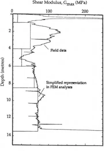
SOIL PROPERTIES
The subsoil investigation consisted of soil sampling, performing Dutch cone penetrometer test, and carrying out resonant column tests in the laboratory. The dynamic shear modulus profile as determined from the Dutch cone penetrometer test is shown in Figure 3 for the location under consideration (note: The dynamic shear modulus is obtained with the cone penetrometer by correlating the results with those of resonant column tests, using undisturbed high quality samples, as well as with cross-hole tests on Champlain Sea clay (Law, 1990)). The bulk soil density was 1.7 ton/m3 and damping ratio from resonant column test was found to be 1.6%. At the time of performing FEM calculations, the damping ratio was not available and it was assumed to be 0.1%. Later verification tests with 1.6% showed only negligible difference of amplitude response at the fundamental frequency of the si~e. Poisson's ralio was
.,
taken as 0.45.Soil layers extended to a depth of 13.5 m, where a firm * layer was encountered by the penetrometer. The soil profile from the surface down is approximately as follows: (i) 1.0 m gravellsand fill. (ii) 4.0 m greybrown stiff weathered - clay, (iii) 8.5 m medium to stiff silty clay. The water table -
I
ROADWAY @\-
LOCATION ELECTRODYNAMIC OF SHAKER0
ACCELEROMETER STATION No. ALL DIMENSIONS ARE IN METRESFigure 1 Axisymmetrical layout of vertical accelerometer stations. P(t) = Poe kV'
(Steady state force)
/SUBBASE
ALL DIMENSIONS ARE IN METRES Figure 2 F i t e element model of roadjsubgrade system
Shear
Modulus,
G,, (MPa) Figure 5. In addition, the following parametric tests wereperformed in conjunction with the modified design:
Figure 3 Shear-modulus profile at test location.
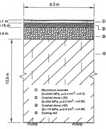
Approximate road dimensions and properties of the existing roadway and a modified design (proposed by an independent consultant) are shown in Figures 4 and 5, respectively.
4
DESCRIPTION OF FEM ANALYSES
The following remedial measures for reducing traffic vibrations were investigated using finite element analyses:
Improving road structure
Screening of waves by a concrete wall Soil improvement
4.1 Effect of road structure
Several FEM tests were performed to evaluate various road designs. Frequency response functions are generated and changes in these functions are taken as indicators of how parameter variation would affect the vibration behaviour of the site. The response spectra of the existing road design were compared with those of the modified design shown in
-
Replace the 10 cm bituminous pavement with 10 cm concrete layer.-
Replace the 10 cm bituminous pavement with 25 cm concrete layer.-
Double the proposed thickness of upper and lower road base.-
Replace the bituminous pavement and upper and -lower base foundations by 65 cm concrete road . (admittedly an impractical extreme case).
4.2
Screening
by
a Concrete
Wall
Screening of ground vibrations by placing a trench in the transmission path of surface waves is known to be an effective measure to reduce ground vibrations (Richart et al, 1970). The trench can be left open or backfilled with a material that provides a sufficient impedance mismatch with the surrounding soil. It was found that when the ratio between an open trench depth and the propagating wavelength is greater than 0.6, the vibrations amplitudes in the screened area are significantly reduced (Segol et al., 1978). A minimal value of 1/3 is usually set for the ratio between the trench depth and wavelength (Le Houdec & Picard, 1988). Contradictory results, however, are reported regarding the effectiveness of stiff obslacles (Scgol cl al., 1978). Therefore, finite element analyses were performed to investigate the effectiveness of a concrete wall to reduce ground vibrations for the site conditions in this study. Two wall depths were considered: 5.0 m and 10.0 m, which correspond to roughly 1/3 and 213 of the longest wavelengths of interest, corresponding to 8 Hz. The concrete wall is 0.5 m wide and is located at 4.05 m from the center of the roadway. For this analysis, a plane strain model was used in order to realistically simulate the wall in the horizontal direction.
4.3
Soil Improvement
Improvement of soil to increase its stiffness using lime piles is reported to be very effective in improving the bearing capacity of the ground (Broms, 1979) as well as reducing ground vibrations induced by dynamic loads (Taniguchi & Okada, 1981). To investigate the possible effects of this -
type of soil improvement on the site under consideration,
-
several finite element analyses were performed. Only the soil under the road is assumed to be improved using 0.4 ' metre diameter piles at 0.9 metre spacing arranged in a rectangular grid. The improved soil's modulus is assumed.
to be 225% of the original modulus. Density is also +assumed to increase by 18%. Calculations were performed
-
for improvement depths of 13.55,8.55 and 6.05 metres. An-
misymmetric FEM model was used.@ Biumhus m m e t e
(E-2500 MPa. p-2.4 I/rn3, v-0.3)
@ Sandhavel subbase
(E-100 MPI, p - 2 . ~ vm3, "-0.35)
0 Existing soil
/
@ BIumlnouomncrote(ES000 MPa, p-2.4 urn3, ~ 4 . 3 )
Crushed stone (-20)
/
(E-250 M P ~ . p-2.0 vm3, v-0.35)@ Crushed etono (-63) (E-176 MPc p-2.0 urn3, v-0.35)
/
Q, Existing soilFigure 4 Existing cross-section of road. Figure 5 Modified design for road section.
5
NUMERICAL RESULTS
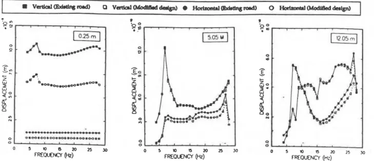
Results of finite element analysis of the road response are graphically presented as frequency response functions at surface points 0.25, 5.05, and 12.05 metres from the source. All results are compared with those of the existing road profile, shown in Figure 4.
5.1 Effect of Road Structure
Comparison between existing design and
modified design
Implementing the modified road design, shown in Figure 5, introduces very little or no reduction in vibration levels at points 5.05 and 12.05 metres from the centre of the road as can be seen from the frequency response functions in Figure 6.
Replacing 10 cm bituminous pavement with 10
cm concrete pavement
The increased rigidity of the pavement layer in the modified design has a negligible effect on the level of vibrations at points away from the road (5.05 and 12.05 m), as can be seen from Figure 7.
Replacing 10 cm bituminous pavement with
25
cm concrete pavement
The 25 cm concrete pavement has a more noticeable reduction of vibration amplitudes than for the case of a 10 cm concrete pavement, especially for the horizontal component. However, close inspection of the results in Figure 8 shows that: (i) the reduction occurs generally at high frequencies, and (ii) the amplitude reduction is more pronounced for points closer to the source (compare the results at 5.05 and 12.05 m). Overall, the reduction in amplitudes is negligible.
Doubling the thickness of the upper and lower
roadway foundations
In the modified road structure, shown in Figure 5, the thicknesses of the upper and lower foundations were increased from 0.15 and 0.4 m to 0.35 and 0.8 m, respectively. Frequency response spectra of this case (not displayed here) show that the amplitude reduction is slightly more than that gained with the original modified design. The amplitude reduction is comparable to that achieved by replacing the asphalt pavement with 25 cm concrete pavement (Figure 8).
5 r O e w n m
FREQUENCY (HZ) O @ FREOUENCY I S N (HZ) ) 2 5 3 0
Figure 6 Frequency response functions of existing road design and modified design 1
'q
:
$;
0 0 9 D-
hS"
Sq I- z I- z W I W I W U oZ*
ais
n 0 n n 0 02
0 5 r O a m n J O 0 ~ Q I S ~ ~ 0J 5 rO O s m 2 s J OFREoCrENCY (Hz) ~REOLIO*=I h) F R E M N C Y (HI)
Figure 7 Effect of replacing 10 cm bituminous pavement with 10 an concrete pavement
-
0 5 1 0 B ? 0 ? 5 Y )
FREOUENCY (Hz)
Using a 65 cm concrete pavement
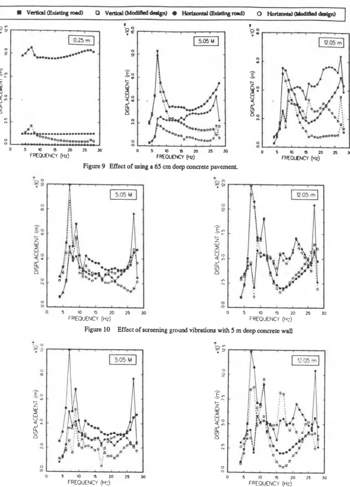
The objective of such an obviously impractical design is to test a hypothetical road structure that is very stiff and massive in comparison with all previous designs so as to detect trends for extreme parameter variations. As can be seen from the response functions of this design, shown in Figure 9, there is a substantial reduction in amplitudes which has not been achieved by any of the previous road structures. The higher the frequency, the higher the reduction. However, amplitude reduction at and close to the fundamental frequency of the roadhubgrade system, which is of primary interest here, is not significant.
5.2
Effect of Screening by Concrete Wall
6
DISCUSSION
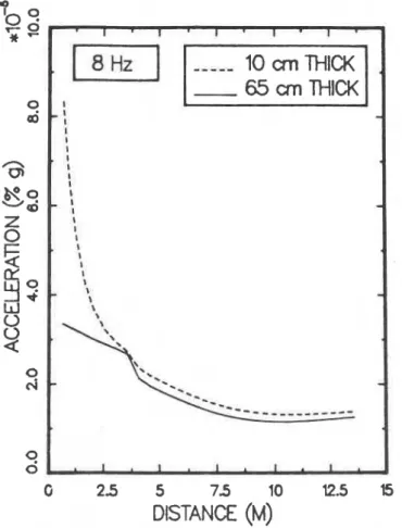
An explanation as to why improvement of the road structure is effective for reducing low frequency vibration levels at points on the roadway itself and not at points away from the road is due to the spreading of the applied load. The stiffer the road the less concentrated is the action of the load. Unfortunately, the effect of this action is local and only points close to the load experience the difference. For points away from the pavement, the loading action seems to be practically unchanged, i.e. the load remains as if concentrated. This can be clearly seen in Figure 15 where a comparison is shown between the wave fields at the surface for the 10 and 65 cm concrete pavements at an 8 Hz excitation frequency. Across the width of the pavement (0 to 3.0 m) the amplitude of the wave field for the case of the 65 cm pavement is much less than that of the 10 cm Tests On the effectiveness of vibrations screning a
pvement, whereas oulside the pavement width the two concrete wall were performed in connection with the
existing design of the road section shown in Figure 4. wave fields are almost identical.
Using a 5 metre deep concrete wall
On the other hand, the fact that improving the road structure is effective in reducing vibration levels at high frequencies may be explained as follows. As the wavelength becomes From the frequency response functions presented in Figure
shorter it approaches the road dimensions, leading to 10 it seems that the reduction of vibration amplitudes varies
propagation action within the pavement itself. Due to the from point to point in the screened
area.
While vibrationimpedance mismatch between the, road mateids and the
at "05 are reduced by the
surrounding soil a great proportion of the wave energy is presence of the concrete wall, there is only a slight
trapped within the pavement (box effect). For long reduction at the 12.05 m location.
wavelengths, however, the pavement behaves more like a rigid body, i.e. there is no action, and therefore
Using
a 10
metre deep concrete wall
most of the wave energy is transmitted to the soil. As the As would be expected, a significant reduction of vibration base of the road becomes thicker, lower frequency amplitudes occurs in comparison with the 5 m deep wall. components start to propagate in the subbase structure. This would explain the effectiveness of soil improvement below can be seen Figwe 'Iy there is a substantial the road since it would create a bigger box of sufficient reduction especially at frequencies close to the fundamentalimpedance mismatch with the rest of the soil. frequency of the road/subgrade system. However, the
reduction of vibration levelsat 12.05 m is lower than that at 5.05 m, as was observed with the case of the 5 m wall.
7
CONCLUSIONS
5.3
Effect of Soil Improvement
The calculations for soil improvement were carried out in conjunction with the modified road design, shown in Figure 5. FEM calculations were performed for improvement depths of 13.55 m, 8.55 m and 6.05 m, and the resulting response functions are shown in Figures 12, 13, and 14, respectively. It can be seen that substantial reduction in vibration amplitudes can be attained for almost all frequencies. The greater the depth of the improved area, the greater the reduction in amplitudes, especially for frequencies at or near the fundamental frequency of the roadlsubgrade system. For frequencies higher than about 15 Hz, the vibration reduction is almost the same for the three soil improvement depths.
Based on the FEM simulations of the site considered in this study, the following conclusions are reached:
Increasing the stiffness and mass of the road structure is not effective for reducing traffic- induced vibrations in the frequency range of interest. However, improvement of the road structure would slow road deterioration and hence indirectly forestall vibration problems by preventing cracking and structural damage, which are the major causes for vibration generation. The substantial depth necessary for concrete walls
to be effective in reducing ground vibrations renders them impractical.
Soil improvement under the road is an effective remedial measure for reducing traffic-induced
5 m 1 5 2 0 n
FREWENCY (HZ)
o 5 m s m n 3 g
FREQUolrCl (Hz) . .
Figure 9 Effect of using a 65 cm deep concrete pavement.
Q ; . ,
F]
0 m-
t z W Z u Q 0, " 0 0 - . 1 0 5 10 15 20 25 Jl FREQUENCY (HZ)Figure 10 Effect of screening ground vibrations with 5 m deep concrete wall
0 0 0 5 I0 15 20 25 30 FREQUENCY (ti:) 0 5 10 15 20 25 30 FREQUENCY (Hz)
ACKNOWLEDGEMENTS
-
65
an
THICK
X
G 2 5 5 7 5 10 12.5 b
DISTANCE (M)
Figure 15 Vertical wave fields at the surface for 10 cm and 65 an thick concrete pavements.
vibrations. In addition, since the bearing capacity of the soil is also improved, the structural integrity of the road will be further improved, and hence indirectly lead to less vibration generation. The degree of vibration reduction depends on the soil improvement design which is a highly specialized field and beyond the scope of this study. Increasing the soil modulus by at least a factor of 2 and an improvement depth of about 8 m resulted in satisfactory reduction of vibration levels for the site considered in this study.
The fundamental frequency of the roadJsubgrade system is governed by the properties and profile of the site. None of the remedial measures that were analysed succeeded in significantly altering it.
This study was conducted for the service de gdnie, Ville de Hull, Quebec, with partial funding from the Quebec Ministry of Transportation and the National Research Council of Canada. The authors are grateful Lo Messrs. R. Glazer and J. Marans for their help with field experiments and data processing, and to Dr. K.T. Law and Messrs. T.
Hoogeveen and A. Laberge who provided the soil surveys. The cooperation of the service de genie, Ville de Hull, the Transit Authority of Outaouais and the homeowners on Mont-Bleu Blvd. is gratefully acknowledged.
REFERENCES
Al-Hunaidi, M.O., and Rainer, J.H. 1990. Remedial measures for traffic-induced vibrations at a residential site. Partl: Field tests. Canadian Acoustics 19(1) 3-13 (1991).
Brorns, B.B., and Boman, P 1979. Lime columns- a new foundation method, ASCE Journal of the Geotechnical Engineering Division. Vol. 105, No. GT4, pp. 539-556. Le Houdec, D., and Picard, J. 1988. Effectiveness of screens for
reduction of vibrations in the ground, Inter-Noise 88, pp. 53 1-534.
Law, K.T. 1990. Dynamic behaviour of soils in Eastern Canada. Canadian Geotechnical Colloquium, The 43rd Canadian Geotechnical Conference, Quebec City (To be published). Lysmer, J., and Waas, G. 1972. Shear waves in plane infinite
structures, ASCE Journal of the Engineering Mechanics Division, Vol. 98, pp. 85-105.
Richart, F.E., Hall, J.R., and Woods, R.D. 1970, Vibrations of Soils and Foundations, Prentice-Hall Inc., Englewood Cliffs, N.J.
Segol, G., Lee, P.C., and Abel, J.F. 1978. Amplitude reduction of surface waves by trenches. ASCE Journal of the
Engineering Mechanics Division, Vol. 104. No. EM3, pp. 621-641.
Taniguchi, E.. and Okada, S. 1981. Reduction of ground vibrations by improving soft ground, Soils and Foundations, Vol. 21, NO. 2, pp. 99-1 13.
Tholen, Olle 1974. Markvibrationer orsakade av vagtrafic, National Swedish Road and Traffic Research Institute, Report No. 53, Stockholm, Sweden.
This paper is being distributed in reprint form by the Institute for Research in Construction. A list of building practice and research publications available from the Institute may be obtained by
writing
to Publications Section, Institute for Research in Construction, National Research Council of Canada, Ottawa, Ontario, KIAOR6.
Ce document est distribue sous
forme
de tir4B-partpar
1'Institut de recherche
en
construction. On peut obtenir une liste des publications de 1'Institut portant sur les techniques ou les redwchesen
mati& de Mtimenten
ecrivant B la Section des publications, Institut de recherche en construction, Conseil national de recherches du Canada, Ottawa (Ontario), KIA