Publisher’s version / Version de l'éditeur:
Polymer, 46, 6, pp. 1956-1966, 2005-01-19
READ THESE TERMS AND CONDITIONS CAREFULLY BEFORE USING THIS WEBSITE. https://nrc-publications.canada.ca/eng/copyright
Vous avez des questions? Nous pouvons vous aider. Pour communiquer directement avec un auteur, consultez la première page de la revue dans laquelle son article a été publié afin de trouver ses coordonnées. Si vous n’arrivez pas à les repérer, communiquez avec nous à [email protected].
Questions? Contact the NRC Publications Archive team at
[email protected]. If you wish to email the authors directly, please see the first page of the publication for their contact information.
NRC Publications Archive
Archives des publications du CNRC
This publication could be one of several versions: author’s original, accepted manuscript or the publisher’s version. / La version de cette publication peut être l’une des suivantes : la version prépublication de l’auteur, la version acceptée du manuscrit ou la version de l’éditeur.
For the publisher’s version, please access the DOI link below./ Pour consulter la version de l’éditeur, utilisez le lien DOI ci-dessous.
https://doi.org/10.1016/j.polymer.2004.10.089
Access and use of this website and the material on it are subject to the Terms and Conditions set forth at
Roll-drawing and die-drawing of toughened poly(ethylene
terephthalate). Part 1. Structure and mechanical characterization
Chapleau, N.; Mohanraj, J.; Ajji, A.; Ward, I. M.
https://publications-cnrc.canada.ca/fra/droits
L’accès à ce site Web et l’utilisation de son contenu sont assujettis aux conditions présentées dans le site LISEZ CES CONDITIONS ATTENTIVEMENT AVANT D’UTILISER CE SITE WEB.
NRC Publications Record / Notice d'Archives des publications de CNRC:
https://nrc-publications.canada.ca/eng/view/object/?id=9666a52a-5935-4728-a378-057731828257 https://publications-cnrc.canada.ca/fra/voir/objet/?id=9666a52a-5935-4728-a378-057731828257Roll-drawing and die-drawing of toughened poly(ethylene terephthalate).
Part 1. Structure and mechanical characterization
N. Chapleau
a, J. Mohanraj
b, A. Ajji
a, I.M. Ward
b,*
aIndustrial Materials Institute-NRC, Boucherville, Quebec, CanadabSchool of Physics and Astronomy, IRC in Polymer Science, Technology, University of Leeds, Woodhouse Lane, Leeds, UK Received 1 March 2004; received in revised form 23 August 2004; accepted 14 October 2004
Available online 19 January 2005
Abstract
In this work, two solid-state forming processes, namely roll-drawing and die-drawing, were evaluated for inducing high levels of orientation in toughened semicrystalline poly(ethylene terephthalate) (PET), modified with a metallocene ethylene-octene copolymer. In order to study the role of adhesion at the particle/matrix interface, the elastomer was grafted with glycidyl methacrylate (GMA). The GMA functional groups, which can graft to PET to form a copolymer, induced a reduction in the size of the elastomeric phase. The oriented toughened sheets from roll-drawing and die-drawing processes were characterized in terms of processing conditions (process and draw ratio), interfacial modification (GMA grafting), morphology (particle size and shape) and tensile mechanical properties (modulus, yield stress and toughness).
q2004 Elsevier Ltd. All rights reserved.
Keywords:Toughened PET; Morphology; Mechanical properties
1. Introduction
Orientation of polymers has been used for a long time as means for enhancing the properties of the polymers and found many applications in the areas of fibres, films, pipes and bottles. Most of the processes used for those applications orient the polymers in the melt state, where the level of property enhancement achieved is quite low. This is due to the mobility of the molecular chains attributed to the high temperature of the melt and the shaping device. To overcome the challenge of producing products with enhanced properties, numerous innovative processes such as solid-state extrusion, hydrostatic extrusion, roll-drawing, rolling with side constraints and die-drawing have been developed, in which the polymers are processed below their melting regime or above the glass transition temperature. These processes are starting to find applications in many areas such as rods, sheets and pipes and more recently thicker and more complex shapes have been produced.
Molecular orientation, as a result of the solid-state deformation, causes a high level of property enhancement in the oriented products when compared to the isotropic state. Large enhancement in modulus and toughness has been reported for several polymers that were oriented in the solid-state [1–4]. These materials have the advantages of possessing mechanical properties comparable to those of fibre-reinforced composites together with enhanced recycl-ability. Although in the draw direction there is a major increase in modulus and toughness, in general, the toughness other than in the principal draw direction reduces with draw ratio. This was confirmed in an earlier work on oriented polypropylene [5]. The oriented products, when tested transverse to the draw direction, fractured in a brittle manner, i.e. there was minimal or no plastic flow during the fracture process. The improvement in toughness together with improved mechanical properties are usually of some importance from a practical point of view.
The toughness of a brittle polymer can be improved in three possible ways, (a) reinforcing with short fibres[6], (b) plasticization [7], (c) blending small amounts of rubber particles in the brittle matrix[8] or (d) combination of the
www.elsevier.com/locate/polymer
0032-3861/$ - see front matter q 2004 Elsevier Ltd. All rights reserved. doi:10.1016/j.polymer.2004.10.089
* Corresponding author. Tel.: C44 113 3433808; fax: C44 113 3433809.
above. Orientation of a fibre-reinforced or plasticized polymer would still develop undesirable anisotropy in the oriented product. Hence in the present study, the focus has been on the third route—dispersing an elastomeric phase in a brittle polymer matrix. An accepted view on the role of the elastomer particles is that these inclusions alter the stress state in the material and induce extensive plastic defor-mation in the matrix, by the way of multiple crazing and/or shear yielding of the matrix with rubber particles stretching or tearing and debonding [9–12]. This route of producing tough oriented products was reported by Mohanraj et al.[5]. They reported a very large improvement in the impact toughness for oriented polypropylene that was blended with 25% of a polyethylene-based elastomer when tested perpendicular to the principal draw direction. Along the draw direction, the drawn blends showed a considerable improvement in toughness compared to the isotropic state.
In this work, the focus will be on the semi-crystalline PET and its impact modified versions. PET is one of the thermoplastic polymers whose morphology can be either amorphous or semi-crystalline depending on the processing conditions. The deformation behaviour of amorphous and semi-crystalline PET is very distinct. Orientation of amorphous PET involves simultaneous chain alignment; viscous flow, chain relaxation and strain induced crystal-lization [13], whereas the deformation of semi-crystalline PET involves destruction and restacking of the lamellae into the newly formed micro-fibrils[14]. Amorphous PET films and fibres have been oriented both above and below the glass transition temperature (Tg) in a variety of ways to
achieve an improvement in the mechanical properties such as modulus and strength. A Young’s modulus of up to 40 GPa has been reported to be achieved in some cases
[15–17]. While the solid-state orientation has been exten-sively reported on amorphous PET, there have been very few studies reporting the orientation of semi-crystalline PET owing to its limited commercial interest due to its inherent brittleness and opacity. Newman attempted to cold draw isotropic PET by tensile drawing but with no success
[18]. At temperatures below the Tg, the molecular chains are
‘frozen-in’ and thus, any stress applied to draw the polymer will be near the fracture stress of the material, which will result in premature fracture of the material by crazing and voiding [18–21]. Allison and Ward [22] also observed fracture when PET with crystallinity greater than 50% was cold drawn. However, at lower degrees of crystallinity, they noticed that the natural draw ratio increased with linity. The first attempt to successfully draw highly crystal-line PET was by Pereira and Porter[23]. They co-extruded pre-crystallized PET in the solid state at temperatures between the glass transition and the melting temperature. Another systematic study on the orientation of semi-crystalline PET was by Jabarin[24]. In this work, we report two solid-state orientation processes that have been successfully used in the past to produce highly oriented
polymer products that have both commercial and techno-logical interests.
Many studies have addressed the effect of functionalized elastomers on the toughening of PET, most of them focusing on styrene-butadiene-styrene copolymers [25–28]. Recently, polyolefins produced with metallocene catalysts have been used successfully as impact modifiers [29,30]. Interfacial modification is achieved using elastomers containing functional groups that can graft to PET to form a copolymer. In the present work, glycidyl methacrylate (GMA) was grafted onto the elastomer phase to act as an interfacial agent between the PET and the elastomer. GMA has become popular over the other graft monomers[25,31, 32] like di-butyl maleate and maleic acid because of the presence of both acrylic and epoxy groups. The acrylic functionality facilitates co-polymerization with vinyl mono-mers and the epoxy functionality enables chemical bonding with the carboxylic acid and the hydroxyl containing polymers.
The acrylic group chemically bonds to the elastomer phase and the epoxy group bonds to the parent polymer. Papke et al.[33]and Loyens et al.[34]confirmed this in a recent study. They noted that all the epoxy functions remained un-reacted after the GMA was grafted to the ethylene/propylene/diene rubber. During the in situ blend-ing process, the carboxyl end group or the hydroxyl end group of the PET bonds with the epoxy functional group of the grafted elastomer by epoxy ring opening reactions.
The addition of GMA grafted polyolefins has also been shown useful for the reactive compatibilization of blends of polyolefins with PET. In such blends, a polyolefin-polyester graft copolymer is generated in situ by a reaction involving the grafted epoxy moieties and the carboxyl/hydroxyl polyester end-groups[30].
Although much effort has been done on investigating the key parameters affecting the mechanical behaviour of rubber-modified thermoplastics (molecular weight of the components, morphology, testing conditions, cavitation, crazing and shear yielding), the structure-properties relationships of the oriented toughened polymers still needs to be addressed. It is thus the objective of this work to investigate the effect of impact modification of PET on its drawability, structure development and mechanical per-formance. This work is a collaborative effort between the School of Physics and Astronomy, Leeds (UK) and IMI (Canada) to understand the fracture behaviour of oriented polypropylene and polyethylene terephthalate obtained from the roll-drawing and die-drawing processes and effectively improve the transverse toughness of the oriented products.
In this first paper, we report the production, structure, morphology and the mechanical properties of oriented PET homopolymer and oriented impact modified PET blends obtained from the roll-drawing and die-drawing processes. A second paper will focus on studying the fracture behaviour of isotropic and oriented toughened PET using
the J-integral approach. The oriented sheets will be tested both parallel and perpendicular to the draw direction and the fracture behaviour will be compared to that of the isotropic PET homopolymer and blends.
2. Experimental
2.1. Materials
The materials used in this study were all commercial grades in the form of pellets. The impact modifier was Engage 8150 (mPE), manufactured by Dow DuPont. This elastomer is a metallocene ethylene-octene copolymer containing 25% octene. The PET was Cleartuf 8006 from Shell. The PET-based blends were prepared in a co-rotating twin-screw extruder at 290 8C and 200 rpm. Blends contain-ing 10% by weight mPE were prepared and pelletized. In order to investigate the effect of interfacial adhesion, the mPE was grafted in-house by melt free radical grafting of glycidyl methacrylate (GMA).
Rectangular flat profiles of cross-section 5 mm thickness and 100 mm width were melt extruded and then stored for later use in the roll-drawing and die-drawing processes. In this study, three materials were characterized in terms of their processing, structure and property relationships. They are X—PET homopolymer, Y—a blend containing 10% by weight of non-grafted elastomer and Z—a blend containing 10% by weight of grafted elastomer.
2.2. Roll-drawing process
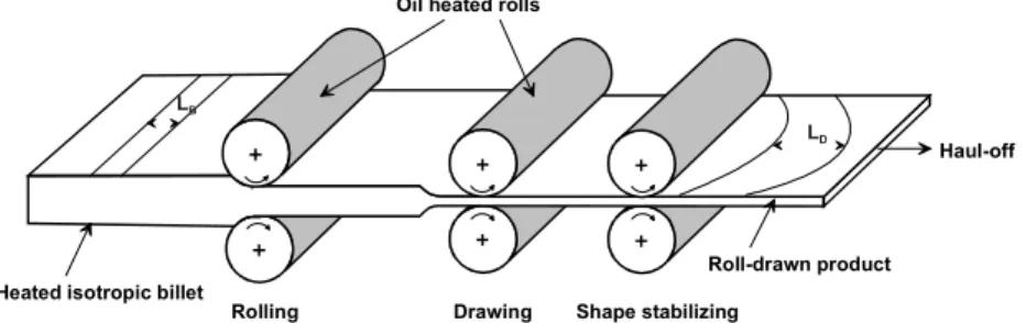
The roll-drawing setup consisted of a series of 6 pairs of
rolls as shown inFig. 1. The majority of the reduction takes place between two pairs of rolls, the first pairs of rolls (working rolls) rotating at a slower feed speed than the second set (traction rolls). These two pairs of rolls are heated and enclosed in a temperature controlled chamber. The drawn sheet leaving the second set of rolls is subsequently cooled by the successive rolls. The traction force exerted by the traction rolls produces pronounced anisotropy in the roll direction and little change in the transverse properties from those of the isotropic material
[35,36]. When no traction pull is exerted on the material, the process resembles the conventional rolling process that produces biaxial orientation in the sheet[37,38].
Data on profile speed, roll speed, tension at the last station, draw ratio and temperatures were monitored during the roll-drawing process. In this study, PET and the blends were drawn at 170 8C and at a constant speed of 200 mm/min. The extent of deformation in the length direction was determined by measuring the distance between two ink marks before and after the process.
2.3. Die-drawing process
In die-drawing, a heated polymer billet is drawn through a heated die of reducing cross-section. A schematic sketch of the die-drawing process is shown in Fig. 2. In addition to deforming in the die, the material undergoes free drawing on exiting the die with the heat being lost continuously to the surroundings. At some point after the die-exit the product approaches a stable state with no further plastic deformation. On each extruded sheet, an oriented tag of approximately 1 mm was made by rolling to aid the start up procedure for the die-drawing process. The sheets were placed in a heated
Fig. 1. Schematic of the roll-drawing process.
chamber maintained at 170 8C and the tag gripped by the haul-off unit. After attaining thermal equilibrium, the drawing was started initially at 50 mm/min to draw the initial tag and once the oriented tag emerged out of the die, the draw speed was
increased to 200 mm/min. The drawing load was monitored throughout the run. The die exit was varied to yield several nominal reduction ratios, which is defined as the ratio of thickness of the billet to the thickness at the die-exit. As in the
Fig. 3. Crystallinity as a function of draw ratio for pure and modified PET, for both orientation processes.
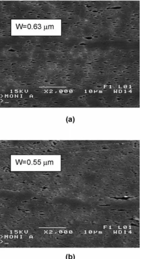
Fig. 4. SEM micrographs of isotropic PET-based blends. Left column: 10 wt% mPE (Y). Right column: 10 wt% GMA-mPE (Z). (a) transverse direction. (b) Longitudinal direction.
roll-drawing process, the deformation in the axial direction was determined by measuring the distance between two ink marks before and after the process.
In both the roll-drawing and die-drawing of sheets, as a result of the tension exerted by the haul-off, there is a reduction along the width and thickness direction and elongation in the axial direction. Hence three deformation ratios can be defined for these processes. They are:
† reduction ratioZratio of the thickness before and after drawing
† width ratioZratio of the widths before and after drawing † axial draw ratioZratio of the lengths after and before
drawing.
In this part and in the subsequent paper, the axial draw ratio will be quoted as the ‘actual draw ratio (RA)’, since this
will have a dominant effect on the properties of the drawn sheet. Because the material draws outside the working rolls in the case of the roll-drawing process and outside the die in the die-drawing process, the final reduction ratio is always greater than the nominal reduction ratio (ratio of the billet thickness to the work-roll gap).
2.4. Material characterization
The crystallinity of samples obtained at different draw
ratios in both processes was determined from DSC measurements. The enthalpy of melting of completely crystalline PET was taken as 140 J/g.
The morphology of the blends was investigated by scanning electron microscopy (SEM). Specimens were cut from the roll-drawn and die-drawn sheets, in the longitudi-nal and transverse directions. Microtoming was performed at room temperature after annealing at 80 8C for 12 h, and immersion in boiling toluene for 4 hours. A thin gold/-palladium coating was applied prior to the observations in the microscope.
Image analysis was performed to determine the size and shape of the dispersed phase from the images of the cross-sections. The extent of deformation was quantified using a shape factor, f, defined as:
f Z P
2
4pA (1)
where P and A are the perimeter and the surface area of the particle, respectively. A value of unity for f represents a sphere. This value is higher for elongated particles.
The tensile mechanical properties at room temperature in the longitudinal directions were measured in an Instron tensile tester according to standard ASTM D638 on type IV specimens. Specimens were machined using a cutting saw. The test speed was 50 mm/min and the elastic modulus was determined using an extensometer. The reported values represent the average of 5 tests.
Infrared dichroism measurements were made on a Nicolet 170SX FT-IR spectrometer at a resolution of 4 cmK1 in the reflection mode using a low-angle (118) specular reflection accessory from Spectra-Tech Inc. Each spectrum was the result of an accumulation of 128 scans. A front-surface gold mirror was used as reference. Drawn samples were mounted with the draw direction perpendicu-lar to the plane of incidence. The beam was poperpendicu-larized by means of a wire-grid polarizer (ZnSe substrate) from Spectra-Tech. Spectra were measured at two orthogonal polarizations (parallel and perpendicular to the draw direction) without changing the sample position. The Kramers-Kronig transformation was performed with the commercial software Spectra Calce from Galactic Indus-tries Corporation, using their Maclaurin’s series algorithm to perform the integration. If q is the orientation of the chain
Fig. 5. Morphology of roll-drawn 10 wt% GMA-mPE (Z) for two draw ratios (RA). (a) RAZ2.3. (b) RAZ4.5. Micrographs taken in the transverse direction. The average width of the particles, W, is given.
Table 1
Shape factor, f, obtained from morphological analysis
Material Draw ratio Roll-drawn Die-drawn
Y 2.3 2.8 4.4
3.2 6.8 4.8
Z 2.3 2.3 3.0
3.2 4.2 5.0
Max. RA 5.5 5.7
Values are given for particles observed in the draw (longitudinal) direction. Maximum draw ratio (max. RA) is 4.5 and 3.8 for roll-drawing and die-drawing, respectively.
axes with respect to the draw direction, the orientation average hP2(cosq)i for the chains is given by,
hP2ðcos qÞi Z
D K1
D C2 2
3 cos2a K1 (2)
Where D is the dichroic ratio (ratio of the parallel to the perpendicular absorbencies) of a vibration corresponding to a transition moment making an angle a with the chain axis.
3. Results and discussion
The maximum drawability of PET and the blends during drawing was determined. Slightly higher maximum draw ratios were obtained when performing roll-drawing. X (PET) was drawn up to a maximum draw ratio of 5.4. Adding 10 wt% of the modifier produced a slight reduction of the drawability. A maximum draw ratio of 4.5 was obtained for both Y (10 wt% mPE) and Z (10 wt%
GMA-mPE). The samples X, Y and Z were all die-drawn under the same operating conditions up to a draw ratio of about 3.8. These results indicate that adding the mPE modifier does not much affect the drawing behavior of PET. Also, grafting the mPE dispersed phase with glycidyl methacrylate (GMA) does not influence significantly the drawability.
The melting behavior of pure PET and PET-based blends were investigated by DSC.Fig. 3shows the crystallinity of PET and the blend containing 10 wt% GMA-mPE as a function of draw ratio for both the roll-drawing and die-drawing processes. Similar results were obtained for the non-grafted blend. In all cases, a small increase of the crystallinity with draw ratio was observed. Crystallinity is higher in the case of the die-drawn materials, probably due to the annealing step prior to drawing. This higher crystallinity could be responsible for the slightly lower drawability reported above. The addition of the mPE modifier, grafted or not, results in a decrease of the crystallinity for both processes.
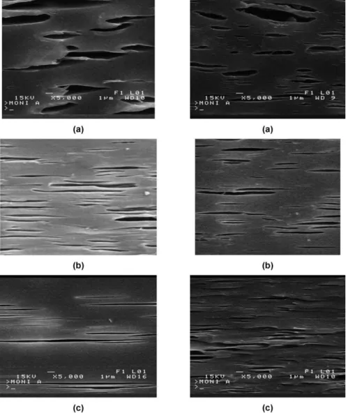
Fig. 6. Morphology of roll-drawn blends at several draw ratios (RA). Left column: 10 wt% mPE/PET blends (Y). Right column: 10 wt% GMA-mPE/PET blends (Z). (a) RAZ2.3. (b) RAZ3.2. (c) RAZ4.5. Micrographs taken in the longitudinal direction.
The morphology of the matrices and their blends was investigated by scanning electron microscopy, after etching out the dispersed phase. Care was taken to observe the centre of the specimens, both in the longitudinal and transverse directions. Pure PET did not exhibit any morphological features. For the blends, in both the isotropic and oriented state, a smaller dispersed phase size was observed for blends containing GMA-grafted mPE. This is
indicative of the efficiency of GMA grafting. This graft copolymer is expected to locate at the blend interface, decreasing the interfacial tension in the molten state and increasing adhesion in the solid-state. Similar observations on the efficiency of GMA for compatibilizing this type of system were made previously by Champagne et al. [30].
Fig. 4 shows the isotropic blends containing 10 wt% mPE without (Fig. 4(a) and (b), left column) and with GMA
Fig. 7. Morphology of die-drawn blends at several draw ratios (RA). Left column: 10 wt% mPE/PET blends (Y). Right column: 10 wt% GMA-mPE/PET blends (Z). (a) RAZ2.4. (b) RAZ3.2. (c) RAZ3.8. Micrographs taken in the longitudinal direction.
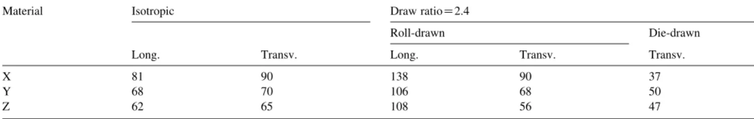
Table 2
Longitudinal and transverse yield stress at a draw ratio of 2.4
Material Isotropic Draw ratioZ2.4
Roll-drawn Die-drawn
Long. Transv. Long. Transv. Transv.
X 81 90 138 90 37
Y 68 70 106 68 50
Z 62 65 108 56 47
(Fig. 4(a) and (b), right column). The dispersed phase size (equivalent diameter) determined by image analysis was 0.97 and 0.50 mm for Y and Z, respectively. The droplets were nearly spherical, as indicated by the value of the shape factor close to 1, except in the compatibilized case, where the particles are slightly oriented in the longitudinal direction. The morphological analysis also revealed that planar orientation was successfully achieved during roll-drawing and die-roll-drawing. An example is given in Fig. 5, which shows the cross-section (transverse direction) of the compatibilized blend (Z) at two draw ratios. The shape of the particles is ellipsoidal and remains in this fashion as the draw ratio is increased from 2.3 to 4.5. The width of these ellipses is very similar to the initial diameter of the isotropic
particles and stays constant with increasing draw ratio, which is expected for planar deformation (no lateral deformation). Typical examples of the evolution of the morphology in the longitudinal direction as a function of draw ratio are shown inFigs. 6 and 7. Micrographs of the roll-drawn Z blend are presented in Fig. 6 and the shape factors, f, as determined by image analysis, are reported in
Table 1. The shape factor increases significantly with draw ratio, especially in the non-compatibilized case. Values for the maximum draw ratio of 4.5 are not given, the particles being so highly elongated that image analysis was difficult. The increase of f for the compatibilized blend is less important. However, it must be stated that the particles in this case are much smaller, and therefore more difficult to
deform, than in the previous case (no GMA). This may be another indication of the efficiency of GMA at the interface, good interfacial adhesion favouring deformation. The same analysis was conducted on the die-drawn specimens. Examples are given in Fig. 7, for Y and Z processed at draw ratios of 2.4, 3.2 and 3.8. As the draw ratio is increased, the particles become more elongated in the draw direction. The shape factor increases from 3.0 to 5.7 as the draw ratio increases from 2.4 to 3.8. Again, the value of f for the uncompatibilized blend stretched at the maximum draw ratio could not be determined.
The morphological analysis enabled to evaluate the extent of deformation and orientation of the particles during
drawing. FTIR studies were conducted to investigate the crystalline orientation of the PET matrix and the mPE modifier. The effect of the addition of the modifier on the orientation of the crystalline phase is reported inFig. 8. Data for specimens produced with the roll-drawing process are shown. Similar results were obtained for the die-drawing case. For PET, the vibration used to follow the orientation was the trans band at 1340 cmK1, which has a parallel dichroism. The orientation functions were calculated from Eq. 2 using aZ08 and are presented inFig. 8a. For PE, the 2918 cmK1 band was used; it corresponds to the CH2
asymmetric stretching whose transition moment is nearly perpendicular to chain axis (aZ708). For roll-drawn pure
Fig. 9. Tensile elastic modulus of roll-drawn PET and blends measured in the longitudinal (drawing) direction.
PET, the orientation function is observed to increase steadily with draw ratio and levels off around a draw ratio of about 4, which has been generally observed for other semi-crystalline polymers. For modified blends, this orien-tation is lower since a portion of the deformation was used to deform the PE phase. This portion of deformation is more important when a good adhesion is present between PET and PE, implying an even lower orientation for PET, but a higher orientation for the PE phase, as can be observed on
Fig. 8(b).
The tensile properties were determined as a function of draw ratio. The elastic modulus, yield stress, elongation at break and toughness (area under stress–strain curve) for PET and the blends were evaluated in the longitudinal (drawing) direction. Similar observations were made for both roll-drawn and die-drawn materials and the results are shown inFig. 9for the roll-drawing process only. In general, the elastic modulus increased with draw ratio. FTIR results showed that the crystalline orientation increased with draw ratio and reached a maximum at a draw ratio around 4. The modulus continues to rise after draw ratio 4, and in fact shows a monotonic increase with draw ratio, suggesting that the overall orientation is increasing steadily. Adding 10 wt% of modifier resulted in a decrease of the elastic modulus (Fig. 9) of PET at low draw ratios, which is expected when adding a rubbery modifier. At the highest draw ratios (above 4), the properties of the blends (Y and Z) are close or equal to those of pure PET. Although the properties of the blends are sometimes lower than those of pure PET, it must be mentioned that the absolute values remain very high.
In Fig. 10, the yield stress of roll-drawn PET and the blends in the longitudinal direction are compared as a function of draw ratio. The yield stress in the longitudinal
direction of the oriented PET and blends increases steadily with draw ratio suggesting reduced ductility at higher draw ratios. Table 2 shows a comparison of the yield stress measured for the isotropic PET and the blends, as well as values for specimens oriented at a draw ratio of 2.4, both using roll-drawing and die-drawing. It can be seen that the initial melt extruded materials are not quite isotropic, but show yield stresses which are somewhat greater in the transverse direction than in the longitudinal direction. After either roll-drawing or die-drawing the longitudinal yield stress increases and the transverse yield stress either remains at the same value or decreases.
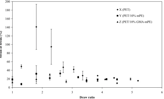
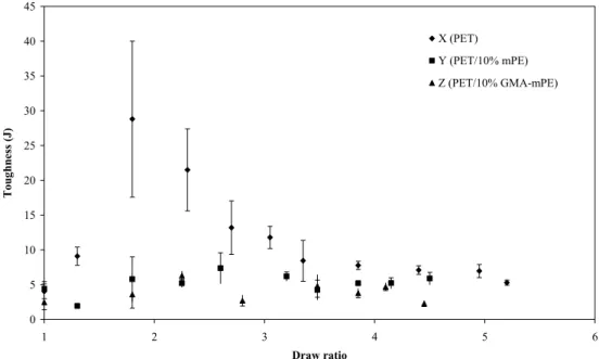
The elongation at break and toughness (Fig. 11 and 12) of pure PET are dramatically increased up to a draw ratio of about 2. These properties decrease towards those of the isotropic sample at draw ratios between 2 and 3. This spectacular increase of the ultimate properties was not observed for the blends, with or without grafting. Both elongation at break and toughness of Y and Z remained essentially constant at all draw ratios.
4. Conclusions
The structure and mechanical performance of modified poly(ethylene terephthalate) (PET) processed using roll-drawing and die-roll-drawing were investigated. A metallocene polyolefin (mPE) elastomer was used as the modifier. The mPE was grafted with GMA to achieve compatibilization. Morphological analysis confirmed the efficiency of GMA grafting; a decrease of the dispersed phase size was observed. The drawability of pure PET and blends contain-ing 10 wt% mPE, with and without interfacial modification, was investigated. Higher maximum draw ratios were
obtained by roll-drawing. The addition of the modifier lowered slightly the drawability of neat PET and the crystallinity. The molecular orientation of pure PET and the mPE modifier was evaluated using FTIR. The orientation for pure PET increased up to a draw ratio of 4. Adding the modifier reduced the orientation of PET; this reduction in orientation being even more significant when the mPE was grafted with GMA. The elastic modulus and yield stress of PET and the blends increased with draw ratio, the properties of the blends (grafted or not) being slightly lower or equal to those of PET. The ultimate tensile properties (elongation at break and toughness) of neat PET increased and exhibited a maximum at a draw ratio of about 2. Adding the mPE modifier did not result in an improvement of the ultimate properties.
References
[1] Ward IM. Adv Polym Sci 1985;70:1–70.
[2] Zachariades AE, Porter RS, editors. High modulus polymers. New York: Marcel Dekker; 1988.
[3] Ajji A, Dufour J, Legros N, Dumoulin MM. J Reinf Plast Compos 1996;15:652–62.
[4] Morath CC, Taraiya AK, Richardson A, Craggs G, Ward IM. Plast, Rubber Compos Process Appl 1993;19:55–62.
[5] Mohanraj J, Chapleau N, Ajji A, Duckett RA, Ward IM. Polym Eng Sci 2003;43:1317–36.
[6] Paul DR, Bucknall CB, editors. Polym Blends, vol. 2. New York: Wiley; 2000.
[7] Hertzberg RW. Deformation and fracture mechanics. New York: Wiley; 1976.
[8] Bucknall CB. Toughened plastics. London: Applied Science Publi-cations; 1977.
[9] Bucknall CB, Clayton D, Keast WE. J Mater Sci 1972;7:1443–53.
[10] Bucknall CB, Clayton D, Keast WE. J Mater Sci 1973;8:514–24. [11] Wu J, Mai YW. Mater Forum 1995;19:181–99.
[12] Van der Wal A, Gaymans RJ. Polymer 1999;40:6067–75. [13] Peterlin A. Polym Eng Sci 1976;16:126–37.
[14] Peterlin A. Coll Polym Sci 1987;265:357–82.
[15] Huang B, Ito M, Kanamoto T. Polymer 1994;35:1329–31. [16] Itoyama K. J Polym Sci, Part C: Polym Lett 1987;25:331–8. [17] Kunugi T, Suzuki A. J Appl Polym Sci 1996;62:713–9. [18] Newman S. J Polym Sci 1958;27:563–6.
[19] Foot JS, Ward IM. J Mater Sci 1972;7:367–87. [20] Stearne JM, Ward IM. J Mater Sci 1969;4:1088–96. [21] Pecorini TJ, Hertzberg RW. Polymer 1993;34:5053–62. [22] Allison SW, Ward IM. Br J Appl Phys 1967;18:1151–64.
[23] Pereira JRC, Porter RS. J Polym Sci, Part B: Polym Phys 1983;21: 1147–61.
[24] Jabarin SA. Polym Eng Sci 1991;31:1071–8.
[25] Hale W, Keskkula H, Paul DR. Polymer 1999;40:3353–65. [26] Tanrattanakul V, Hiltner A, Baer E, Perkins WG, Massey FL, Moet A.
Polymer 1997;38:2191–200.
[27] Tanrattanakul V, Perkins WG, Massey FL, Moet A, Hiltner A, Baer E. J Mater Sci 1997;32:4749–58.
[28] Tanrattanakul V, Hiltner A, Baer E, Perkins WG, Massey FL, Moet A. Polymer 1997;38:4117–25.
[29] Chapleau N, Huneault MA. J Appl Polym Sci 2003;90:2919–32. [30] Champagne MF, Huneault MA, Roux C, Peyrel W. Polym Eng Sci
1999;39:976–84.
[31] Kalfoglou NK, Skafidas DS, Kallitsis JK, Lambert JC, Van der Stappen L. Polymer 1995;4453–62.
[32] Pietrasanta Y, Robin JJ, Torres N, Boutevin B. Macromol Chem Phys 1999;200:142–9.
[33] Papke N, Karger-Kocsis J. J Appl Polym Sci 1999;74:2616–64. [34] Loyens W, Groeninckx G. Macromol Chem Phys 2002;203:1702–14. [35] Ajji A, Dumoulin MM, Cole KC. Eng Plast 1996;9:216–24. [36] Ajji A, Cole KC, Dumoulin MM, Ward IM. Polym Eng Sci 1997;37:
1801–8.
[37] Gezovich DM, Geil PH. J Mater Sci 1971;6:509–30.
[38] Chaffey CE, Taraiya AK, Ward IM. Polym Eng Sci 1997;37: 1774–84.