Publisher’s version / Version de l'éditeur:
Vous avez des questions? Nous pouvons vous aider. Pour communiquer directement avec un auteur, consultez la première page de la revue dans laquelle son article a été publié afin de trouver ses coordonnées. Si vous n’arrivez pas à les repérer, communiquez avec nous à [email protected].
Questions? Contact the NRC Publications Archive team at
[email protected]. If you wish to email the authors directly, please see the first page of the publication for their contact information.
https://publications-cnrc.canada.ca/fra/droits
L’accès à ce site Web et l’utilisation de son contenu sont assujettis aux conditions présentées dans le site LISEZ CES CONDITIONS ATTENTIVEMENT AVANT D’UTILISER CE SITE WEB.
Laboratory Memorandum; no. LM-2004-09, 2004
READ THESE TERMS AND CONDITIONS CAREFULLY BEFORE USING THIS WEBSITE. https://nrc-publications.canada.ca/eng/copyright
NRC Publications Archive Record / Notice des Archives des publications du CNRC :
https://nrc-publications.canada.ca/eng/view/object/?id=b54f3329-5c5d-4f47-8593-3acb2685ebb6 https://publications-cnrc.canada.ca/fra/voir/objet/?id=b54f3329-5c5d-4f47-8593-3acb2685ebb6
Archives des publications du CNRC
For the publisher’s version, please access the DOI link below./ Pour consulter la version de l’éditeur, utilisez le lien DOI ci-dessous.
https://doi.org/10.4224/8895149
Access and use of this website and the material on it are subject to the Terms and Conditions set forth at Design of a Yaw Restraining Heave Post
Ocean Technology technologies oc ´eaniques
Laboratory Memorandum
LM-2004-09
Design of a Yaw Restraining Heave Post
R. Shandera
April 2004
Summary
The Institute for Ocean Technology is a national research facility that specializes in the testing of scale models. In many cases they are models of ships and structures that may one day see production. The information gathered from the testing facilities will give the people who designed the vessel a sense of how the vessel will perform in the real world. Often the models are not self propelled, yet propulsion must come from the carriages above the tow tanks. Often the
propulsion is transferred to the models through the use of a heave post. The current heave post does not have the ability to restrict the motion of the model in yaw. Therefore, the grasshopper is used to accomplish this task. There are a number of problems associated with this device that are considered undesirable. To eliminate the use of this piece of equipment a new heave post was designed. In order to have a heave post which functioned properly a set of design criteria were established. The design criteria lead to the development of several designs from which the best suited candidate was chosen. The new heave post, will supplement the existing heave post giving the facility the ability to operate more smoothly since testing will occur in both tanks simultaneously.
Table of Contents
SUMMARY ... I TABLE OF FIGURES ... II 1.0 INTRODUCTION... 1 2.0 EXISTING DESIGN ... 2 3.0 DESIGN CRITERIA ... 6 4.0 DESIGN ... 74.1 ALTERNATIVE HEAVE POST DESIGNS... 8
4.2 CHOSEN DESIGN... 9
4.3 FRAME DESIGN... 10
5.0 FUTURE CONSIDERATIONS ... 15
6.0 CONCLUSION... 15
7.0 APPENDIX – A: FABRICATION DRAWINGS 8.0 APPENDIX – B: CALCULATIONS
Table of Figures
Figure 1. The existing medium heave post... 2Figure 2. The current yaw restricting "The Grasshopper". ... 4
Figure 3. Large tow post... 7
Figure 4. The design drawing for the yaw restraining heave post is shown above. ... 9
Figure 5. An early design of tow post support system. ... 11
Figure 6. The final design of the frame... 12
1.0 Introduction
The Institute for Ocean Technology (IOT) is a part of the National Research Council (NRC). The main component of their research is model testing. The models that are tested at IOT’s facilities consist of virtually any structure that will interact with the ocean. Everything from the Hibernia platform to underwater vehicles has been tested in the facilities at IOT. A majority of the models tested at IOT are scale models of ships. These models are tested to determine their performance under various conditions. In most of these tests, models require some form of propulsion. Some models are self-propelled. However, more are propelled through the carriages situated over the various tanks. The clear water towing tank (CWTT) carriage is capable of reaching a top speed of 10m/s. The device employed to provide propulsion varies depending on the type of model being tested, many times a simple heave post is used. This post is designed to allow the model to move freely in the vertical direction (heave), and rotate freely about that axis of the post (yaw) and is used in conjunction with a gimbale that allows the model to pitch and roll. However it is not always desirable to allow the model to yaw. If a large model is unstable it is possible for it to yaw until it breaks the gimbale. The gimbale has the ability to resist yaw moments but has no
strength in that direction. Currently IOT does have the ability to keep a model from yawing. However, this will be discussed later. This was the driving force for the need of a yaw restraining heave post. This post is not a complete
existing post. This will allow both the ice tank and the fresh water tow tank to operate at the same time without equipment availability causing a problem.
2.0 Existing Design
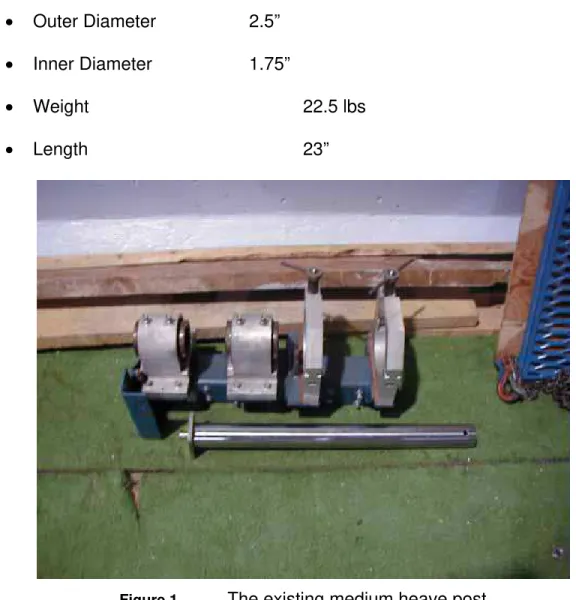
There are several tow posts at IOT. They vary in both diameter and length. Currently the medium heave post and gimbale are used more often for the purposes of experimentation. The dimensions of that post are:
• Outer Diameter 2.5”
• Inner Diameter 1.75”
• Weight 22.5 lbs
• Length 23”
Figure 1. The existing medium heave post
This post can be seen in figure 1. Also shown in this figure is the frame that supports the post. The post is allowed to move freely in both heave and yaw. It
is not allowed to move in the horizontal direction. This is obviously a necessity if the post is to transfer any force to the model. The heave post is strong enough to resist virtually any force applied via a model. The limiting factor of this design is the linear bearings that restrain the yaw of the model. The average model is accelerated at 0.4m/s2, and the operator of the carriage gradually accelerates large models to prevent the bearings from becoming overloaded. However the real danger of failure occurs when the operator must fully apply the brakes of the carriage. This results in an deceleration of 3 m/s2. Forces much greater in magnitude are generated at this acceleration. A quick inspection of Newton’s second law shows that the same model will generate a force 7 times larger occurs during a sudden stop than under normal operating conditions.
F = ma (1)
Where: F = force m = mass a = acceleration
The medium heave post does perform the job it was designed to do. However the need to restrict the motion of the model about the vertical axis presented itself.
The institute is currently able to restrict the motion of the model in yaw. This is done through application of a device known within the institute as “the
attaches to the bow of the model and the square post is used to resist the yaw. There are two major problems associated with the grasshopper. First, there is a counterweight that can be seen to the left of the figure 2. When the model has trimmed, the counterweight has no effect. However, when a model is pitching and heaving due to wave and wind interactions, the counterweight has a
detrimental effect. When wave and wind are applied to a model the intention is to measure how the model responds.
Figure 2. The current yaw restricting "The Grasshopper".
The counterweight does not allow the true motion of the model to be observed. The counterweight actually has a dampening effect on the motion of the model. This reduces the accuracy of the data collected and does not allow for a good correlation between model motion and full scale motion. The second problem associated with the grasshopper is its length. The grasshopper is not always
long enough to reach the model and hold it at the appropriate angle. When this situation occurs a number of six-inch extensions are added. This reduces the flexural and torsional stiffness of the apparatus. The grasshopper acts like a cantilever beam. As the length of the cantilever beam increases, so does the amount the end of the beam will deflect under a given load. Also, as the length increases, so does the angle of twist that will be experienced. These
phenomena are determined by the following equations:
GJ TL
=
θ (2)
Where: θ = the angle of twist T = the applied torque
L = the length of the member G = the modulus of rigidity
J = the polar moment of inertia of the cross section
EI PL 3 3 = δ (3)
Where: δ = the deflection of the end of the post P = the applied load
L = the length of the post E = the modulus of elasticity I = the moment of inertia
3.0 Design Criteria
The design of the tow post is a classic design problem. The post is required to be longer, lighter, and stronger then the current post. This does not give any specific limit to the characteristics of the design. It was determined that the post must meet the following characteristics:
• Weight: 45Lbs.
• Heave: 27in. (amount of heave for long medium diameter post.)
• Model Size:
o Length 7m
o Mass 1000 kg
• Acceleration: 3m/s2
• Post must mount to the large tow post shown in figure 3.
• The ability to resist yaw forces while being able to trim the yaw angle. • The ability to lock the post in heave must be present.
Figure 3. Large tow post.
4.0 Design
There were a number of possible designs considered for the new heave post. There are several characteristics that are common among all the designs. First, the inclusion of a linear rail and bearing system is common to all designs. The linear rail and bearing insure that the post will heave properly. That is, the coefficient of friction will be lowered greatly, which will keep the heave post heaving freely. Also, the bearings will be used to counteract any yaw force acting on the model. The bearings chosen for the new heave post are THK SHS 15LC. These rails were chosen over the THK SHS 15C bearings because they have a higher critical load of 35kN. Under an applied load of 35kN the balls in the bearing will start to cause indentations on the rails that will decrease the
effectiveness of the rail system. Also, all the designs must be mounted in some way to the front of the existing tow post shown in figure 3. This will allow the cross-sectional area of the heave post to be increased in comparison to the existing design. An increase in cross-sectional area will increase the strength of the post in virtually all-loading conditions. This is important since the length of the post is also going to increase. The fact that the heave post is to be mounted away from the center of the tow post will allow for easy adjustment of the yaw angle of the model with respect to the tank wall. It is possible to simply have a pivot post with a treaded rod at another location to adjust the yaw angle with the heave post in this location. However, if the post were aligned with the center of the tow post, a much more complicated gearing system would likely be used.
4.1 Alternative Heave Post Designs
There were a number of alternative designs considered for the heave post. They consisted of different geometries and the use of different materials. The first design considered was simply an alteration of the current heave post. A 2.5” outer diameter hallow shaft was considered. The existing design is able to withstand any force applied to the model. Again the linear bearings are the limiting factor to the force that can be applied. This design would difficult to fabricate. The post would need to be machined to allow for proper alignment of the linear rails. Even though it is possible for this to be done with the boring mill it would require more work and reduce the strength of the post. Then, a carbon fiber square post with external dimensions of 3” x 3” was tried. The use of a
carbon fiber post would have reduced the weight of the post and will not be sacrificing a great deal of strength. However, the technology is not present at IOT to manufacture such a post, purchasing a carbon fiber sail boom was considered. A closer inspection was made to the process that will be used to attach the linear rails. The process would be very complicated and greatly
increase the price of the design. If this technology were more readily available at IOT then this material would have become a more viable option.
4.2 Chosen Design
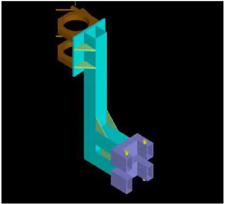
Figure 4. The design drawing for the yaw restraining heave post is shown above.
The chosen design is that of a 3” x 3” x 3/16” steel box tube with a length of 40”. The use of the box tube not only increased the moment of inertia but also
reduced the weight of the post. However, the addition of the linear rails and the mounting surfaces for those rails increased the weight to approximately 40lbs. The new design is heavier then the existing design, however for this is to be expected considering the new design is 17” longer then the current design. The weights of 40” length post are 23lb and 35lbs for the new and existing design respectively. This is before the addition of the linear rail. The maximum force that will be experienced when the post is in operation is determined by the maximum acceleration of the carriage. Under normal operating conditions an acceleration of 0.4m/s2 will be experienced. However, it is possible that an acceleration of 3m/s2 will be experienced when the carriages brakes are fully applied in an emergency. The post may be able to withstand large forces, but without a support system it is not able to propel a model.
4.3 Frame Design
The support system for the tow post underwent the most drastic changes from the beginning of the design process. The design of the frame of the post was an evolutionary process. When a new feature was identified the design of the
support system changed. The major functions that the frame required to possess are:
• Allow the post to heave freely. • Resist yaw forces.
• Allow for the attachment of the existing wake flow survey equipment. • Have the ability adjust the model’s yaw angle
Figure 5. An early design of tow post support system.
The design for the frame started very simply. An early design for the post frame can be seen in figure 5. This design was very simple and very light. It is simply a number of pieces of 4” x 4” box tube welded together. This design was very strong, but there are a number of problems associated with the design. First, there is no way to preload the linear bearings. This is a technical problem that will affect the effectiveness of the device. During assembly the bearings position must be adjusted and pre-loaded until the post heaves freely. This is, of course, a major problem that has been eliminated in future iterations of the heave post frame. Another problem associated with this design is the spacing between the bearings. It is common practice to provide at least one bearing length between the bearings. This helps to reduce the amount of force acting on each bearing.
The frame is much too long, and will behave like a cantilever beam. Like all cantilever beams as the length increases the end of the post will deflect much more. Also this frame does not allow the yaw angle to be trimmed. This is a necessity to eliminate any error introduced during the installation of the frame.
Figure 6. The final design of the frame.
The final design of the heave post frame is shown in figure 6. This design has incorporated all function that was necessary. This increased the number of components needed to full fill the design criteria. As the number of components increased so did the weight. However, for the components possessing the largest volume, the large tow post clamps are to be made of aluminum to reduce their weight. The weight is not a major problem as far as testing is concerned. The tow post will support the weight of the frame. The only weight that is of major concern is that of the heave post. The design of the frame is very
compact. It is not possible to see the scale of this design from figure 6. However, the frame is approximately 23” high and 12” wide. In fact, it will be possible to restrict the motion of heave post and crane the heave post into position while it is attached to the large tow post. This makes the job of the people setting up the models in the testing facilities easier. They will no longer need to move the post into position with a boat and have the risk of falling into the tow tank. There are a number of features that this frame possesses that the first design does not. It is now possible to adjust the yaw angle of the model. This will insure that the model will run straight down the tank. However, the amount of adjustment present is only one or two degrees in either direction. This all that is required to trim any error introduced due to the installation. Another option that needed to be designed is a system to restrain the post in heave. In the case of a wake flow survey the model is set at a certain level in the water and a certain pitch angle is also imposed. The axial loading on the post during
claming must not be applied to the bearings. If either the weight of the model or the buoyant force is too great, then the bearings may fail. Therefore, it was decided to attach the heave restraint to the frame and clamp to the linear rails. The final frame design was also required to have one final feature that needed to be added. This was the ability to impose an angle on the model and it is also a necessity. There is equipment existing already for this purpose. After a number of potential designs it was determined that attaching the existing equipment would be simpler and more cost effective. This required a slight modification to the large clamps to accommodate two bolt holes. This will allow both tanks to
conduct testing at the same time without equipment being an issue. The new design of both the heave post and its corresponding frame are more complicated then the existing heave post. However, more options are available and the major problem associated with the grasshopper has been eliminated. Even though a number of improvements have been made over the existing post, the new post may need some improvements in the future. The final design can be seen in figure 7.
Figure 7. Final assembled design.
5.0 Future Considerations
There are a number of areas in which the heave post and its frame can be improved. As the frame is currently designed it is impossible to measure the amount of yaw force present in the model. This is due to the positioning of the pivot post in relation to the tow post. The pivot post is not in alignment with the tow post. This means that the treaded rod will carry a certain amount of the tow force. Since a portion of the tow force will always be present there will never be a time when there is no force acting on the bolt. This makes the ability to tune the yaw almost impossible. In the future this process can be automated. One possibility could be to use a ball screw that is able to pivot, and a stepper motor. A motor controller will adjust the angle of the post slightly by spinning in a given direction. Then a micro controller will compare the force experienced by the load cell to a previous measurement. If the force is lower then the screw will advance another step. However, if the measured force is greater then the previous it will reverse direction. This will continue to happen until the model is oriented in the proper position.
6.0 Conclusion
The design of the new heave post has been a success up to this point. The design passed the final design review and was approved for fabrication. The fabrication drawings can be seen in appendix A. The design exceeded the existing design in all areas. The only factor that is keeping this design on the
shelf will be funding. When funding is available this post will be fabricated and quickly put into use. This post will be a great asset to the Institute for Ocean Technology because it will help get more accurate readings on model runs. Also, the fact that IOT will now have two towing kits should decrease the likelihood that scheduling problems between the two tow tanks will be reduced. This piece of equipment will be an invaluable addition to IOT’s current method of propelling models.