Publisher’s version / Version de l'éditeur:
Vous avez des questions? Nous pouvons vous aider. Pour communiquer directement avec un auteur, consultez la
première page de la revue dans laquelle son article a été publié afin de trouver ses coordonnées. Si vous n’arrivez pas à les repérer, communiquez avec nous à [email protected].
Questions? Contact the NRC Publications Archive team at
[email protected]. If you wish to email the authors directly, please see the first page of the publication for their contact information.
https://publications-cnrc.canada.ca/fra/droits
L’accès à ce site Web et l’utilisation de son contenu sont assujettis aux conditions présentées dans le site LISEZ CES CONDITIONS ATTENTIVEMENT AVANT D’UTILISER CE SITE WEB.
Student Report; no. SR-2009-30, 2009-01-01
READ THESE TERMS AND CONDITIONS CAREFULLY BEFORE USING THIS WEBSITE. https://nrc-publications.canada.ca/eng/copyright
NRC Publications Archive Record / Notice des Archives des publications du CNRC :
https://nrc-publications.canada.ca/eng/view/object/?id=d1b52ec7-0ef0-466c-88b9-3a5aeeddbed6 https://publications-cnrc.canada.ca/fra/voir/objet/?id=d1b52ec7-0ef0-466c-88b9-3a5aeeddbed6
Archives des publications du CNRC
For the publisher’s version, please access the DOI link below./ Pour consulter la version de l’éditeur, utilisez le lien DOI ci-dessous.
https://doi.org/10.4224/18253445
Access and use of this website and the material on it are subject to the Terms and Conditions set forth at Design Guide for Wake Survey Positioning Software Version 1.0 Coish, Bryan
Ocean Technology technologies oc ´eaniques
SR-2009-30
Student Report
Design Guide for Wake Survey Positioning Software
Version 1.0.
Coish, B.
Coish, B., 2009. Design Guide for Wake Survey Positioning Software Version 1.0. St. John's, NL : NRC Institute for Ocean Technology. Student Report, SR-2009-30.
REPORT NUMBER
SR-2009-30
NRC REPORT NUMBER DATE
December 2009
REPORT SECURITY CLASSIFICATION
Unclassified
DISTRIBUTION
Unlimited
TITLE
DESIGN GUIDE FOR WAKE SURVEY POSITIONING SOFTWARE VERSION 1.0
AUTHOR(S)
Bryan Coish
CORPORATE AUTHOR(S)/PERFORMING AGENCY(S)
National Research Council, Institute for Ocean Technology, St. John’s, NL
PUBLICATION
SPONSORING AGENCY(S)
IOT PROJECT NUMBER NRC FILE NUMBER
KEY WORDS
Wake Survey, Python, Aerotech, Soloist
PAGES iii, 20, App. A FIGS. 10 TABLES 3 SUMMARY
The wake survey experiment is used to profile water flow around a ship's propellers. This is done by positioning pressure sensors at various locations using a two axis stage. Two Soloist motion controller manufactured by Aerotech, with each controller operating a single axis motor, controls the stage. The Wake Survey Positioning software provides a user interface to the controllers and allows execution of a runfile. The runfile contains a list of points where pressure data is to be collected. Typically there is insufficient tanks space to complete all the points in a single run, therefore points are organized into multiple runs. The Wake Survey Positioning software contains several software components that interact together to perform a wake survey. These components are responsible for communications with the controllers, operations with the runfile, and application support operations such as configuration management. Components are also present for decoupling the model from the graphical user interface. Additionally, two programs run the motion
controllers that provide status feedback and analog output of positional information. This report will discuss design of these modules and operation of these modules.
ADDRESS National Research Council
Institute for Ocean Technology Arctic Avenue, P. O. Box 12093 St. John's, NL A1B 3T5
Institute for Ocean Institut des technologies Technology océaniques
Design Guide for Wake Survey
Positioning Software Version 1.0
SR-2009-30
Bryan Coish
i
Abstract
The wake survey experiment is used to profile water flow around a ship's propellers. This is done by positioning pressure sensors at various locations using a two axis stage. The stage is controlled by two Soloist motion controller manufactured by Aerotech, with each controller operating a single axis motor. The Wake Survey Positioning software provides a user interface to the controllers and allows execution of a runfile. The runfile contains a list of points where pressure data is to be collected. Typically there is insufficient tanks space to complete all the points in a single run, therefore points are organized into multiple runs. The Wake Survey Positioning software contains several software components that interact together to perform a wake survey. These components are responsible for communications with the controllers, operations with the runfile, and application support operations such as configuration
management. Components are also present for decoupling the model from the graphical user interface. Additionally, two programs run the motion controllers that provide status feedback and analog output of positional information. This report will discuss design of these modules and operation of these modules.
ii
Table of Contents
List of Figures ... iii
List of Tables ... iii
List of Equations ... iii
Introduction ... 1
Application Backend ... 1
The Controller Backend... 2
Overview ... 2 Design ... 3 Logging System ... 6 Overview ... 6 Design ... 7 Configuration System ... 8 Overview ... 8 Design ... 9 RunFile System ... 10 Overview ... 10 Design ... 11
The Event System ... 12
Overview ... 12
Design ... 13
Soloist Based Programs ... 14
Wake Survey Feedback ... 14
Analog Positioning ... 16
Graphical User Interface Interactions ... 17
Conclusion ... 19
Recommendations ... 19
Works Cited ... 19
iii
List of Figures
Figure 1: Controller Interface Class Diagram ... 3
Figure 2: Network Layer Class Diagram ... 5
Figure 3: Logging System Class Diagram ... 7
Figure 4: Configuration System Class Diagram ... 9
Figure 5: RunFile System Class Diagram ... 11
Figure 6: Event System Core Class Diagram ... 13
Figure 7: Event Object Class Diagram ... 14
Figure 8: Analog Positioning Startup and Loop Sequence ... 17
Figure 9: AppManager System Class Diagram ... 17
Figure 10: Event Push to GUI ... 18
List of Tables
Table 1: Supported Commands... 15Table 2: Response Characters ... 15
Table 3: Control Characters ... 15
List of Equations
Equation 1: Analog Positioning Scalar Equation ... 161
Introduction
The wake survey positioning application is responsible for interfacing with two Soloist Motion Controllers from Aerotech. They control a stage which is used to position pressure sensors at various locations within the wake of a vessel. A wake survey is design by specifying a series of points within a file, called a runfile, that normally form a circle with a radius that is proportional to the propeller radius. The software is responsible for parsing and executing this file. The execution process involves moving to a point and then pausing to allow data collection. In a typical wake survey there is not enough tank length to execute all points so they are broken up into runs.
The application consists of a main application, written in Python 2.5 and two supporting applications, written in AeroBasic and run on the Soloists. The user interacts with the Python application which uses the AeroBasic application for feature support. The main application consists for three subcomponents, a backend, an event system, and a Graphical User Interface (GUI).
To assist in further development of the application this report is intended to assist in understand the source code structure.
Application Backend
The backend subcomponents contain the interface to the two Soloist, a logging system, a configuration system, and the runfile system. The backed is designed to be GUI independent which allows for easy GUI replacement.
2
The Controller Backend
Overview
This component is responsible for interfacing with the Soloists for command and control. It provides both operation of the controllers and feedback of various controller status information.
The ASCII Command Interface is used to send motion commands to the controller. This interface is provided by Aerotech as one of the interfacing options for the Soloist. To use this interface AeroBasic commands are sent to the controller as ASCII encoded strings using Ethernet communication interface. The Soloist acts as a TCP/IP server waiting for commands from the client. The ASCII Command Interface uses the following syntax for commands and responses.
Commands: <AeroBasic Command><EOSChar>
AeroBasic Command - An AeroBasic language command for the controller.
EOSChar - End of Stream character specified in the controller configuration.
Responses: <Response Char>[<Response Data>]<EOSChar>
Response Char - Single character response code that indicates if the command succeeded, failed, or there was a task fault. Response Data - Sent only if the command expects return data EOSChar - Normally only sent with response data but the
controllers are currently configured to alway send EOSChar in the response
3
The Ethernet sockets provided by the Soloist and by the Python socket API are both very low level. To deal with this a network layer is used for error handling and timeout management.
Design
The primary set of classes for the controller backend interface with two Soloist providing command and status feedback. This set of classes has the following structure.
Client access to the system is through the MotionManager class. Calls made are forwarded to the correct lower level class, however if the system is experiencing a communication failure the MotionManager will not attempt to forward a call. When MotionManager is created the
controllers are not connected automatically, instead the client must actively request a connection. The purpose of this design is to allow the application to start in a no connection
4
state. Calls to the MotionManager either act on a single controller or both controllers. For calls that act on a single controller the requested axis is passed in.
SoloController class provides high level control of a single Soloist, the MotionManager contains two SoloController instances. These calls are responsible for accepting logical motion control and status requests and then making the correct calls to the backend layer responsible for using the ASCII Command Interface. Once the call is made it is then responsible for
formatting the return values to a logical return value. Calls to the SoloController are forwarded to the Commander class which is responsible for interfacing with the ASCII Command Interface. Various string commands are implemented as function calls to reduce possibility of incorrect string commands being sent to the Soloist. Responses from the Soloist are parsed and returned to SoloController. Should a bad command be sent or a NAK returned by the Soloist, a command error event is generated. The Commander will also generate a communication error event should the connection fail.
For status monitoring the SoloController uses the SoloControllerMonitor class to poll the Soloist to get status and fault information. SoloControllerMonitor uses the Wake Survey Feedback program running on the Soloist to obtain the various status and fault information. If the return value changes then events are generated.
The Soloist are a single axis motion controllers, therefore to allow multi-axes control the application needs to control both Soloists to generate coordinated movement. This is done through the DualController class. Using both SoloControllers this class allows for calls that affect the system instead of a single Soloist. Motion calls are blocked until both Soloists are in position thus providing basic coordinated motion. To generate system based events from two
SoloController, the event generated needs to be merged in the sense that a logical decision is made to decide if the individual controller status change should be considered a system change. For example, if only one of the Soloist is homed then the system should not be considered homed. This merging task is the responsibility of the DualControllerMonitor class.
5
When motion operations are requested the MotionManager checks with LimitManger to see if the requested position falls within a keepout region. This is an experimental system and not fully implemented yet.
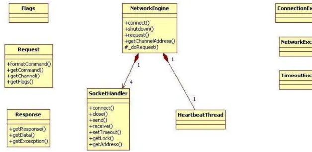
To deal with low level Ethernet sockets on the Soloist and low level socket API provided by Python, a networking layer was developed to be used by the Commander,
SoloControllerMonitor, and DualControllerMonitor classes. The network layer has the following structure.
Client code uses the NetworkEngine class to send requests to the Soloists and receive responses. The Request and Response classes are used to package data to be sent and received from the Soloists. When the client calls the request function, a request object is constructed and passed to _doRequest function which then communicates with either the ASCII Command Interface or WakeSurvey Feedback on the appropriate Soloist. The client specifies the request destination using a channel concept. There are four channels, two per Soloist. One channel is for the ASCII Command Interface the other for WakeServey Feedback. The channel actually represent different ports on the Soloist.
6
Channels are implemented as instances of the SocketHandler class. SocketHandler manages the Python socket that is connected to the Soloist. Python sockets operate at a lower level then sockets of other similar languages such as Java. One issue to deal with is that Python sockets deal with exceptions as either a general error or a timeout. The SocketHandler class uses these simple exceptions to produce more meaningful exceptions using the
ConnectionException, NetworkExecption and TimeoutExecption classes. Concurrent access control is provided by each SocketHander instance having its own lock.
Another issue is that the connection on the Soloist side timeouts after a period of time but the Python side doesn't become aware of this. One obvious solution is to open a new socket when sending and then closing this socket when the response is received. It was
determined through an earlier implementation that the Soloist's Ethernet system can't handle rapid open and closing of connections required by the application. Therefore the connection to the Soloist is left open. Most ASCII Command Interface commands return a response within a few milliseconds so the timeout on the Python socket is kept short to quickly detect failures. However the HOME command does not return a response until the home cycle is completed which can take several seconds depending on the travel distance and the home velocity. To deal with this issue a long running flag can be passed into the request to lengthen the timeout to prevent false errors. Additionally, a heartbeat thread is used to prevent timeouts due to application idle.
Logging System
Overview
The Logging System provides an abstraction layer for the underlying Python logging system. This places all of the logging configuration in a single location and also exposes any necessary logging support provided by the Python module without the need to directly import
7
elsewhere in the application. The Logging System configures three logger, a general purpose loggers, a logger for the controller system and a logger for the runfile execution system. These loggers operate on a rotating log file system. A system for connecting external components to the logging output is also provided. This is useful for GUI components.
Design
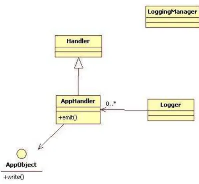
The design of the logging system is relatively simple due to the fact that it relies heavily on Python's logging module. This simplicity can be seen in the visual design shown below.
The LoggingManager is responsible for configuring the loggers, the file rotation and log record format. In addition to this the LoggingManager captures the three failure events from the controller (Communication Failure, Command Failure and Axis Fault) and logs them automatically. The client codes does not need to access the LoggingManger to get a reference
8
to a logger because the Python logging function getLogger is exposed through the module. For the most part the logging system module can be used like the Python logging module without the need to import.
The other major feature provided is the AppHandler class. This class extends the Python logging class Handler which allows direct interfacing with the Loggers. Classes that implement the AppObject interface can then be passed into a AppHandler instance and then registered with the loggers. When a log record is generated the logger calls emit on the AppHandler which then calls write on the AppObject passing in the string form of the formatted log record. One use case is connecting a GUI object to the logging system.
Configuration System
Overview
The configuration system allows persistence of the various settings needed by the application. These settings include the network address of the controllers. The format for storing the configuration files was XML. This was done due to the standardization and human readability of XML. Instead of manually constructing the XML from a Python class, the
configuration system allows the serialization of Python classes to XML. This allows quick development of additional configuration files.
To develop a configuration file first a Python classes is created which contains attributes with associated setters and getters. Decorators are then applied to the setters and getters. Once this is done the configuration system can now serialize and deserialize the class.
9
Design
This module is again of simple design, as seen below, given the user friendly features it provides when dealing with the configuration file.
The clients use the ConfigManager to access various configuration files. Calls in the ConfigManager will initiate the serialization process. When the ConfigManager is constructed it will attempt to deserialize the configuration files, if they are not present default files are
constructed. The ConfigFile class represents a configuration file. This can be any Python class with the only condition that the class has a zero argument constructer and the appropriate setters and getter are decorated.
The main components of the system are the Persister, Config and Setter classes. The Config and Setter classes are the decorators. Config is applied to the getter function and Setter is applied to the setter function. These classes add metadata to the function by leveraging the fact that in Python functions of a class are objects themselves and can have attributes added at runtime. The metadata contains type of the function, either a setter or getter, plus additional information for formatting the attribute value for serialization to XML. This additional
information is specified during the decorating process. Presister uses this metadata to either
10
serialize or deserialize the configuration file. To serialize (write function) the Persister uses reflection on the request class looking for functions that have the metadata with a type "getter". It then calls that function to get the value and using the additional information in the metadata converts the value to a XML version to write to the file. To deserialize (read function) the XML is parsed into a data structure. The client passes in a blank instance of the
configuration file object which is inspected using reflection to find the functions with metadata of type "setter". Additional information is used to format the XML data to match the type the configuration class is expecting. The function is then called applying the data to object.
RunFile System
Overview
The runfile contains all the points to visit during the wake survey. Additional information such as velocity and acceleration are contained in the runfile (see Appendix A for sample
runfile). The runfile is stored in XML format like the configuration files, again because of standardization and human readability. The runfile system is responsible for generation, persistence and execution of the runfiles.
Each point in the runfile consist of a x and y pair. For polar point the x value represents the radius while the y value represents the angle. Also included is a lag time to determine how long the stage is kept at that point for data to be collected. An executed flag in the point indicates if the point has be executed.
A separate application has been developed for the construction and editing of the runfile. This application uses this system to work with the runfiles and support creation, editing and saving of runfiles with a extension runx.
11
Typically there are more points to execute then travel distance available in the tank, therefore the points are split into runs. The runfile system provides support for this
requirement.
Design
The RunFile module is fairly complex, second only to the controller backend. As shown below there are several major classes involved in the module.
The Runfile class is the primary container that stores the runfile data. It contains several Point objects which represents the points. The Point class contains all the data associated with a single point. There are several functions in the Runfile class that are used to construct,
12
serialize and deserialize the Runfile. These functions use the RunFileGenerator, RunFileReader and RunfileXmlGenerator classes to perform these actions.
The RunFileGenerator class is responsible for constructing a RunFile instance. The class accepts data from a GUI which may be in string format and coverts the data to the correct format for the runfile. It also generates a set of points based on a start/end angle, a delta angle, and a set of radii. The generated points will form circles around the zero point with a radius that fall in the set of radii provided. The RunFileReader deserialize the XML file to construct a RunFile instance. The RunfileXmlGenerator class serializes the RunFile instance to XML and stores it in a file location provided to it.
To handle the splitting of points a run concept is used. The points are broken in to groups called runs and are executed as a group. The Run class represents a single run and contains a reference to all the points in that run. The process of execution occurs in two stages: initialization and then execution. For initialization, the stage is moved to the location of the first point, once at the location the system waits for an execution request. For execution the stage is moved to the current point. Once in location that system pauses for the point lag time. During this pause data it collected. This process repeats for the next point until all points have been visited. Both stages of execution can be paused or halted. A pause waits until motion is complete then pauses the execution or initialization process. A halt sends an abort to the Soloists which stop motions regardless of location. A halted run should be reinitialized.
To perform these stages, two runner classes are used _Initializer and _Executor. These class are built to run within the ExecutorThread which is associated with the Run.
The Event System
Overview
The event system allows for model decoupling and model event listening. The system is separated from the model and can be used as a communication medium for intermodal and
13
external communications. The event system is used heavily to broadcast Soloist status and fault changes including position and velocity changes.
Design
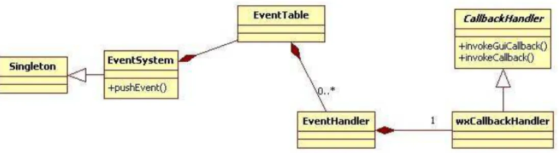
The event system is a fairly simple design which focuses on a single root class. The only real complexity is dealing with threading issues. Shown below is the main class structure of the event system.
One of the design issue that the event system has to deal with is thread safety with the GUI. Most GUI toolkits are not thread safe so components must only be updated on the main GUI thread. The event system needs to be able to call the event handler using the correct method depending on if the handler is a GUI component or not. The CallbackHandler class performs this task. If the event handler is a GUI component the call is injected onto the main GUI thread. The current implementation uses wxPython and uses the CallAfter function to inject the handler call on the main thread.
The EventHandler class contains the handler function pointer plus flags to indicate if this is a GUI based handler and if the callback is event source dependent. EventHandlers are stored in the EventTable class associated with a event type. The EventSystem class is the main class and follows the singleton pattern. Clients use this class to register handler and push events.
14
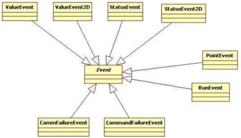
The event classes themselves have the follow structure:
All event classes extend a common base Event class. They are also generic in terms of which event type sends them. For example a ValueEvent instance is sent for position, velocity, position error, and velocity error events.
Soloist Based Programs
Wake Survey Feedback
The Wake Survey Feedback is a TCP/IP server that runs in Task 1 on the Soloist. Clients can send commands to obtain various status information on the controller. The rational for developing this server was to remove status polling from the ASCII Command Interface. Earlier version of the positioning software had issues with coordinating the rapid status polling and motion operations occurring through the ASCII Command Interface. A first attempt at this program was to have the client part on the Soloist and the server in the Controller Backend. However, it proved difficult to get the Soloist to connect to PC as a client so the server was developed on the Soloist. The server protocol is a follows:
15
Request: <Command><EOS>
Response: <Response Char>[<Data>]<EOS>
Note: Data not present in event of error
Command Usage
POS Get axis position
PERR Get axis position error
VFBK Get axis velocity
VERR Get axis velocity error
AXISSTATUS Get the axis status value
AXISFAULT Get the axis fault value
Table 1: Supported Commands
Response Meaning
% Command success data will be included
! Command failure data will not be included
Table 2: Response Characters
Control Character Meaning
\n End of Stream (EOS)
16
Analog Positioning
The Analog Positioning program runs in Task 3 on the Soloist. Its purpose is to output current position to the analog out on the Soloist. This allows the data acquisition system to sample this output for position recording, thus providing a replacement to the string potentiometer on the stage.
There are several issues that this software needs to handle for correct functionality. The first is the limitation of the digital to analog converter (DAC) on the Soloist. It is a 16 bit DAC with a recommended ±10V range, although the value is configurable through the Soloist configuration file. The issue is that position can take values beyond this range and the command AOUT which is used for output expects a voltage value. To solve this problem the position from the PFBK command is scaled to convert it to the equivalent value that falls in the ±10V range. This scalar is generated by taking the maximum travel distance of the axis (dmax)
and applying the following formula:
Equation 1: Analog Positioning Scalar Equation
The maximum travel distance is defined in the Soloist configuration file as UserDouble1 and therefore can be adjusted to match the stage dimensions. Once the scalar is setup the program enters a loop where position is read, scalar is applied, and resulting value is outputted. Controlling this loop is the second issue to deal with. There are two options: have it run
unbounded, regulated only by the Soloist task scheduler, or bound the loop using the sleep command (DWELL). The first option was chosen because the Soloist is setup to provide equal execution time to both the Analog Position and the Wake Survey Feedback program so an unbounded loop would not dominate the CPU because the scheduler forces a fix 50% split in execution time allotment. This means the output is updated as fast as the scheduler will allow and the data acquisition is responsible for sampling the output.
17
The diagram below demonstrates the startup and operation cycles of the analog positioning software.
Graphical User Interface Interactions
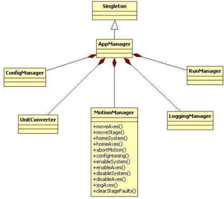
The GUI interacts with the backend through the AppManager system. A visual design of this system is shown below.
Figure 8: Analog Positioning Startup and Loop Sequence
18
The AppManager classes is the root of the backend and implements the singleton pattern. It allows access to the various backend managers plus a UnitConverter class which support unit conversions. Although, only a few conversions are supported and the current GUI still only operates using units of millimeters due to the Soloist being configured to operate in millimeters. The GUI can access the AppManager with relative ease due to the singleton implementation. However use of the singleton pattern was not for this reason but instead to prevent more than one backend from been created which would prevent communication with the Soloists.
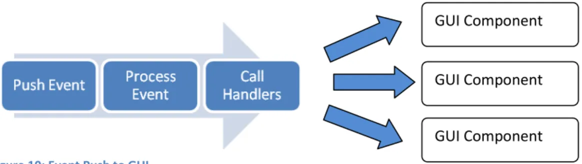
A second interaction pathway between backend and the GUI is through the event system. Backend end events can be sent to the GUI without any knowledge of each other which allows for effective decoupling between each other. In theory the event system could be used to signal the backend as well. In the current implementation this is not used or supported. The diagram below demonstrates how the event system interacts with the GUI.
Figure 10: Event Push to GUI
GUI Component
GUI Component
19
Conclusion
The various components of the Wake Survey Positioning Software are designed to perform the necessary tasks needed for the execution of a wake survey experiment. The design creates effective decoupling between the GUI and application backend. When combined with the two AeroBasic programs the Wake Survey Positioning Software can interface with and obtain status feedback from the Soloist Motion Controller.
Recommendations
Attempt modifications of the Wake Survey Feedback program so the client exists on the Soloist and the server in the Python application.
Continue to use XML as a file format.
Works Cited
20
A-1
Below is a sample runfile in XML format which the show the metadata and point XML structure
<runfile title="test" units="mm">
<diameter>212.0</diameter> <xvel>50</xvel> <xacc>50</xacc> <yvel>50</yvel> <yacc>50</yacc> <points numPoints="148">
<point axis="P" executed="False" xvalue="31.8" yvalue="0.0" />
<point axis="P" executed="False" xvalue="31.8" yvalue="10.0" />
<point axis="P" executed="False" xvalue="31.8" yvalue="20.0" />
<point axis="P" executed="False" xvalue="31.8" yvalue="30.0" />
<point axis="P" executed="False" xvalue="31.8" yvalue="40.0" />
<point axis="P" executed="False" xvalue="31.8" yvalue="50.0" />
<point axis="P" executed="False" xvalue="31.8" yvalue="60.0" />
<point axis="P" executed="False" xvalue="31.8" yvalue="70.0" />
<point axis="P" executed="False" xvalue="31.8" yvalue="80.0" />
</points>
</runfile>