REA
7?
~v1..MI~IY&
An Assessment of Internal
Blankets for Gas-Cooled
Fast Reactors
by
D. B. La ncaster and
M.
J.
Driscoll
Massachusetts Institute of Technology Department of Nuclear Engineering
Cambridge, Massachusetts
AN ASSESSMENT OF INTERNAL BLANKETS FOR GAS-COOLED FAST REACTORS
by D. Lancaster and M.J. Driscoll October 1980 MITNE-237
MITLiraries
Document Services
Ph: 617.253.2800 Email: [email protected] http://Iibraries.mit.edu/docsDISCLAIM ER
MISSING PAGE(S)
-3-ABSTRACT
An assessment of the use of internal blanket assemblies in GCFRs has been performed. This required the self-consistent optimization of a homogeneous design (a conventional core without internal blankets) and a heterogeneous design with internal blankets. The optimization was
followed by a detailed comparative analysis of representative versions
of the two types of cores.
The procedure started with the establishment of a set of parameters
characterizing a representative commercial-sized GCFR. Using constraints
on the peak clad temperature (7500C) and the peak linear heat generation rate (15 KW/ft), a thermal-hydraulic analysis was performed to yield acceptable fuel assembly designs for fuel pin diameters varying between
6 and 12 mm (corresponding to fuel volume fractions of 0. 236 to 0.487). Neutronic analysis of these assemblies in a homogeneous core arrangement
allowed comparison of their doubling time, energy growth potential and
fuel cycle costs. The 8 mm pin diameter (0.357 fuel volume fraction)
was selected as the optimum. The reasons for the doubling time depen-dence on pin diameter (or fuel volume fraction were explored and
explained in a generalized framework applicable to all FBR designs. The heterogeneous core optimization was performed by successively adding internal blanket assemblies to cores made up from the acceptable
fuel assembly designs. Since the fuel volume fraction of the internal blanket assemblies was as high as practicable (0.5), this procedure
allowed a steady progression to higher core-averaged effective fuel volume fractions. It was found that for small driver fuel pin diameters
the addition of internal blankets reduced the doubling time; whereas, for large fuel pin diameters the addition of internal blankets increased the doubling time. It was also found that for all fuel volume fractions the optimized homogeneous core had a shorter doubling time than the
hetero-geneous cores. Thus the optimum number of internal blanket assemblies was, in fact, zero. To continue the analysis, a heterogeneous core with 132 internal blanket assemblies, and 348 fuel assemblies, having a 7 mm fuel pin diameter, was selected as a reference design, since its core-averaged fuel volume fraction was the same as that of the optimum
homo-geneous core. Various blanket arrangements were studied and found to
have very little impact on doubling time.
Detailed analysis of the heterogeneous and homogeneous cores revealed that the former had: 1) a 5% longer doubling time, 2) a 10%
larger fissile inventory, 3) a 15% decrease in the core mixed-mean AT, 4) a 14% reduction in the fast fluence, 5) a 24% increase in the peak burn-up, 6) a 41% decrease in the power-density-weighted Doppler co-efficient,
7) a 15% increase in the fuel cycle cost, and 8) a 25% higher capital-cost-adjusted fuel cycle cost ($60 million higher capital costs attribu-ted to system changes required to accommodate the heterogeneous core). Overall, in view of these findings the homogeneous design is strongly
ACKNOWLEDGEMENTS
The work described in this report has been performed primarily by the principal author, D. Lancaster, who has
submitted substantially the same report in partial fulfill-ment of the requirefulfill-ments for the Ph.D. degree at MIT.
The funding for the present work was supplied by the General Atomic Company. Some of the work for this report was performed at their facility in San Dieqo. The authors wish to acknowledge the helpfulness and friendliness of all the persons contacted working on the GCFR project.
The authors wish to thank Ms. Annette Holman for her help, patience, and cheerfulness in the typing of the final manuscript.
-5-TABLE OF CONTENTS ABSTRACT 2 ACKNOWLEDGEMENTS 4 LIST OF FIGURES 9 LIST OF TABLES 13 CHAPTER 1. INTRODUCTION 17 1.1 Foreword 17 1.2 Background 19
1.3 Initial Investigations of Heterogeneous 23 Cores
1.4 Doubling Time 28
1.5 Review of Recent Developments 31
1.6 Outline of Present Work 32
CHAPTER 2. NEUTRONIC DATA BASE AND COMPUTER 37 CODES
2.1 Introduction 37
2.2 Cross Section Data Base and Treatment 38
2.2.1 LIB-IV 39
2.2.2 SPHINX Treatment 43
2.2.2.1 Resonance Self-Shielding 44 2.2.2.2 The Group Collapse 48
2.2.3 Fission Product Cross Sections 56
2.2.4 Summary Remarks on the Adequacy
of the Cross Section Treatment 59 2.3 Description of the Computer Codes Used 63
2.3.1 CALIOP 63
2.3.2 2DB 67
2.3.3 PERT-V 68
2.4 Summary 69
CHAPTER 3. HOMOGENEOUS CORE ANALYSIS 74
3.1 Introduction 74
3.2 Parameters Independent of the Homogeneous 75 Design Comparison
TABLE OF CONTENTS (contd.)
3.2.1 Basic GCFR Design Selection
3.2.2 Constrained Assembly Design
3.2.3 Blanket Assembly Design
3.3 Optimum Core Design Selection
3.3.1 Neutronics Methods for the
Optimization
3.3.2 Doubling Time Optimization
3.3.3 Energy Growth Potential
Optimization
3.3.4 Fuel Cycle Cost Optimization
3.3.5 Power Generation Cost Optimization
3.3.6 Homogeneous Core Optimization;
Summary
3.4 Fuel Management and Burnup Analysis
3.4.1 Fuel Loading and Shuffling Scheme 3.4.2 Analytical Techniques Used to
Arrive at the Equilibrium Cycle
3.5 Analysis of the Optimized Homogeneous Core Equilibrium Cycle
3.5.1 Mass Flows and Doubling Time
3.5.2 Power, Burnup, Flux, and
Fluence Distributions
3.5.3 6 and Delayed Neutron
Parameters
3.5.4 Control Rod Analysis
3.5.4.1 Control Rod Requirements 3.5.4.2 Doppler Coefficients and
Temperature Defects 3.5.4.3 Control Rod Worths 3.5.4.4 Summary of the Control
Rod Analysis
3.5.5 Material Worths
3.5.6 Summary of the Homogeneous Core
Analysis
3.6 Summary
CHAPTER 4. HETEROGENEOUS CORE ANALYSIS
4.1 Introduction
4.2 Heterogeneous Core Optimization 4.2.1 Determination of the Driver
Pin Diameter and the Number of Internal Blanket Assemblies
4.2.1.1 Technique for Determining the Optimum Effective Fuel Volume Fractions
76
77
83
85
86
90
107
111
117
118
122
123
126
130
130
135
145
147
147
150
154
157
157
165
165
167.
167
169
169
169
171
-7-TABLE OF CONTENTS (contd.)
4.2.1.2 Optimum Effective Fuel 184 Volume Fraction: Results
and Discussion
4.2.1.3 Summary of the Determina- 194 tion of the Driver Fuel
Pin Diameter and the Num-ber of Internal Blanket Assemblies
4.2.2 Investigation of the Effect of the 195
Heterogeneous Core Arrangement
4.2.3 Summary of the Selection of an 205
Optimum Heterogeneous Core
4.3 Fuel Management and Burnup Analysis 206 4.3.1 Fuel Loading and Shuffling Scheme 206
4.3.2 Analytical Techniques Used to 212 Arrive at the Equilibrium Cycle
4.4 Analysis of the Optimized Heterogeneous 214 Core Equilibrium Cycle
4.4.1 Mass Flows and Doubling Time 214 4.4.2 Power Analysis Distributions 223
4.4.3 Flux, Fluence, and Burnup Analysis 235
4.4.4 3 and Delayed Neutron Parameters 244
4.4.5 C8Arol Rod Analysis 244
4.4.5.1 Control Rod Requirements 246 4.4.5.2 Doppler Coefficients and 246
Temperature Defects
4.4.5.3 Control Rod Worths 252
4.4.6 Material Worths 254
4.4.7 Summary of the Equilibrium
Hetero-geneous Core Analysis 257
4.5 Summary 259
CHAPTER 5. ECONOMIC ANALYSIS 260
5.1 Introduction 260
5.2 Fuel Cycle Costs 261
5.2.1 Fuel Cycle Cost Model 261
5.2.2 Fuel Cycle Costs for the 264
Heterogeneous and Homogeneous Designs Using Nominal Cost Assumptions
5.2.3 Sensitivity to Plutonium Value 269
5.2.4 Sensitivity to Fabrication Costs 271
5.2.5 Sensitivity to Reprocessing Costs 275
5.2.6 Sensitivity to the Time Value of
Money 275
TABLE OF CONTENTS (contd.)
5.3
Capital Cost Differences
279
5.4 Summary 280
CHAPTER 6.
SUMMARY,
CONCLUSIONS,
AND R.ECOMMENDATIONS
282
6.1
Introduction and Background
282
6.2 Overview of Procedure
283
6.3
Salient Observations
288
6.3.1
Doubling Time Dependence on Fuel Volume
289
Fraction
6.3.2 Method for Heterogeneous Core Optimization
292
6.3.3
Qualitative Explanation for Doubling Time
294
Differences
6.4
Conclusions
297
6.4.1
Real Heterogeneous Effects
297
6.4.2
Recommendations for the GCFR
301
6.4.3 Comments Relevant to the LMFBR
302
6.5
Recommendations for Future Work
303
APPENDIX A. Changes to 2DB
306
A.l 30* Symmetry Changes 307
A.2
Search-Burn Capability and Added Edits
312
A.3
Temporary Changes for Shuffling
318
A.4
Summary
320
APPENDIX B. Changes in PERT-V
321
B.l
Buckling and Current Edit
321
B.2
Zone-wise Reactivity Edit
329
B.3 Changes in MAIN and INP
330
B.4
Summary
335
-9-LIST OF FIGURES
Fig. No.
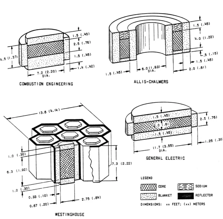
1.1 Reactor Core Arrangements in the Four 1000 MWe 20 Design Studies of 1964
1.2 The Parfait Blanket Concept 22
1.3 Comparison of CRBR Core Configurations 27
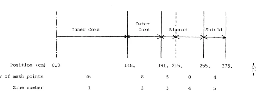
2.1 One-Dimensional Radial Model of a GCFR 51
Used for SPHINX Group-Condensation
2.2 Calculational Path Employed in the Present Work 73 3.1 Basic GCFR Upflow Core Configuration 79
3.2 Homogeneous Core Layout 87
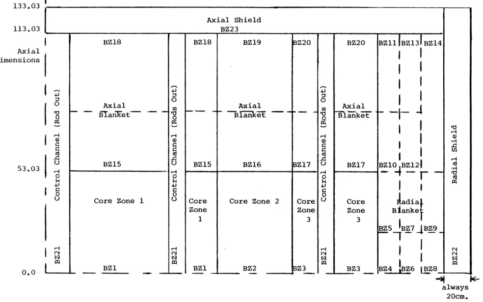
3.3 R-Z Model Used for the Homogeneous Core 88
Analyses
3.4 Doubling Time as a Function of Fuel 95
Pin Diameter
3.5 Doubling Time as a Function of Fuel Volume 96
Fraction
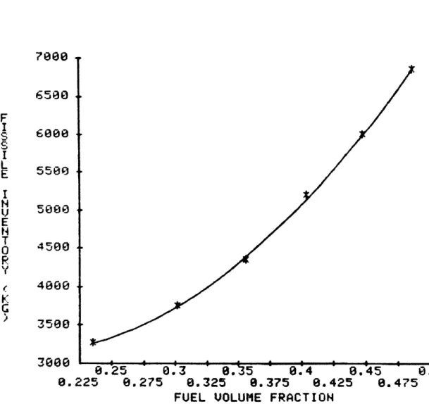
3.6 Fissile Inventory as a Function of 98
Fuel Volume Fraction
3.7 Net Fissile Gain as a Function of Fuel 99
Volume Fraction
3.8 Breeding Ratio as a Function of Fuel 100 Volume Fraction
3.9 Doubling Time as a Function of Fuel 103
Volume Fraction Under Various Constraints
3.10 Power Potential Index as a Function of 110
Fuel Pin Diameter at Various Years After GCFR Introduction
3.11 Fuel Cycle Cost as a Function of Fuel 114
Pin Diameter
3.12 Fuel Cycle Costs Adjusted for Capital 120
Cost Differences as a Function of Fuel Pin Diameter
LIST OF FIGURES (contd.)
Fig. No.
3.13 Fuel Loading Pattern for the Reference 124
Homogeneous Core
3.14 The Ratios of the Local Power Density to 138
the Active Core Height Averaged Power Density as a Function of the Vertical Distance from the Core Midplane
3.15 The Ratio of the Local Power Density to 139
the Active Core Height Averaged Power
Density for Each of the Radial Blanket Rows
3.16 Peak Kw/ft at BOEC for the Reference 140
Homogeneous Core
3.17 Peak Kw/ft at EOEC for the Reference 141
Homogeneous Core
3.18 BOEC Peak Flux for the Reference 143
Homogeneous Core
3.19 EOEC Peak Flux for the Reference 144
Homogeneous Core
3.20 Homogenous Core Neutron Energy Spectrum 146
3.21 Doppler Coefficient at the Core Midplane 152
for the Reference Homogeneous Core
3.22 Axial Traverse of the Doppler Coefficient 153
for the Reference Homogeneous Core
3.23 Adjoint Spectrum for the Homogeneous Core 160
3.24 Axial Traverse of the HT-9 Reactivity 162
Worth for the Reference Homogeneous Core
3.25 Fuel Worth as a Function of Radial Position 163
for the Reference Homogeneous Core
3.26 Fuel Reactivity Worth as a Function of 164
Axial Position for the Reference Homogeneous Core
4.1 Heterogeneous Core I with 18 Internal 172
Blanket Assemblies and 378 Fuel Assemblies
4.2 Heterogeneous Core II with 36 Internal 173
-11-LIST OF FIGURES (contd.) Fig. No.
4.3 Heterogeneous Core III with 54 Internal 174 Blanket Assemblies and 366 Fuel Assemblies
4.4 Heterogeneous Core IV with 96 Internal 175
Blanket Assemblies and 354 Fuel Assemblies
4.5 Heterogeneous Core V with 132 Internal. 176
Blanket Assemblies and 348 Fuel Assemblies
4.6 Heterogeneous Core VI with 204 Internal 177
Blanket Assemblies and 342 Fuel Assemblies
4.7 R-Z Model for Heterogeneous Core I 178
4.8 R-Z Model for Heterogeneous Core II 179
4.9 R-Z Model for Heterogeneous Core III 180
4.10 R-Z Model for Heterogeneous Core IV 181
4.11 R-Z Model for Heterogeneous Core V 182
4.12 R-Z Model for Heterogeneous Core VI 183
4.13 Doubling Time as a Function of the Effective 189
Fuel Volume Fraction for Various Homogeneous and Heterogeneous Designs
4.14 Fissile Inventory as a Function of Effective 193
Fuel Volume Fraction
4.15 Heterogeneous Core Arrangement VA 196
4.16 Heterogeneous Core Arrangement VB 197
4.17 Heterogeneous Core Arrangement VC 198
4.18 Heterogeneous Core Arrangement VD 199
4.19 Heterogeneous Core Arrangement VE 200 4.20 Heterogeneous Core Arrangement VF 201 4.21 Fuel Loading Pattern for the Reference 209
Heterogeneous Core
4.22 Normalized Axial Power Shape for the 225
Driver Assemblies of the Reference Heterogeneous Core
LIST OF FIGURES (_contd.) Fig. No.
4.23 Normalized Axial Power Shapes for the 227
Burned and Fresh Internal Blankets for the Reference Heterogeneous Core
4.24 Peak Kw/ft for Assemblies at BOEC for the 228
Reference Heterogeneous Core
4.25 Peak Kw/ft for Assemblies at EOEC for the 229
Reference Heterogeneous Core
4.26 Peak Flux for BOEC for the Reference 236
Heterogeneous Core
4.27 Peak Flux for EOEC for the Reference 237
Heterogeneous Core
4.28 Neutron Energy Spectrum in the Driver Fuel 239
Regions of the Reference Heterogeneous Core
4.29 Neutron Energy Spectrum in an Internal 240 Blanket Assembly of the Reference
Heterogeneous Core
5.1 Sensitivity of Fuel Cycle Costs to the Value 270
of Plutonium
5.2 Sensitivity of the Fuel Cycle Cost to the 272
Driver Fuel Fabrication Cost
5.3 Sensitivity of the Fuel Cycle Cost to the 274 Blanket Fabrication Cost
5.4 Sensitivity of the Fuel Cycle Cost to the 276
Reprocessing Cost
5.5 Sensitivity of the Fuel Cycle Cost to the 278 Discount Rate
6.1 Flow Chart for the Comparison of Hetero- 285
geneous and Homogeneous Cores
6.2 Doubling Time as a Function of Fuel Volume 290
Fraction under Various Constraints
6.3 Doubling Time as a Function of the Effective 295
Fuel Volume Fraction for Various Homogeneous and Heterogeneous Designs
-13-LIST OF TABLES
Table No.
1.1 A Representative Comparison of Parfait 24
Blanket and Conventional LMFBR's
1.2 A Comparison of Homogeneous and 26
Heterogeneous CRBR Cores
1.3 Summary of Homogeneous Versus Heterogeneous 33 Core Comparisons
2.1 Neutron Energy Group Boundaries for Ten 49 Group Design Level Cross Section Sets
2.2 Collapsing Spectrum Employed as a Function 52
of Assembly Type
2.3 Errors Introduced by Group Condensation 55
2.4 Energy Boundaries for the Japanese Fission 57
Products and for LIB-IV Cross Sections
2.5 Comparison of Intra-Laboratory Integral 61
Parameter Results
2.6 Neutron Spectrum Comparison from CSEWG 62
Problem 1: ZPR-6-7 Infinite Homogeneous Medium Flux
2.7 Reactor Design Areas Supported by 71
Critical Experiments for CRBR
2.8 ZPPR Criticality Predicted by CRBRP 71
Design Methods
2.9 ZPPR Reaction Rate Summary 72
2.10 ZPPR Control Rod Worth Calculation-To- 72 Experiment Ratios
3.1 Key Characteristics of the GCFR Used in 78
the Present Work
3.2 Compatible Fuel Assembly Designs for 82
Various Fuel Pin Diameters
3.3 Control and Shield Compositions 89
3.4 Results of the Analysis of Homogeneous Cores 94 Using Acceptable Thermal-Hydraulic Assembly
LIST OF TABLES (contd.)
Table No.
3.5 Analysis of Homogenous Cores Without 102 Thermal-Hydraulic Constraints
3.6 Analysis of Homogeneous Cores Without 105
Thermal-Hydraulic Constraints and
Critical Only at the Beginning-of-Cycle
3.7 Fuel Cycle Costs for Various Homogeneous 113
Core Designs
3.8 Results of Analysis Using A Constant Burnup 116 Assumption
3.9 Power Generation Cost Optimization 119
3.10 Homogeneous Core Optimization Summary 121
3.11 Eigenvalues at the Start and End of the 127
First Six Cycles for Fixed Assembly Feed Compositions
3.12 Mass Flows for the Homogeneous Core 131
3.13 Homogeneous Core Doubling Time 134
3.14 B and Delayed Neutron Parameters for 148 t~e Reference Homogeneous Core
3.15 Homogeneous Doppler Coefficients 151
3.16 Temperature Defect and Control Requirements 155
for the Reference Homogeneous Core
3.17 Control Rod Worths and Requirements for the 156
Reference Homogeneous Core
3.18 Material Worths for the Reference Homogeneous 158
Core
4.1 Key Results of Heterogeneous Core Analysis 185 4.2 Comparison of Cores with the Same Effective 190
Fuel Volume Fraction but Different Numbers of Internal Blanket Assemblies
4.3 Performance of Heterogeneous Core Arrangements 203 Having the Same Driver Fuel Pin Diameter and
-15-LIST OF TABLES (contd.)
Table No.
4.4 Heterogeneous Core Feed Enrichments and End 211 of Cycle k eff for the First Six Cycles
4.5 Mass Flows for the Heterogeneous Core 215 4.6 Comparison of Parameters Determining the 218
Doubling Time of the Reference Equilibrium Homogeneous and Heterogeneous Cores
4.7 Detailed Neutron Balance for BOEC Reference 220 Heterogeneous and Homogeneous Designs
4.8 e and Delayed Neutron Parameters for the 245 Re erence Heterogeneous Core
4.9 Heterogeneous Core Doppler Coefficients 247 4.10 Temperature Defect and Control Requirements 249
for the Reference Heterogeneous Core
4.11 Time Constants for the Heterogeneous and 250
Homogeneous Fuel and Blanket Pins
4.12 Control Rod Worths and Requirements for 253
the Reference Heterogeneous Core
4.13 Material Worths for the Reference Hetero- 255
geneous Core
5.1 Fuel Cycle Costs for the Reference 265
Homogeneous Core
5.2 Fuel Cycle Costs for the Reference 267
Heterogeneous Core
6.1 Some Important Characteristics of the GCFR 286
Adopted as "Given Conditions" for the Present Work
6.2 Summary Comparison of the Reference Homogen- 299
eous and Heterogeneous Cores
LIST OF TABLES (contd.)
Table No.
A.2 Changes in INP for Improved Storage 314
A.3 The SHUF Subroutine Allowing Shuffling 319
of Number Densities Between Cross Section Sets
B.l The SLOPE Subroutine Modified to Provide 323
a Zone-wise Flux, Current, and Axial Buckling Edit
B.2 Sample Output of the Zone-wise Reactivity 328
Worth Calculation
B.3 Sample Output From the Edit of Zone-wise 331
Fluxes, Currents, and Axial Bucklings
B.4 The CALZ Subroutine to Calculate Zone-wise 332
Reactivity Worths
B.5 The MAIN Subroutine Modified for the PERT-V 334 Improvements
-17-CHAPTER 1
INTRODUCTION
1.1 Foreword
Over the past several years the use of internal blankets (in so-called heterogeneous core designs) has attracted
considerable attention among liquid metal cooled fast breeder reactor (LMFBR) designers. However, except for an examination of its alternative fuel cycle potential by ORNL as part of the NASAP/INFCE programs (Wl), little has been done to assess the utility of heterogeneous designs for the gas-cooled fast reactor (GCFR). Thus the objective of the present work,
undertaken under contract to the General Atomic Company, is to evaluate whether a heterogeneous core is advantageous for a GCFR.
The term "heterogeneous" in the present context refers to the use of depleted uranium assemblies inside the fissile
fueled core zones. Due to the low power density of these assemblies they can be constructed of larger diameter fuel pins and with a higher fuel volume fraction than the fissile
fueled assemblies. The internal blanket assemblies are very similar to radial blanket assemblies,but since the internal blankets run at a higher power density than the radial
blankets the pin diameters of the internal blankets in this work have been made slightly smaller (127 pins per internal
blanket assembly versus 91 pins per radial blanket assembly
and 271 pins per fissile fueled assembly).
It is now generally accepted that the primary incentive
for the introduction of heterogeneity into LMFBR designs is
the resulting decrease in sodium void worths. Clearly this is
not a valid motivation in the case of the GCFR. At the outset
of the present study a number of alternative improvements
conferred by the use of internal blankets were postulated for
the GCFR:
better breeding, reduction of fluence, less
reactivity swing per cycle, and the like. All of these
hypotheses will be explored,but the main focus of this work
will be to find the design which will yield the lowest power
generation cost. Design and safety implications will be
evaluated, but in general they will not intervene as limiting
criteria. Since the LMFBR and the GCFR are similar in a
number of ways this work will also have implications regarding
the value of changing an LMFBR to a heterogeneous core design
when the total cost rather than the sodium void worth is the
figure of merit.
Thus, although this work centers on GCFRs,
comments on the applicability to LMFBRs will be included
wherever appropriate.
This work concentrates on the uranium/plutonium fuel
cycle, since it permits by far the best neutronic and
economic performance. The use of thorium internal blankets
has been investigated by White and Burns (Wl),who found no
advantages of note over the conventional uranium/plutonium
-19-fuel cycle, but instead found the normal degradation in core neutronic performance associated with substituting thorium for uranium in a fast reactor. Further investigation would
require incentives not now in evidence. Hence the thorium fuel cycle has been left for further work.
1.2 Background
For all practical purposes breeder reactors provide access to an inexhaustible energy supply, with all of the desirable implications that this capability conveys. This considerable incentive to develop breeders was recognized in the mid-1940's
by Enrico Fermi and his associates (Fl). Since that time
there has been continuous work to conceptualize and implement improvements in breeder designs. The first breeder was an LMFBR, EBR-I; it went critical in August 1951. It was also the first nuclear power plant of any type to produce electri-city, a goal achieved on December 20, 1951. EBR-II and the Fermi Fast Breeder Reactor followed over the next two decades. It is interesting to note that the early design of EBR-II had seven internal blanket assemblies for power flattening (Bl) which, however, were removed from design plans by 1958.
In the early 1960's plans were being made for large commercial LMFBR's. By this time it was known that coherent large-volume sodium voiding could cause a large reactivity
insertion. Thus all four design concepts developed for the
.76)
(.142)
COMBUSTION ENGINEERING ALLIS-CHALMERS
.25 (.38) GENERAL ELECTRIC (2.22) LEGEND CORE BLANKET SODI UM REFLECTOR
o.87 (.20) '" DIMENSIONS: xx FEET; (xx) METERS
WEST INGHOUSE
Fig. 1.1 REACTOR CORE ARRANGEMENTS IN THE FOUR 1000 MWe DESIGN STUDIES -OF 1964
(Tl)
-21-the four designs envisioned at that time. Two of -21-these designs had what today would be called internal blankets. The core with the best predicted economic performance was the carbide core evaluated by Combustion Engineering, which did not employ internal blankets. It should be pointed out, however, that the dominant design constraint on all these cores was sodium voiding, with the econonics playing a distinctly secondary
role. It was during this same period (from 1961 on) that GCFRs were being first developed. Since there was no sodium void problem with a GCFR no "spoiled" geometries were investigated
(helium loss through depressurization is accompanied by a comparatively small reactivity addition). Gradually through the sixties the "spoiled" geometry design lost favor to the simpler cylindrical "homogeneous" designs, since it was concluded that coherent large-scale sodium voiding required
"a major accident of an incredible nature" (Hl). However,
even as late as 1969 Westinghouse was still proposing a modular core, although pointing out its economic disadvantages (T2).
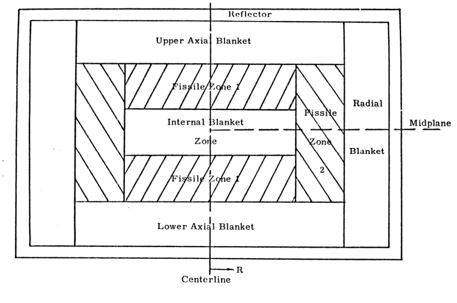
From 1970 to 1975 it was generally agreed that the preferred design of a fast reactor, whether GCFRs or LMFBRs, would be to incorporate a cylindrical homogeneous core. One exception to this mainstream effort is reflected in work by Ducat, who evaluated the "parfait blanket" concept for fast breeder reactors (Dl). In this approach depleted uranium was placed in the center of each fuel assembly, as shown in Fig. 1.2. Many of the advantages and disadvantages put forth
Centerline
wowc
R
-23-by Ducat for the parfait concept, as summarized in Table 1.1,
are also associated with the heterogeneous core concept.
At this point some nomenclature should be clarified. In this work the term "heterogeneous" is used to refer to any core containing full length radial-blanket-like assemblies of
depleted uranium in the active core region. Because of many common features between this and the "parfait" cores described
by Ducat the term "parfait" has been widely used by many
working in this area to describe any core with internal
blankets,be they full length assemblies of depleted uranium or axial sections of depleted uranium in a fuel assembly. In this work the term "parfait" will be left for the Ducat type core only. Another potential point of confusion is with the term "internal blanket." Clearly the parfait cores have segments that could be referred to as internal blankets, but in this work the term is reserved for full length radial-blanket-like assemblies of depleted uranium.
1.3 Initial Investigations of Heterogeneous Cores
Most of the controversy over the true nature of hetero-geneous core performance starts with the paper presented by Mougniot at the European Nuclear Conference in April, 1975
(Ml). In this paper it is claimed that the heterogenous core shortens the doubling time (from 22 to 11 years for the
example used), decreases the reactivity swing over a cycle, lowers the fast fluence, and decreases the sodium void worth.
Table 1.1
A Representative Comparison of Parfait Blanket and
Conventional LMFBRs (Dl)
Advantages
Increased breeding ratio (2%) Decreased doubling time (10%) Decreased peak fast flux (25.5%)
Decreased wrapper tube elongation (29%) Decreased wrapper tube dilation (37.5%) Decreased burnup reactivity swing (25%)
Fewer control rods in core More fuel assemblies in core
Reduced losses of neutrons to control poisons Decreased peak power density (5%)
Decreased peak fuel burnup (7.6%) Decreased fuel swelling
Increased overpower operating margin
Flatter radial flux and power profiles in the inner core zone
Decreased thermal bowing
Decreased fluence-induced bowing
More favorable sodium void characteristics Potential for higher core fuel volume fraction
Disadvantages
Increased core fissile inventory (3.9%) Reduced power Doppler coefficient (8%) Higher peak clad temperature (17*F)
-25-The paper was reviewed in some detail by Chang (Cl) at
Argonne National Laboratory (ANL), who identified a number of inconsistencies. First, the peak linear heat generation rates were not the same in the heterogeneous and homogeneous cores
compared. Second, the external blankets of the heterogeneous core were much thicker. Third, the homogeneous core was at an off-optimum fuel volume fraction. Chang concluded that the doubling time cannot be improved by utilizing the heterogeneous concept. Although Chang shows that most of the doubling time advantage claimed by Mougniot is not due to heterogeneity, a fully convincing demonstration that heterogeneity cannot yield any advantage has not yet been presented.
In spite of the dispute over the reality of doubling time improvement, the heterogeneous concept was enlisted to improve the performance of theClinchRiver Breeder Reactor
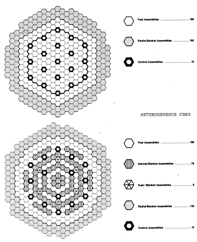
(CRBR). As demonstrated in Table 1.2 the CRBR shows great improvement with the use of internal blankets. Figure 1.3 shows the reference and an early heterogeneous design of the CRBR. The heterogeneous design, called the Alternate Fuel Management Scheme (AFMS), was reviewed by Chang, et al. (C2). They concluded that the doubling time improvement in the CRBR was due to the increase in the volume-averaged fuel volume fraction rather than the heterogeneity per se. Once again Chang concludes that comparably-optimized heterogeneous cores will always have slightly longer doubling times. In
Table 1.2
A Comparison of Homogeneous and Heterogeneous CRBR Cores (C2, C3, L4)
Homogeneous Heterogeneous
Breeding Ratio
Fissile Inventory (Kg) Doubling Time (yr)
Maximum Sodium Void
Worth
($)
Fast Fluence (n/cm2)1.08
1273
95.
$3.90 $4.00 BOC EOC %2.0 x 10231.21
1582
36.
$1.88
$3.90
1.4x10
2 3 Doppler Coefficient (BO%, - T dK/dT - 104) Fuel Total55.9
67.3
23.2 72.4
-27-HOMOGENEOUS CRBR
O
Fuel Asseelle ... 196 Radial Blanket Assem.es ... 150Control Assembies ... 19
HETEROGENEOUS CRBR
Q
Fuel Assembles ... 1s6 intemal Blanket Asseembies ... 76Fsel Blanket Assemblies ... 6
Radial Blanket Assembiles ... 132
0
Control Assemblies ... 15 Fig. 1.3 Comparison of CRBR Core Configurations (C3)were compared in a number of ways. However, the number of realistic homogeneous and heterogeneous designs examined
(two heterogeneous and three homogeneous) was too small to give confidence that further optimization of each core may not lead to different conclusions. Nevertheless, Chang et al., did
focus attention on the major reason for the improved performance of the heterogeneous CRBR, namely that the homogeneous CRBR
employed an off-optimum pin diameter. This is not surprising, since the pin diameter of the CRBR was constrained to be the same as that in the Fast Flux Test Facility (FFTF), since most of the data on mixed oxide fuel performance was at this pin diameter.
With the debate on heterogeneous cores well started, numerous papers were subsequently written comparing hetero-geneous to homohetero-geneous LMFBRs. Since the present work will cover much the same ground, but for the GCFR, a retrospective review of some of the earlier papers is in order. The para-meter of merit used in most studies of this genre has been doubling time. Thus, in order to prepare for the review of these earlier papers a discussion of doubling time follows.
1.4 Doubling Time
Doubling time, the time required to double the fissile material committed to a reactor, is an indicator of the growth and economic potential of a given reactor design. Energy
-29-supplies often use doubling time as their figure of merit. Energy economists likewise frequently use doubling time, since
it is a good measure of the return on investment. Doubling time can be written as:
Fissile Inventory
Doubling Time = (1.1)
Annual Fissile Return
Since the fissile investment is the largest monetary investment in the fuel cycle, the reciprocal of the doubling time is a good estimate of the rate of return on the investment.
Doubling time alone is not enough to calculate the actual fuel cycle costs or even the true energy potential in any year but it is commonly used as a figure of merit since it can be
determined directly from the core physics analysis with very few added assumptions. A more complete discussion of figures of merit will follow in Section 3.3 of Chapter Three.
The doubling time is often expressed in terms of various other familiar parameters to aid in understanding its
optimization. One such representation uses the breeding ratio (BR), the fissile capture-to-fission ratio (a), the total core thermal power (P), the ratio of fertile
fission-to-fissile-fis-sion (6), and the fissile inventory (FI). The breeding ratio measures the production of fissile material per absorption in
fissile material. (BR-l), then, is the net gain of fissile material per absorption. Multiplying this by (l+a)/(l+6), the ratio of fissile absorption to total fissions, yields the
production of fissile material per fission. The power (P) is related to the mass fissioned per unit time, and can therefore be used to convert the production of fissile material per
fission to a rate of production of fissile material. Using these factors and the fissile inventory which is to be doubled the following equation can be written for the doubling time:
DT = (2.6 MW.yr/Kg) FI (1+6)
(BR-1) (1+a)P (1.2)
where
DT is the doubling time in years
FI is the kilograms of fissile material tied up by the reactor (in and out of core)
BR is the breeding ratio
a is the fissile capture to fission ratio
6 is the ratio of fertile to fissile fissions
and P is the thermal power in MW.
This simple equation can be further elaborated upon, as was done by Aldrich (A3), but for this discussion this
elemen-tary version is all that is needed. The detailed doubling time definition for the present work is presented in
Sub-section 3.3.2 of Chapter 3.
From this equation it is clear that the doubling time can be made shorter by decreasing the fissile inventory or by
increasing the breeding ratio or power. The fissile inventory can be decreased by shortening the cycle length (requiring
-31-thereby less excess reactivitiy) by decreasing the core leakage,
by decreasing the non-fissile absorption, or by increasing the
fission cross section (by changing the neutron spectrum). The breeding ratio can be increased by decreasing reactor leakage, decreasing parasitic absorption, hardening the spectrum, or increasing the fertile capture cross section. The peak thermal power of a reactor design is generally as high as materials limits permit. In order to increase the thermal power the average conditions should be brought closer to the peak conditions, i.e.: improve the power flattening.
Unfortunately some of these objectives conflict with others: for example, decreasing fissile inventory by
decreas-ing non-fissile absorption is in direct conflict with increasdecreas-ing the breeding ratio by increasing the fertile capture cross
section. The present work will concentrate only on those effects on doubling time brought about by heterogeneity. We will strive to compare equally optimized homogeneous and heterogeneous designs: comparable optimization with respect to fuel volume fraction, fuel management, power flattening, and thermal hydraulic design is a foremost objective.
1.5 Review of Recent Developments
Shortly after the initial papers already discussed, the majority of the LMFBR community agreed that heterogeneous cores were desirable primarily because they decreased the sodium
void worth and thereby were expected to have less-energetic accidents. The argument as to whether or not they could also
improve economics was not pursued with any intensity since the
sodium void worth became the preferred figure of merit. Papers
have appeared upon occasion which compared heterogeneous to
homogeneous cores, but no major effort to resolve the
differ-ences among the various design communities has been made.
Since the GCFR design does not depend on sodium (or even
helium) void worth the question of whether it would benefit
from a heterogeneous core was left unresolved. Table 1.3
compiles most of the more prominent comparisons made to date.
A number of the publications are short, making resolution of the
differences difficult. Whenever possible,
comments are included
in the table to help identify obvious inconsistencies in the
comparisons.
1.6
Outline of the Present Work
The underlying objective of the present work is to
provide a sufficient basis for deciding whether or not a GCFR
should have a heterogeneous core design.
In view of the
reser-vations with respect to the adequacy of the comparisons just
outlined, this analysis contains an optimization study of both
the homogeneous and heterogeneous cores.
Because system
economics is to be preferred as the controlling figure of merit,
the study not only includes comparisons of fuel cycle costs,
but also differential capital costs that would accompany
either option. Finally, this study necessarily involves
numerous assumptions, so that the uncertainty in the final
results due to these assumptions is also addressed.
Table 1.3
Summary of Homogeneous Versus Heterogeneous Core Comparisons
Doubling Time (yrs)
Date Lab Homogeneous Heterogeneous Reference Comments
4/75 CEA/CEN- 22 11 Ml Fuel volume fraction and thermal-hydraulics
Cadarache not equally optimized. (KW/ft not constant
and the homogeneous core pin diameter too small.)
late WARD 95 36 Later pub- Fuel volume fraction not equally optimized
'75 lished as (homogeneous core pin diameter too small)
C3
4/19 ANL 21.6 23.0 C2 Not equally optimized fuel management. (The
homogeneous core had a shorter cycle.) In
general, however, this work was a good comparative study.
10/5/76 EPRI 16.9 18.2 Sl Modular core, no optimization
2/8/77 ANL 16,9 20.7 B2 Heterogeneous core is off the optimum fuel
volume fraction since internal blankets are added to an optimized homogeneous core.
6/77 WARD 19.5 16. P1 PLBR design
6/13/77 CEA 24 16. S2 Fuel volume fraction not equally optimized.
(A
Doubling Time (yrs)
Date Lab Homogeneous Heterogeneous Reference Comments
6/13/77 GE- 13 14 B3
Sunny-vale
7/5/77 ANL 20.7 22.7 T3
10/77 HEDL 11.6 19,0 C4
11/5/77 ANL 68.6 30.1 B4 Constrained to off optimum pin diameter for
the homogeneous core.
12/77 SNR 2 T 0.5T M2
Project
12/77 UK AEA 24 39 T4
12/77 CEA 29.5 12.8 El Off optimum fuel pin diameter in the homo
geneous core.
4/78 ANL 16.5 18.8 B5
4/78 GE- 22.2 16.7 Ll Constrained to an off optimum homogeneous
Sunnyvale fuel pin diameter.
4/20/78 ANL 13.7 17.2 01
6/78 AI 12.1 14.2 V2 Carbide fuel.
12/78 ORNL 12.7 10.2 Al
5/79 UK- 38. 28 B6 Constrained to an off optimum homogeneous
Risley fuel pin diameter.
6/79 ORNL 12.6 11.4 Wl Unoptimized GCFR: performed mainly as a
scoping study of alternate fuels.
-35-In the chapter just concluded the background necessary to define and understand the central problem posed has been established, and the previous applicable work has been pre-sented. In Chapter Two the physics data base is discussed along with the computer codes used in the analysis. The cross
section treatment is discussed and the assumptions and limita-tions are pointed out. Although no new computer codes of
any note were written for this work, modifications were made to existing codes and these modifications are introduced in the second chapter and discussed in detail in the appendices.
The third chapter is devoted to the analysis and optimiza-tion of the homogeneous core. It starts with a short review of GCFR plant parameters considered independent of the hetero-geneous versus homohetero-geneous core design decision, and contains a justification as to why some of these parameters were
selected. After that the optimum fuel pin diameter is selected and the reasons for the existence of an optimum are explained. With the pin diameter selected, the detailed analysis of the core is presented, along with a discussion of the methods used. The analysis includes fuel cycle mass flows; power, flux and fluence distributions; Doppler coefficients, control rod requirements and worths; and fuel, clad, and helium worths.
Chapter Four covers the selection and analysis of the heterogeneous core. The optimization of a heterogeneous core
is discussed and the results of this optimization is presented.
Again, as in Chapter Three, follow-on analyses provide all the relevant details needed for fuel cycle analysis and safety
The cost analysis is performed in Chapter Five. Using
data from Chapters Three and Four the fuel cycle costs are calculated, and associated capital cost differences are pre-sented. After all the costs have been analyzed the cost
differential between the heterogeneous and homogeneous cores is evaluated. The sensitivity of the cost differential to all the main economic data and cost assumptions is then calculated.
The last chapter, Chapter Six, summarizes the findings of the present work. It compares the costs, energy growth poten-tial, safety, and proliferation concerns associated with the heterogeneous and homogeneous cores. The implications of the work for the homogeneous versus heterogeneous decision are
-37-CHAPTER 2
NEUTRONIC DATA BASE AND COMPUTER CODES
2.1 Introduction
This work depends heavily on large computer code
calculations. In order to have confidence in such analyses the algorithms used in the codes and the data base supplied to the codes must be documented and validated. As in most
engineering problems many assumptions must be made to allow solution of the problem within reasonable time and cost
constraints. This chapter reviews the assumptions used in the cross section treatment and introduces the computer codes used in this work. The assumptions and approximations required in subsequent analyses are discussed as the need occurs in the later chapters.
The chapter begins with a discussion of LIB-IV, the cross section library used in this study. This is the
state-of-the-art library currently used by a number of fast reactor contractors, including Westinghouse. After the underlying assumptions used in the production of LIB-IV are pointed out, an explanation of the local cross section
treatment is presented. SPHINX, a code recently released by
Westinghouse, is used for this task (D2). The LIB-IV library as presently constituted does not have adequate fission
type of interest here, hence a discussion of this topic
follows the section on SPHINX. This completes the description
of the cross section treatment, which is concluded by a
com-parison with various other treatments.
Following the cross section exposition is a brief
abstract of each major computer code used in the remainder of
this work.
The codes are CALIOP, 2DB, and PERT-V. CALIOP is
an optimization code used by the General Atomic Company.
Since
there is as yet no published documentation on CALIOP it is
described in more detail than the other codes.
2DB, a two
dimensional diffusion theory burnup code, and PERT-V, a
per-turbation theory code, are well documented and are therefore
only briefly described in this chapter. However,
modifica-tions were made to both of these codes; hence the changes are
specifically noted. The coding for the changes is relegated to
the appendices.
This chapter is concluded with a summary of the
benchmarking of these methods against critical assembly data.
Although the benchmarking was done by other laboratories, it
adds considerable confidence to the validity of the techniques
used in this work.
2.2
Cross Section Data Base and Treatment
All of the cross sections used for this work come
from
the Evaluated Nuclear Data Files, ENDF/B-IV (G2).
They came
to MIT in two forms:
1) LIB-IV and 2) a Japanese Nuclear
-39-sections are treated with SPHINX, and then combined with the Japanese fission products to form the cross section sets used in the present work.
2.2.1 LIB-IV
LIB-IV is a well documented and tested library of
multigroup constants for reactor design (Kl). It is nationally available, and is in the form of Committee for Computer Code Coordination (CCCC) interface files (C5). It contains 49 fast energy groups and one thermal group, and therefore is mainly for use in fast reactor design. The library is in the
form of ISOTXS, BRKOXS, and DLAYXS files which are all
described in the CCCC reference (C5). There are data for 101 isotopes and, when the ENDF/B data permitted, the PO' P
1 1 2' and P3 Legendre components are included.
The library used in the present work was generated from the ENDF/B-IV data using the MINX program (W2). MINX takes the pointwise data and resonance parameters of ENDF/B-IV and applies an assumed flux shape to yield group constants. The flux shape assumed is:
C(E)
$(E,T,0 ) = a t(E,T) (2.1)
where
$ is the neutron flux,
E is the energy of the neutrons,
a 0is
the background cross section contributed
by other nuclides in the mixture,
a t
is the total cross section for the isotope under
consideration,
and
C(E) is the smoothly varying function chosen to describe
the overall flux shape.
Using this flux shape the cross sections are collapsed from
a continuous energy form to a group constant form using the
following equation:
f
a (E,T) $(E,T, a )dEa
(T,a
)
=g
X 0(2.2)x 0
f
$(E,T, a )dE
g
owhere the x subscript refers to an arbitrary reaction of type x,
and the g subscript refers to the energy group.
This technique should be recognized as the Bondarenko
self-shielding method (B7), where composition-independent cross
sections are generated as a function of a
0, the background
cross section. The LIB-IV ISOTXS file contains the infinitely
dilute cross sections, which correspond to a
= w.The LIB-IV
BRKOXS file contains the self-shielding factors ("F-factors")
for a set of temperature and a values which span the entire
range of designer interest. The F factors are defined as
the ratio of a cross section to its infinitely dilute value:
F (T, a ) = a (T,a )/ a (o,o) (2(3)
-41-These F factors and the infinitely dilute cross sections are used by SPHINX to generate composition dependent cross
sections as described in the next section.
If the cross sections are known as a function of energy,1 the major approximation used to generate LIB-IV is contained in the assumed slowly varying flux shape, C(E). The slowly varying flux shape, C(E), used for LIB-IV was a fission spectrum down to 820.8 KeV; from there down to 0.1 eV a 1/E weighting was used, and for the lowest energies a Maxwellian with a temperature of 0.025 eV was used. Using these shapes,
the equation for the flux (Eq. 2.1) is never rigorously correct; however, some familiar equations arise. At high energies the flux shape assumption takes the form:
$(E) = (2.4)
St(E)
where X (E) is the fission spectrum.
This formulation is valid, strictly speaking, if the down-scattering source of neutrons into dE about E is small
compared to the fission source. Since this approximation is used only above 820.8 KeV, this treatment represents a
reasonable simplification. For the rest of the energies important to a GCFR the flux shape assumption can be reduced to:
Determining the correct cross section shape as a function of energy is non-trivial, especially in the unresolved reson-ance region. For the MINX approach see reference (W2).
$(E) = 1 (2.5) E Zt(E)
This flux shape would be correct for a hydrogenous system with negligible absorption. It is also approximately the correct
shape for a mixture of heavy nuclides exhibiting weak absorp-tion (assuming Z(E) is almost energy independent over any
energy group). Unfortunately, since absorption is implicit in problems of present interest, this flux shape is imprecise; fortunately the resulting error is small for several reasons. First, this flux is used to collapse only to the fine group structure. Since there are fifty fine groups, the shape discrepancy over the narrow energy bands involved is small. Second, if the cross sections themselves do not change signifi-cantly as a function of energy,the shape of the flux used for intra-group weighting has no effect. Many of the important cross sections do not vary substantially in the energy band
bracketed by a fine group. Finally, although the slowly varying flux shape may not be correct, the flux shape at a resonance is controlled by the 1/Z t(E) factor, which is a good
approxima-tion if the loss in neutron energy in a scattering collision is large compared to the resonance width. In other words, Eq. 2.5 should be recognized as the narrow resonance approximation, which is a reasonable approximation for fast reactors.
Another assumption in the Bondarenko method is that the flux shape is smooth except for the dips caused by the
-43-resonances of the particular isotope under consideration. This is clearly not the case since resonances of Pu-239 and U-238 do overlap. This problem is hard to quantify, and as greater cross section accuracy is attained may force adoption of an improved method. Most of the overlapping resonances occur in the lower energy groups which are not important to a GCFR
with respect to its economic performance. However, most of the contribution to the Doppler-broadening reactivity occurs at these neutron energies.
Unfortunately, due to the cost of running problems in
50 energy groups, more approximations must be made to reduce
the data to composition-dependent 10 energy group cross sections. In order to do this the code SPHINX was used.
2.2.2 SPHINX Treatment
The SPHINX code is the mate to MINX in the CCCC plan for cross section treatment (D2). The code has two major sections. The first section generates the composition-dependent fine group cross section library by finding the correct F factors and then applying them. The second section uses a one dimensional diffusion calculation to deduce the fifty group flux by region. That flux is then used to collapse the cross sections to any specified broad group structure.
For this work the number of SPHINX treatments was limited to two analyses as part of the overall compromise involved in allocating resources to the various subtasks. From these
two runs, however, 162 individual collapsed cross section sets
were obtained. To describe these cross sections and the
approximations involved, the collapsing process and the reson-ance self-shielding will be discussed separately.
2.2.2.1 Resonance Self-Shielding
Nine different composition-temperature sets were used for the resonance self shielding. They were:
1) Inner Core, which has approximately a 12% fissile plutonium enrichment. The fuel was assumed to be at 1300*K. The clad and helium were assumed to be at
8000K. (Approximate hot full power temperatures.) 2) Inner Core again, but with 600*K and 5000K assumed
for the fuel and structure/helium temperatures respectively. (Approximate shutdown temperatures)
3) Outer Core, which has approximately an 18% fissile plutonium enrichment. Temperatures were assumed to be the same as the hot full power temperatures
assumed for the inner core.
4) Outer Core at the shutdown temperatures.
5) Radial Blanket of depleted uranium (no plutonium). The same hot full power temperatures were assumed.
6) Radial Blanket at shutdown temperatures.
7) Axial Blanket of depleted uranium (no plutonium).
The same hot full power temperatures were assumed.
8) Axial Blanket at shutdown temperatures, and
-45-The number densities for these mixes were obtained from the General Atomic submittal to the Nonproliferation
Alternative Systems Assessment Program (NASAP) (G-1), and do not correspond directly to any of the mixes used later in this work.
The actual treatment of these mixes is straightforward. Since the mixes are assumed homogeneous, a is found by adding up the macro total cross sections of all the isotopes other than the one being considered and dividing it by the number density of the isotope under consideration. In mathematical terms:
a 0 1 ' N a (2.6)
N i
i/j
where
i and
j
are superscripts identifying the isotopes involved,N is the number density (nuclei per barn cm), a t is the total microscopic cross section for
isotope i (barns),
and a is the background cross section for isotope
j.
Since at changes as the self shielding is imposed, the procedure requires iteration. For this work five iterations were performed. The iteration proceeds as follows. First the
a for an isotope in the mixture is calculated. Second, using this a and the temperature an interpolation among the a0
values and temperatures in the Bondarenko file (BRKOXS) is performed to find a particular F factor. (LIB-IV contains six different a s and three temperatures). Once the F factor is determined the infinitely dilute cross section is multiplied
by the F factor, and the resulting cross section replaces the
old value. Separate F factors are computed for the capture cross section, fission cross section, and elastic scattering cross section. The calculations are performed for every isotope in the mixture before starting the next iteration. Finally, this iteration is performed for each energy group.
A number of fairly important assumptions were made in
the resonance treatment. The first major assumption was that five sets of compositions were sufficient. This assumption is important, since in the five sets selected there is no low-enrichment plutonium set corresponding to the case at the end of life in an internal blanket. All of the plutonium iso-topes are assumed to be infinitely dilute in the blanket mixes. This omission is satisfactory since the spectrum averaged
one-group a for Pu-239 only decreases 1% if the full self shielding of a core mix is used. The second major assumption was that the core cross sections, which were based on a design that had a fuel volume fraction of 28.5%, would be valid for all of the various designs investigated. In order to evaluate
this concern, the spectrum averaged one group capture cross section for U-238 in the axial blanket (0.285 fuel volume fraction) was compared to the one group capture cross section
-47-for U-238 in the radial blanket (0.5 fuel volume fraction). Both were collapsed over the same spectrum. The difference was 2.3%, with the axial blanket cross section the lower of
the two, as expected. Since the fuel volume fractions
investigated in this work varied from 0.24 to 0.48, which is close to the range examined, and since the variation observed is tolerable, this simplification was also judged acceptable. Another assumption is the characterization of these five mixes as homogeneous and infinite. No pin description and
associated Dancoff factor was used since the actual geometry and pin sizes were not yet known and also since the assump-tion of homogeneity is a reasonably good one for fast reactors. The homogeneous approximation was investigated by ANL for
the second Large Core Code Evaluation Working Group benchmark. They found that it decreased keff by 0.2 to 0.3% in an LMFBR; a lesser impact would be expected in the harder spectrum of the GCFR. The committee concluded that "heterogeneity
effects are not sufficient to impact on scoping studies" (K3). The effect is small due to the fact that the mean free path of resonance energy neutrons is about 15 mm, which is
approximately twice the pin diameter.
The infinite medium assumption has been shown by
Saidi (S3) to be sound by both experiment and analysis. He showed that interfacial effects in fast breeder reactor
media are important only in the first three or so centimeters on either side of the interface. In the present work the